2019 MERCEDES-BENZ GLE COUPE oil pressure
[x] Cancel search: oil pressurePage 22 of 370
T
Tachometer ........................................ 208
Tailgate
Display message ............................ 248
Emergency unlocking ....................... 85
Important safety notes .................... 82
Limiting the opening angle ............... 85
Opening dimensions ...................... 364
Opening/closing (automatically
from inside) ...................................... 84
Opening/closing (automatically
from outside) ................................... 83
Opening/closing (from outside) ....... 82
Tank content
Fuel gauge ....................................... 36
Technical data
Capacities ...................................... 359
Drawbar load (maximum) ............... 367
Information .................................... 357
Tires/wheels ................................. 352
Trailer load s................................... 367
Vehicle data ................................... 364
Telephone
Accepting a call (multifunction
steering wheel) .............................. 215
Authorizing a mobile phone (con-
necting) ......................................... 268
Authorizing a mobile phone via the device manager (connecting )......... 269
Connecting a mobile phone
(device manager) ........................... 269
Connecting a mobile phone (gen-
eral information) ............................ 268
Display message ............................ 249
Menu (on-board computer) ............ 214
Number from the phone book ........ 215
Redialing ........................................ 215
Rejecting/ending a call ................. 215
see also Digital Operator's Man-
ual .................................................. 264
Temperature
Coolant (display in the instrumentcluster) .......................................... 209
Coolant (on-board computer,
Mercedes-AMG vehicles) ............... 220
Engine oil (on-board computer,
Mercedes-AMG vehicles) ............... 220 Outside temperature ...................... 208
Setting (climate control )................ 120
Transmission oil (on-board com-
puter, Mercedes-AMG vehicles) ..... 220
Through-loading feature ................... 275
Timing (RACETIMER) ......................... 221
Tire pressure
Calling up (on-board computer) ..... 334
Checking manually ........................ 333
Display message ............................ 245
Maximum ....................................... 333
Not reached (TIREFIT) .................... 313
Notes ............................................. 332
Reached (TIREFIT) .......................... 314
Recommended ............................... 330
Tire pressure loss warning system
General notes ................................ 333
Important safety notes .................. 334
Restarting ...................................... 334
Tire pressure monitor
Checking the tire pressure elec-
tronically ........................................ 336
Function/note s............................. 334
General notes ................................ 334
Important safety notes .................. 335
Radio type approval for the tire
pressure monitor ........................... 337
Restarting ...................................... 337
Warning lamp ................................. 263
Warning message .......................... 336
Tire pressure table ............................ 331
Tire-change tool kit ........................... 310
TIREFIT kit
Important safety notes .................. 312
Storage location ............................ 310
Tire pressure not reached .............. 313
Tire pressure reached .................... 314
Using ............................................. 312
Tires
Aspect ratio (definition) ................. 347
Average weight of the vehicle
occupants (definition) .................... 345
Bar (definition) ............................... 345
Changing a whee l.......................... 347
Characteristics .............................. 345
Checking ........................................ 327
Curb weight (definition) ................. 346
Definition of terms ......................... 345 20
Index
Page 143 of 370
X
For maximum acceleration, depress the
accelerator pedal beyond the pressure point.
The automatic transmission shifts to a lower
gear depending on the engine speed.
X Shift back up once the desired speed is
reached. During kickdown, you cannot shift gears using
the steering wheel paddle shifters.
If you apply full throttle, the automatic trans-
mission shifts up to the next gear when the
maximum engine speed is reached. This pre-
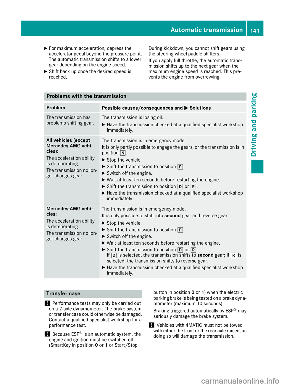
vents the engine from overrevving.Problems with the transmission
Problem
Possible causes/consequences and
0050 0050Solutions The transmission has
problems shifting gear. The transmission is losing oil.
X Have the transmission checked at a qualified specialist workshop
immediately. All vehicles (except
Mercedes-AMG vehi-
cles):
The acceleration ability
is deteriorating.
The transmission no lon-
ger changes gear. The transmission is in emergency mode.
It is only partly possible to engage the gears, or the transmission is in
position 005C.
X Stop the vehicle.
X Shift the transmission to position 005D.
X Switch off the engine.
X Wait at least ten seconds before restarting the engine.
X Shift the transmission to position 005Bor005E.
X Have the transmission checked at a qualified specialist workshop
immediately. Mercedes-AMG vehi-
cles:
The acceleration ability
is deteriorating.
The transmission no lon-
ger changes gear. The transmission is in emergency mode.
It is only possible to shift into
secondgear and reverse gear.
X Stop the vehicle.
X Shift the transmission to position 005D.
X Switch off the engine.
X Wait at least ten seconds before restarting the engine.
X Shift the transmission to position 005Bor005E.
If 005B is selected, the transmission shifts to secondgear; if005Eis
selected, the transmission shifts to reverse gear.
X Have the transmission checked at a qualified specialist workshop
immediately. Transfer case
! Performance tests may only be carried out
on a 2-axle dynamometer. The brake system
or transfer case could otherwise be damaged.
Contact a qualified specialist workshop for a
performance test.
! Because ESP ®
is an automatic system, the
engine and ignition must be switched off
(SmartKey in position 0or 1or Start/Stop button in position
0or 1) when the electric
parking brake is being tested on a brake dyna-
mometer (maximum 10 seconds).
Braking triggered automatically by ESP ®
may
seriously damage the brake system.
! Vehicles with 4MATIC must not be towed
with either the front or the rear axle raised, as
doing so will damage the transmission. Automatic transmission
141Driving and parking Z
Page 155 of 370
vehicle rectified immediately at a qualified spe-
cialist workshop.
Do not shift into transmission position 005Cwhen
driving off-road. You could lose control of the
vehicle if you attempt to brake the vehicle using
the service brake. If the gradient is too steep for
your vehicle, drive back down in reverse gear.
General notes H
Environmental note
Protection of the environment is of primary
importance. Treat nature with respect.
Observe all prohibiting signs.
Read this section carefully before driving your
vehicle off-road. Practice by driving over more
gentle off-road terrain first.
Familiarize yourself with the characteristics of
your vehicle and the gear shift operation before
driving through difficult terrain.
The following driving systems are specially
adapted to off-road driving:
R AIRMATIC package (vehicle level)
(Y page 168)
R DSR (Downhill Speed Regulation)
(Y page 167)
Observe the following notes:
R Select a vehicle level that is suitable for the
terrain. To avoid damaging the vehicle, make
sure there is always sufficient ground clear-
ance.
R Check that items of luggage and loads are
stowed safely and are well secured
(Y page 276).
R Always keep the engine running and in gear
when driving on a downhill gradient. Activate
DSR (Y page 167).
R Always keep the engine running and in gear
when driving down an incline.
R Adapt your speed to the terrain. The rougher,
steeper or more ruts on the terrain, the slower
your speed should be.
R Do not jump with the vehicle as this will inter-
rupt the vehicle's propulsion.
R Drive with extreme care on unfamiliar off-road
routes where visibility is poor. For safety rea- sons, get out of the vehicle first and survey
the off-road route.
R Look out for obstacles, such as rocks, holes,
tree stumps and furrows. R
Take care when turning on an uphill or down-
hill slope or when driving across a slope. The
vehicle could otherwise tip over.
R Always keep the doors, the tailgate, the side
windows and the sliding sunroof closed while
the vehicle is in motion.
R Do not shift the automatic transmission to
position 005C.
R Observe the notes on off-road fording
(Y page 151).
i Information about retrofitting special all-ter-
rain tires is available from any qualified spe-
cialist workshop.
i Do not use the HOLD function when driving
off-road, on steep uphill or downhill gradients
or on slippery or loose surfaces. The HOLD
function cannot hold the vehicle on such sur- faces.
Checklist before driving off-road !
If the engine oil warning lamp lights up while
the vehicle is in motion, stop the vehicle in a
safe place as soon as possible. Check the
engine oil level. The engine oil warning lamp
warning must not be ignored. Continuing the
journey while the symbol is displayed could
lead to engine damage.
X Engine oil level: check the engine oil level
and add engine oil if necessary.
When you drive on steep gradients, the engine
oil level must be sufficiently high to ensure
that oil is supplied correctly in the vehicle.
X Tire-changing tool kit: check that the jack is
working and make sure you have the lug
wrench, a robust tow cable and a folding
spade in the vehicle.
X Wheels and tires: check the tread depth and
pressure of the tires.
X Check for damage and remove any foreign
objects, e.g. small stones, from the wheels/
tires.
X Replace any missing valve caps.
X Replace dented or damaged wheels.
X Rims: dented or bent rims can result in a loss
of tire pressure and damage the tire bead.
Before driving off-road, check the wheels and replace them if necessary. Driving tips
153Driving and parking Z
Page 309 of 370
Interior care
Cleaning the display !
For cleaning, do not use any of the following:
R alcohol-based thinner or gasoline
R abrasive cleaning agents
R commercially-available household cleaning
agents
These may damage the display surface. Do
not put pressure on the display surface when cleaning. This could lead to irreparable dam-
age to the display.
X Before cleaning the display, make sure that it
is switched off and has cooled down.
X Clean the display surface using a commer-
cially available microfiber cloth and TFT/LCD
display cleaner.
X Dry the display surface using a dry microfiber
cloth.
Cleaning the plastic trim G
WARNING
Care products and cleaning agents containing solvents cause surfaces in the cockpit to
become porous. As a result, plastic parts may
come loose in the event of air bag deploy-
ment. There is a risk of injury.
Do not use any care products and cleaning
agents to clean the cockpit.
! Never attach the following to plastic surfa-
ces:
R stickers
R films
R perfume oil container or similar
You could otherwise damage the plastic.
! Do not allow cosmetics, insect repellent or
sunscreen to come into contact with the plas-
tic trim. This maintains the high-quality look of the surfaces.
X Wipe the plastic trim with a damp, lint-free
cloth, e.g. a microfiber cloth.
X Heavy soiling: use care and cleaning prod-
ucts recommended and approved by
Mercedes-Benz.
The surface may change color temporarily.
Wait until the surface is dry again. Cleaning the steering wheel and gear or
selector lever X
Thoroughly wipe with a damp cloth or use
leather care agents that have been recom-
mended and approved by Mercedes-Benz.
Cleaning genuine wood and trim ele-
ments !
Do not use solvent-based cleaning agents
such as tar remover, wheel cleaners, polishes
or waxes. There is otherwise a risk of damag- ing the surface.
! Do not use chrome polish on trim pieces.
The trim pieces have a chrome look but are
mostly made of anodized aluminum and can
lose their shine if chrome polish is used. Use
a damp, lint-free cloth instead when cleaning the trim pieces.
If the chrome-plated trim pieces are very
dirty, you can use a chrome polish. If you are
unsure as to whether the trim pieces are
chrome-plated or not, consult an authorized
Mercedes-Benz Center.
X Wipe the wooden trim and trim pieces with a
damp, lint-free cloth, e.g. a microfiber cloth.
X Heavy soiling: use car care and cleaning
products recommended and approved by
Mercedes-Benz.
Cleaning the seat covers General notes
! Do not use a microfiber cloth to clean covers
made out of real leather, artificial leather or
DINAMICA. If used often, these can damage
the cover.
i Note that regular care is essential to ensure
that the appearance and comfort of the cov-
ers is retained over time. Care
307Maintenance and care Z
Page 315 of 370
X
Do not remove any foreign objects which have
penetrated the tire, e.g. screws or nails.
X Remove the tire sealant bottle, the accompa-
nying TIREFIT sticker and the tire inflation
compressor from the stowage well under-
neath the cargo compartment floor
(Y page 310).
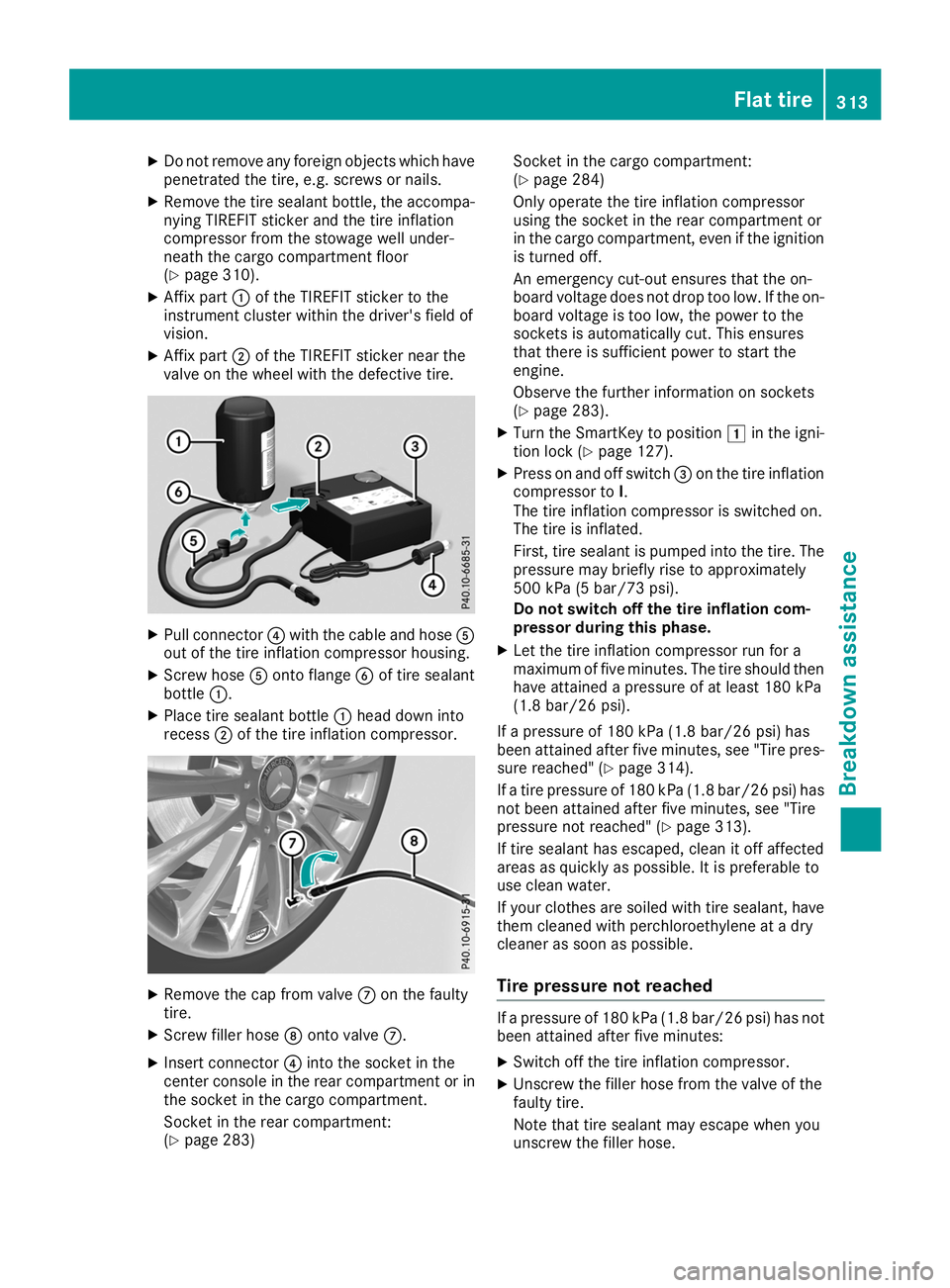
X Affix part 0043of the TIREFIT sticker to the
instrument cluster within the driver's field of
vision.
X Affix part 0044of the TIREFIT sticker near the
valve on the wheel with the defective tire. X
Pull connector 0085with the cable and hose 0083
out of the tire inflation compressor housing.
X Screw hose 0083onto flange 0084of tire sealant
bottle 0043.
X Place tire sealant bottle 0043head down into
recess 0044of the tire inflation compressor. X
Remove the cap from valve 006Bon the faulty
tire.
X Screw filler hose 006Conto valve 006B.
X Insert connector 0085into the socket in the
center console in the rear compartment or in
the socket in the cargo compartment.
Socket in the rear compartment:
(Y page 283) Socket in the cargo compartment:
(Y page 284)
Only operate the tire inflation compressor
using the socket in the rear compartment or
in the cargo compartment, even if the ignition
is turned off.
An emergency cut-out ensures that the on-
board voltage does not drop too low. If the on-
board voltage is too low, the power to the
sockets is automatically cut. This ensures
that there is sufficient power to start the
engine.
Observe the further information on sockets
(Y page 283).
X Turn the SmartKey to position 0047in the igni-
tion lock (Y page 127).
X Press on and off switch 0087on the tire inflation
compressor to I.
The tire inflation compressor is switched on.
The tire is inflated.
First, tire sealant is pumped into the tire. The
pressure may briefly rise to approximately
500 kPa (5 bar/73 psi).
Do not switch off the tire inflation com-
pressor during this phase.
X Let the tire inflation compressor run for a
maximum of five minutes. The tire should then have attained a pressure of at least 180 kPa
(1.8 bar/26 psi).
If a pressure of 180 kPa (1.8 ba r/26 psi) has
been at tained after five minutes, see "Tire pres-
sure reached" (Y page 314).
If a tire pressure of 180 kPa (1.8 bar/26 psi) has not been attained after five minutes, see "Tire
pressure not reached" (Y page 313).
If tire sealant has escaped, clean it off affected
areas as quickly as possible. It is preferable to
use clean water.
If your clothes are soiled with tire sealant, have them cleaned with perchloroethylene at a dry
cleaner as soon as possible.
Tire pressure not reached If a pressure of 180 kPa (1.8 bar/26 psi) has not
been attained after five minutes:
X Switch off the tire inflation compressor.
X Unscrew the filler hose from the valve of the
faulty tire.
Note that tire sealant may escape when you
unscrew the filler hose. Flat tire
313Breakdown assistance Z
Page 348 of 370
Recommended tire pressures
The recommended tire pressure applies to the
tires mounted at the factory.
The Tire and Loading Information placard con-
tains the recommended tire pressures for cold
tires on a fully loaded vehicle and for the maxi-
mum permissible vehicle speed.
The tire pressure table contains the recommen- ded pressures for cold tires for various operat-
ing conditions, i.e. differing load and speed con- ditions.
Increased vehicle weight due to optional
equipment
The combined weight of all standard and
optional equipment available for the vehicle,
regardless of whether it is actually installed on
the vehicle or not.
Rim This is the part of the wheel on which the tire is
mounted.
GAWR (Gross Axle Weight Rating)
The GAWR is the maximum gross axle weight
rating. The actual load on an axle must never
exceed the gross axle weight rating. The gross
axle weight rating can be found on the vehicle
identification plate on the B-pillar on the driver's side.
Speed rating
The speed rating is part of the tire identification. It specifies the speed range for which the tire isapproved.
GTW (Gross Trailer Weight)
The GTW is the weight of a trailer including the
weight of the load, luggage, accessories etc. on the trailer.
GVW (Gross Vehicle Weight) The gross vehicle weight includes the weight of
the vehicle including fuel, tools, the spare wheel, accessories installed, occupants, luggage and
the drawbar noseweight, if applicable. The gross vehicle weight must not exceed the gross vehi-
cle weight rating GVWR as specified on the vehi-
cle identification plate on the B-pillar on the
driver's side. GVWR (Gross Vehicle Weight Rating)
The GVWR is the maximum permissible gross
weight of a fully loaded vehicle (the weight of the
vehicle including all accessories, occupants,
fuel, luggage and the drawbar noseweight, if
applicable). The gross vehicle weight rating is
specified on the vehicle identification plate on
the B-pillar on the driver's side.
Maximum loaded vehicle weight
The maximum weight is the sum of:
R the curb weight of the vehicle
R the weight of the accessories
R the load limit
R the weight of the factory installed optional
equipment
Kilopascal (kPa) Metric unit for tire pressure. 6.9 kPa corre-
sponds to 1 psi. Another unit for tire pressure is
bar. 100 kilopascals (kPa) are the equivalent of
1 bar.
Load index
In addition to the load-bearing index, the load
index may also be imprinted on the sidewall of
the tire. This specifies the load-bearing capacity more precisely.
Curb weight
The weight of a vehicle with standard equipment
including the maximum capacity of fuel, oil and
coolant. It also includes the air-conditioning sys- tem and optional equipment if these are instal-
led in the vehicle, but does not include passen-
gers or luggage.
Maximum load rating
The maximum tire load is the maximum permis- sible weight in kilograms or lbs for which a tire is
approved.
Maximum permissible tire pressure
Maximum permissible tire pressure for one tire.
Maximum load on one tire
Maximum load on one tire. This is calculated by
dividing the maximum axle load of one axle by
two. 346
All about wheels and tiresWheels and tires
Page 350 of 370
ponents may also be damaged. There is a risk
of an accident.
Rotate front and rear wheels only if the wheels
and tires are of the same dimensions.
! On vehicles equipped with a tire pressure
monitor, electronic components are located
in the wheel.
Tire-mounting tools should not be used near
the valve. This could damage the electronic
components.
Only have tires changed at a qualified spe-
cialist workshop.
Always observe the instructions and safety
notes in the "Mounting a wheel" section
(Y page 348).
The wear patterns on the front and rear tires
differ, depending on the operating conditions.
Rotate the wheels before a clear wear pattern
has formed on the tires. Front tires typically
wear more on the shoulders and the rear tires in
the center.
On vehicles that have the same size front and
rear wheels, you can rotate the wheels accord-
ing to the intervals in the tire manufacturer's
warranty book in your vehicle documents. If no
warranty book is available, the tires should be
rotated every 3,000 to 6,000 miles (5,000 to
10,000 km). Depending on tire wear, this may
be required earlier. Do not change the direction
of wheel rotation.
Clean the contact surfaces of the wheel and the brake disc thoroughly every time a wheel is rota-
ted. Check the tire pressure and, if necessary,
restart the tire pressure loss warning system or
the tire pressure monitor (Y page 334).Direction of rotation
Tires with a specified direction of rotation have
additional benefits, e.g. if there is a risk of hydro-
planing. These advantages can only be gained if the tires are installed corresponding to the
direction of rotation.
An arrow on the sidewall of the tire indicates its
correct direction of rotation. Storing wheels
Store wheels that are not being used in a cool,
dry and preferably dark place. Protect the tires
from oil, grease, gasoline and diesel. Mounting a wheel
Preparing the vehicle X
Vehicle with emergency spare wheel:
when mounting the emergency spare wheel in
the event of a flat tire, follow the additional
notes on vehicle preparation under "Flat tire" (Y page 310).
X Stop the vehicle on solid, non-slippery and
level ground.
X Apply the electric parking brake manually.
X Bring the front wheels into the straight-ahead
position.
X Vehicles with automatic transmission:
shift the transmission to position
005D.
X Vehicles with the AIRMATIC package:
make sure that the normal vehicle level is
selected (Y page 170).
X Switch off the engine.
X Vehicles without KEYLESS-GO: remove the
SmartKey from the ignition lock.
X Vehicles with KEYLESS-GO: open the driv-
er's door.
The vehicle electronics are now in position
0092. This means no SmartKey is in the ignition lock.
X Vehicles with KEYLESS-GO: remove the
Start/Stop button from the ignition lock
(Y page 127).
X Make sure that the engine cannot be started
via your smartphone (Y page 129).
X If included in the vehicle equipment, remove
the tire-change tool kit from the vehicle.
X Safeguard the vehicle against rolling away.
i Apart from certain country-specific varia-
tions, vehicles are not equipped with a tire-
change tool kit. For more information on
which tools are required to perform a wheel
change on your vehicle, consult a qualified
specialist workshop. 348
Changing a wheelWheels and tires