2019 MERCEDES-BENZ EQC SUV charging
[x] Cancel search: chargingPage 371 of 629
In
this lane, you will not be able tocompl ete
th e next change of direction without chang‐
ing lane.
During thech ange of direction, new lanes may
be added.
Bus lanes are also shown.
% Lane recommendations can also be dis‐
pl ay ed in the Instrument Display and in the
Head-up Displa y.
Using mo torw ay information
Re quirements:
R The Motorway information option is switched
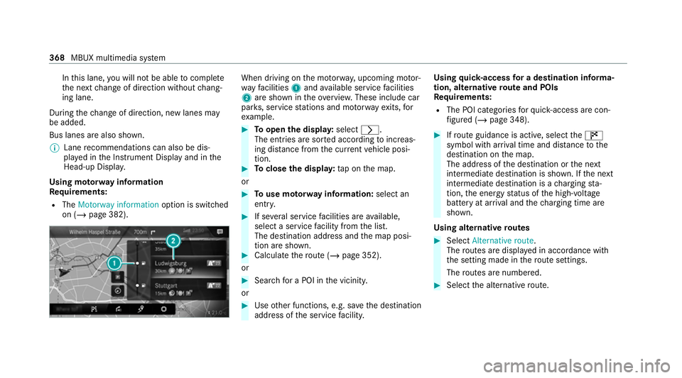
on (/ page 382). When driving on
the mo torw ay, upcoming mo tor‐
wa yfa cilities 1and available service facilities
2 are shown in theove rview. These include car
par ks, service stations and mo torw ay ex its,for
ex ample. #
Toopen the displa y:select r.
The entries are sor ted according toinc reas‐
ing dis tance from the cur rent vehicle posi‐
tion. #
Toclose the displa y:tap on the map.
or #
Touse mo torw ay information: select an
ent ry. #
If se veral service facilities are available,
select a service facility from the list.
The destination address and the map posi‐
tion are shown. #
Calculate thero ute (/ page 352).
or #
Sea rchfo r a POI in the vicinit y.
or #
Use other functions, e.g. sa vethe destination
address of the service facility. Using
quick- access for a destination in form a‐
tion, alternative route and POIs
Re quirements:
R The POI categories forqu ick- access are con‐
fi gured (/ page 348). #
Ifro ute guidance is active, select the£
symbol with ar riva l time and dis tance tothe
destination on the map.
The address of the destination or the next
intermediate destination is shown. If the next
intermediate destination is a charging sta‐
tion, the energy status of the high-voltage
battery at ar riva l and thech arging time are
shown.
Using alternative routes #
Select Alternative route .
The routes are displ ayed in accordance with
th e setting made in thero ute settings.
The routes are numbered. #
Select the alternative route. 368
MBUX multimedia sy stem
Page 483 of 629
#
Drive tothe nearest qualified specialist work‐
shop and ha vethe tyre, tyre sealant bottle
and filling hose replaced there. Batte
ry(vehicle) Note
s onthe12 V battery &
WARNING Risk of an accident due to
wo rkcar ried out incor rectly on the bat‐
te ry
Wo rkcar ried out incor rectly on the battery
can, forex ample, lead toa short circuit. This
can lead tofunction restrictions in saf ety-re l‐
eva nt sy stems, e.g. the lighting sy stem, ABS
(anti-lock braking sy stem) or ESP ®
(Elec‐
tronic Stability Prog ram). The operating
saf ety of your vehicle may be restricted.
Yo u could lose cont rol of theve hicle in the
fo llowing situations:
R when braking
R intheeve nt of ab rupt steering manoeu‐
vres and/or when theve hicle's speed is
not adap tedto thero ad conditions #
Intheeve nt of a sho rtcircuit or a simi‐
lar incident, contact a qualified special‐
ist workshop immediately. #
Do not continue driving. #
Alw ays ha vewo rkon the battery car ried
out at a qualified specialist workshop. R
Further information on ABS (/ page198)
R Further information on ESP ®
(/ page 198)
Fo r saf etyre asons, Mercedes-Benz recommends
th at you on lyuse bat teries which ha vebeen tes‐
te d and appr ovedfo ryo ur vehicle byMercedes-
Benz. These batteries pr ovide inc reased impact
pr otection topreve ntvehicle occupants from
suf fering acid bu rns should the battery be dam‐
aged in theeve nt of an accident. &
WARNING Risk ofexplosion due toelec‐
tros tatic charge
Electros tatic charge can cause spa rks which
may ignite the highly flammable gas mixture
in the batter y. #
Todischar geany electros tatic charge
th at may ha vebuilt up, touch the me tal ve
hicle body before handling the bat‐
te ry. The highly
flammable gas mixture is created
while the battery is charging and during starting
assis tance. &
WARNING Danger of chemical burns
from the battery acid
Battery acid is caustic. #
Avoid contact with the skin, eyes or
clo thing. #
Do not lean overth e batter y. #
Do not inhale battery gases. #
Keep children away from the batter y. #
Immedia tely rinse battery acid off thor‐
oughly with plenty of clean water and
seek medical attention immediately. 480
Breakdown assi stance
Page 485 of 629
#
Lea vethe danger zone immediatel y.
Secu rethe danger zone at a suf ficient
di st ance. #
Call thefire service. In order
forth e high-voltage battery toachie ve
th e maximum possible service life, it should
alw ays be suf ficiently charge d. Ha vethe bat‐
te ry 's ch arge leve lch ecked if you park theve hi‐
cle for a long period of time. Exhaustive dis‐
ch arging caused bytheve hicle standing idle for
lengt hyperiods can damage the high-voltage
batter y.Ifth eve hicle is idle for lengt hyperiods,
ru n it for a few minutes once everyfour we eks to
ch arge up the high-voltage batter y. Risk of
explosion. Fire, naked
flames and smoking are
prohibi ted when handling the batter y.
Av oid creating spar ks. Electrolyte
or battery acid is cor ro‐
sive. Avoid contact with the skin, eyes
or clo thing. Wear suitable pr otective
clo thing, in particular glove s, an
apron and a face mas k.Immedia tely
ri nse electrolyte or acid splashes off
with clean water.Consult a doc tor if
necessar y. We
ar saf etygl asses. Ke
ep children away. Obser
vethis Owner's Manual.
Fu rther information on charging the high-voltage
battery (/ page175). St
arting assi stance and charging the12 V
battery #
Only ha vestarting assis tance pr ovided by a
qu alified specialist workshop, e.g. a
Mercedes-Benz Service Centre. #
Only ha vethe battery charge d at a qualified
specialist workshop, e.g. a Mercedes-Benz
Service Centre. Re
placing the 12V battery #
Only ha vethe battery replaced at a qualified
specialist workshop, e.g. at a Mercedes-Benz
Service Centre. To
w- starting or towing away Pe
rm itted towing me thods Mercedes-Benz
recommends transporting your
ve hicle in the case of a breakdown, rath er than
to wing it away.
Fo rto wing, use a tow rope or tow bar with bo th
axles on the ground. Do not use tow bar sys‐
te ms. 482
Breakdown assi stance
Page 520 of 629
Ro
of load EQC 400 4MATIC
Maximum
roof load 75kg Te
ch nical data of the high-voltage bat tery Missing
values werenot available at the time of
going topress.
High-voltage battery EQC 400 4MATIC
Ty
pe Lithium-ion
Battery energy con tent
(NEDC) 80 kWh
Ra nge
Charge time – mode 4
wi th appr ox.11 0 kW peak
ch arging capacity App
rox.
40 min
Charge time – mode 3
wi th 7.4 kW charging capacity App
rox. 11 h EQC 400 4MATIC
Char
getime – mode 2
wi th 3.7 kW charging capacity App
rox. 21 h
30 min
Charge time – mode 2
with 2.3 kW charging capacity App
rox. 40 h
45 min
Charge time – mode 2
wi th 1.8 kW charging capacity App
rox. 53 h
15 min The
charge times – modes 2 and 3 are forch arg‐
ing from 10%to 100% of the usable battery capa‐
city with alternating cur rent.
The charge time – mode 4 is forch arging from
10 %to 80% of the usable battery capacity with
direct cur rent.
The charging capacity de term ines thech arge
time, in addition tothe battery charge status and
th e ambient temp erature. The charging capacity
depends on the supply voltage, the cur rent
intensity and the type of po wer supp ly. Tr
ailer hitch Gene
ral no tes on the trailer hit ch Modifications
tothe engine cooling sy stem may
be necessar y,depending on theve hicle model.
The retrofitting of a trailer hitch is only pe rmissi‐
ble if a towing capacity is specified in your vehi‐
cle documents.
Fu rther information can be obtained at a quali‐
fi ed specialist workshop. Te
ch nical da ta517
Page 559 of 629
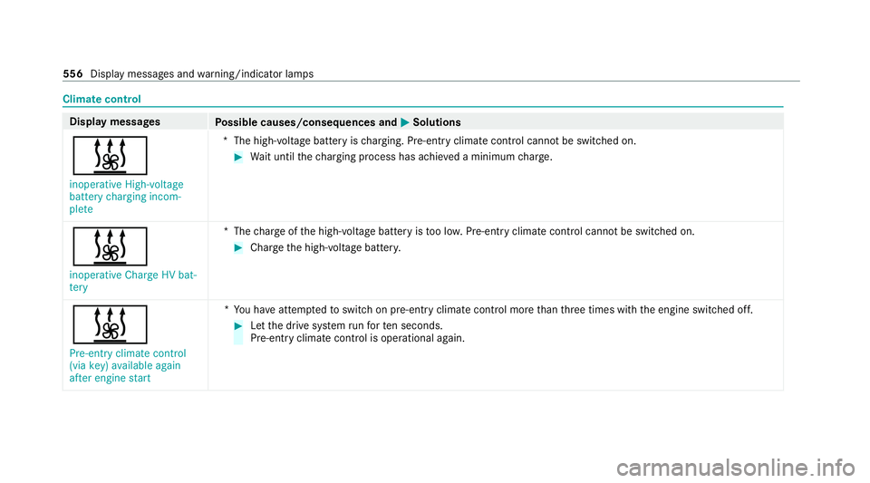
Climate control
Displ
aymessages
Possible causes/consequences and M
MSolutions
& inoperative High-voltage
battery charging incom-
plete *T
he high-voltage battery is charging. Pre-ent ryclimate control cannot be switched on. #
Wait until thech arging process has achie ved a minimum charge.
& inoperative Charge HV bat-
tery *T
hecharge ofthe high-voltage battery is too lo w.Pre-ent ryclimate control cannot be switched on. #
Charge the high-voltage batter y.
& Pre-entry climate control
(via key) available again
after engine start *Y
ou ha veattem ptedto switch on pre-entry climate contro l morethan thre e times with the engine switched off. #
Let the drive sy stem runfo rte n seconds.
Pre-entry clima tecontrol is ope rational again. 556
Displaymessa ges and warning/indicator lamps
Page 561 of 629
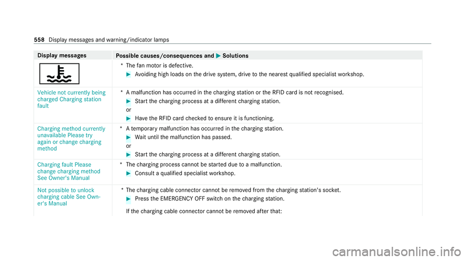
Display messages
Possible causes/consequences and M
MSolutions
? *T
hefan mo tor is defective. #
Avoiding high loads on the drive sy stem, drive tothe nearest qualified specialist workshop.
Vehicle not currently being
charged Charging station
fault *A
malfunction has occur red in thech arging station or the RFID card is not recognised. #
Start thech arging process at a dif fere nt charging station.
or #
Have the RFID card checkedto ensure it is functioning.
Charging method currently
unavailable Please try
again or change charging
method *A
temp orary malfunction has occur red in thech arging station. #
Wait until the malfunction has passed.
or #
Start thech arging process at a dif fere nt charging station.
Charging fault Please
change charging method
See Owner's Manual *T
hecharging process cannot be star ted due toa malfunction. #
Consult a qualified specialist workshop.
Not possible to unlock
charging cable See Own-
er's Manual *T
hecharging cable connec tor cannot be remo ved from thech arging station's soc ket. #
Press the EMERG ENCY OFF switch on thech arging station.
If th ech arging cable connec tor cannot be remo ved af terth at: 558
Display messages and warning/indicator lamps
Page 570 of 629
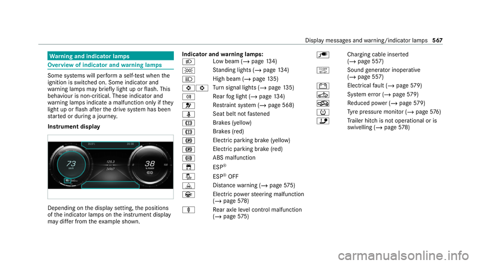
Wa
rning and indicator lamps Overview of indicator and
warning lamps Some sy
stems will per form a self-test when the
ignition is switched on. Some indicator and
wa rning lamps may briefly light up or flash. This
behaviour is non-critical. These indicator and
wa rning lamps indicate a malfunction only if they
light up or flash af terth e drive sy stem has been
st ar ted or during a journe y.
Instrument display Depending on
the display setting, the positions
of the indicator lamps on the instrument display
may dif fer from theex ample shown. Indicator and
warning lamps:
L Low beam (/
page134)
T St
anding lights (/ page134)
K High beam (/
page135)
#! Tu
rn signal lights (/ page135)
R Re
ar fog light (/ page134)
6 Re
stra int sy stem (/ page 568)
ü Seat belt not
fastened
J Brakes (yellow)
J Brakes (red)
! Elect
ric pa rking brake (yellow)
! Electric parking brake (red)
! ABS malfunction
÷ ESP®
å ESP®
OFF
L Distance warning (/ page575)
Ù Electric powerst eering malfunction
(/ page 578)
ä Rear axle le vel control malfunction
(/ page 575) è
Charging cable inser
ted
( / page 557)
ò Soundgenerator inope rative
(/ page 557)
# Electrical
fault (/ page579)
Ú Sy
stem er ror (/ page579)
O Reduced po wer (/ page579)
h Ty
re pressure monitor (/ page576)
ï Trailer hit chis not operational or is
swivelling (/ page578) Displ
aymessa ges and warning/indicator lamps 567
Page 587 of 629
Assistance
Menu (on-board co mputer) .................. 268
Assistance sy stems
see Driving saf ety sy stem
ASS YST PLUS ........................................... 459
Battery disconnection pe riods .............4 59
Displ aying the service due date ........... 459
Fu nction/no tes ................................... 459
Re gular maintenance work .................. 459
Special service requirements .............. 459
ATA (anti-theft ala rmsystem) .................. 96
Deactivating the alarm .......................... 97
Fu nction ................................................ 96
Fu nction of interior pr otection ............... 97
Priming/deactivating interior pr otec‐
tion ........................................................ 98
Priming/deactivating tow- aw ay pro‐
te ction ................................................... 97
To w- aw ay protection function ................97
AT TENTION ASSI ST.......................... 245, 24 6
Fu nction .............................................. 24 5
Setting ................................................. 24 6
Sy stem limitations ...............................2 45At
tention assistant
see ATTENTION ASSIST
Au gmented reality
see Route guidance with augmented reality
Au thorised workshop
see Qualified specialist workshop
Au tomatic distance control
see Active Dis tance Assi stDISTRONIC
Au tomatic driving lights .........................13 5
Au tomatic front passen ger front air‐
bag deacti vation sy stem
see Automatic front passenger front
airbag shutoff
Au tomatic front passen ger front air‐
bag shu toff ........................................... 40, 41
Fu nction of the automatic front
passenger front airbag deactivation
sy stem ................................................... 40
PA SSENGER AIR BAG indicator lamp .... .41
Au tomatic mir rorfo lding function
Ac tivating/deactivating ...................... .149
Au tomatic seat adjustment
Setting ................................................ .105 Au
tomatic transmission
Engaging neutral .................................. 174
Axle load Perm issible .......................................... 511
Tr ailer operation .................................. .519 B
Bag hook .................................................. 12 2
Ball ne ck
Extending/r etra cting ........................... 256
BA S (Brake Assist Sy stem) .................... .198
Battery Key ........................................................ .74
Battery see Battery (vehicle)
see High-vol tage battery
Batte ry(high-voltage on-boa rdelectri‐
cal sy stem)
see High-voltage battery
Battery (vehicle) ...................................... 482
Charging .............................................. 482
No tes .................................................. 480
Re placing ............................................ 482 584
Index