2019 MASERATI QUATTROPORTE stop start
[x] Cancel search: stop startPage 88 of 396

Cleaning the Park Assist
Sensors When cleaning the sensors, take
special care not to scratch or damage
them; therefore, do not use dry, rough
or hard cloths.
The sensors must be washed with clean
water, possibly adding car shampoo.
Should you need to repaint the
bumper or in case of paint touch-ups
in the sensor area, please contact
exclusively the Authorized Maserati
Dealer . Incorrect paint application
could affect the parking sensors
operation. Park Assist System Usage
Precautions NOTE:
• Jackhammers, large trucks, and other
vibrations could affect the
performance of Park Assist.
• Objects such as bicycle carriers, trailer
hitches, etc., must not be placed
within 12 in (30 cm) from the rear
bumper while driving the vehicle.
Failure to do so can result in the
system misinterpreting a close object
as a sensor problem, causing the
service Park Assist message to be
displayed in the instrument cluster.
CAUTION!
• Park Assist is only a parking aid and
it is unable to recognize every
obstacle, including small obstacles.
Parking curbs might only be
temporarily detected or not detected
at all. Obstacles located above or
below the sensors will not be
detected when they are in close
proximity.
• The vehicle must be driven slowly
when using Park Assist in order to be
able to stop in time when an
obstacle is detected. When backing up, it is recommended that the driver
looks over his/her shoulder when
using Park Assist.
WARNING!
Drivers must be careful when backing
up even when using the Park Assist
system. Always check carefully behind
your vehicle, look behind you, and be
sure to check for pedestrians, animals,
other vehicles, obstructions, and blind
spots before backing up. You are
responsible for safety and must
continue to pay attention to your
surroundings. Failure to do so can
result in serious injury or death.
Park Assist Volume The volume of the acoustic signal
emitted by the front and rear parking
sensors is set to the medium level.
Three different levels of volume can be
selected via the submenu “Safety &
Driving Assistant” from the MTC+
System.
Low level is useful in certain conditions
when the parking sensor acoustic
signal keeps coming on although there
is no actual collision hazard. This may
typically occur when driving in a queueBefore Starting
2
84
Page 90 of 396
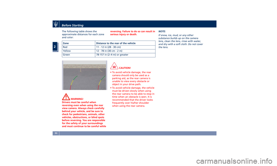
The following table shows the
approximate distances for each zone
and color:
WARNING!
Drivers must be careful when
reversing even when using the rear
view camera. Always check carefully
behind your vehicle, and be sure to
check for pedestrians, animals, other
vehicles, obstructions, or blind spots
before reversing. You are responsible
for the safety of your surroundings
and must continue to be careful while reversing. Failure to do so can result in
serious injury or death.
CAUTION!
• To avoid vehicle damage, the rear
camera should only be used as a
parking aid, as the rear camera is
unable to view every obstacle or
object in your drive path.
• To avoid vehicle damage, the vehicle
must be driven slowly when using
the rear camera to be able to stop in
time when an obstacle is seen. It is
recommended that the driver looks
frequently over his/her shoulder
when using the rear camera. NOTE:
If
snow ,
ice, mud, or any other
substance builds up on the camera
lens, clean the lens, rinse with water,
and dry with a soft cloth. Do not cover
the lens.Zone Distance to the rear of the vehicle
Red 11-12in(28-30cm)
Yellow 12 - 78 in (30 c m-2m)
Green 78-157 in (2–4 m) or greaterBefore Starting
2
86
Page 93 of 396
cameras are unable to view every
obstacle or object in your drive path.
• To avoid vehicle damage, the vehicle
must be driven slowly when using
the camera system with surround
view, to be able to stop in time
when an obstacle is seen. It is
recommended that the driver looks
frequently over his/her shoulder
when using this system.
NOTE:
If
snow , ice, mud, or any other
substance builds up on the camera
lens, clean the lens, rinse with water,
and dry with a soft cloth. Do not cover
the lens.
WARNING!
California Proposition 65
Operating, servicing and maintaining
a passenger vehicle or off-road vehicle
can expose you to chemicals including
such as, engine exhaust, carbon
monoxide, phthalates and lead, that
which are known to the State of
California to cause cancer and birth
defects or other reproductive harm. To
minimize exposure, avoid breathing
exhaust, do not idle the engine except as necessary, service your vehicle in a
well-ventilated area and wear gloves
or wash your hands frequently when
servicing your vehicle. For more
information go to:
www.P65Warnings.ca.gov/passenger-
vehicle
Safety Tips Transporting Passengers WARNING!
• Do not leave children or animals
inside parked vehicles in hot
weather. Interior heat build-up may
cause serious injury.
• Never ride in a cargo area, inside of
a vehicle.
• Do not allow people to ride in any
area of your vehicle that is not
equipped with seats and seat belts.
• Be sure everyone in your vehicle is
in a seat and using a seat belt
properly.Before Starting
2
89
Page 99 of 396

1 Adjustable side air outlets.
2 Engine START/STOP button.
3 Light switch.
4 Light dimmer controls.
5 Steering wheel controls.
6 Instrument cluster.
7* Right shift paddle +.
8* Left shift paddle –.
9 Hood release.
10 Adjustable central air outlets.
11 Analog clock.
12 MTC+ display.
13 Multifuction lever (windshield
wipers, headlight selection and
turn signals).
14 Climate controls.
15 Dashboard glove box handle.
16 Dashboard glove box.
17 Cover for compartment with
AUX, USB, SD memory card
port and slide phone drawer.
18 Storage compartment handle.
19 Storage compartment.
20 Vehicle security light and solar
sensor.
21 Internal rear view mirror. 22 Auto-dimming on/off button.
23 Front dome console.
(*) If equipped.
Central Console Components 1 Automatic transmission shift
lever.
2 Hazard lights switch.
3 Drive mode switches.
4 Electric Parking Brake lever.
5 Glove compartment.
6 Unlock button for central
console with cupholder and
power outlet.
7 Rotary selectors and buttons
foe the multimedia navigation.
8 Cover for cupholder and power
socket compartment.
9 Central console covers with
armrest function.
10 Air outlets (adjustable).
11 Rear power sunshade and rear
seats comfort controls panel.
12 Storage compartment.
13 Rear climate controls panel for
four-zone air conditioner
(optional).A/C Dual – zone
A/C Four – zone Understanding the Vehicle
3
95
Page 107 of 396

Easy Entry/Exit Driver Seat This feature provides automatic driver
seat positioning to enhance driver
mobility when entering and exiting
the vehicle.
The distance the driver seat moves
depends on where you have the driver
seat positioned when you place the
ignition device to the OFF position.
• When you cycle the ignition to the
OFF position the driver seat:
• will move about 2.36 in (60 mm)
rearward if the driver seat position
is greater than or equal to ca. 2.67
in (68 mm) forward of the rear
stop;
• will move to a position of ca.
0.31 in (8 mm) forward of the rear
stop if the driver seat position is
between 0.9 in (23 mm) and
2.67 in (68 mm) forward of the
rear stop.
• The seat will return to its previously
set position when you place the
ignition into the ACC or RUN
position.
• The Easy Entry/Easy Exit feature is
disabled when the driver seat
position is less than 0.9 in (23 mm)
forward of the rear stop. In this
position, there would be no benefit to the driver by moving the seat for
Easy Exit or Easy Entry.
Each stored memory setting will have
an associated Easy Entry and Easy Exit
position.
NOTE:
The Easy Entry/Easy Exit feature can be
enabled or disabled using the MTC+
System, refer to “MTC Settings” in
section “Dashboard Instruments and
Controls” for further information.
Rear Seats Rear seats can fit three passengers.
Seats, head restraints and seat belts
are parts of the occupant restraint
system of the vehicle.
For further information, see chapter
“Occupants Restraint Systems” in
section “Before Starting” and “Head
Restraints” in this section.
WARNING!
Be sure everyone in your vehicle is in
a seat and using a seat belt properly.
NOTE:
For vehicles equipped
with “Comfort
Luxury” rear seats with rear console
storage compartment, refer to chapter
“Comfort Luxury Rear Seats” in this
section.
Rear Armrest The rear armrest is mobile and can be
folded up into the seat back.
• To lower it, pull the stripe as
indicated.Understanding the Vehicle
3
103
Page 143 of 396
Cargo Area WARNING!
To help protect against personal
injury, passengers must not be seated
in the rear cargo area. The rear cargo
space is intended for load carrying
purposes only, not for passengers,
who should sit in seats and use seat
belts.
Vehicle Load Carrying Capacity The load carrying capacity of your
vehicle is shown on the vehicle
emission control label positioned on
the rear driver door's ledge.
The information indicated on the label
concerns passengers and luggage
loading operations. Do not exceed the specified Gross
Vehicle Weight Rating (GVWR) or the
Gross Axle Weight Rating (GAWR),
both front and rear.
The GVWR is the total allowable
weight of your vehicle. This includes
driver, passengers, and cargo.
The total load must be limited so that
you do not exceed the GVWR
indicated on the label.
Vehicle Loading WARNING!
• Improper weight distribution can
have an adverse effect on the way
the vehicle steers, handles and the
way the brakes operate.
• Never drive with the trunk lid open.
Exhaust gases can enter the
passenger compartment.
• Do not pile luggage or cargo higher
than the top of the seatback. This
could impair visibility or become
dangerous in a sudden stop or
collision.
The trunk is the most suitable place to
load
bulky and heavy objects onboard
the vehicle. The maximum allowable load on the floor of the trunk is 440 lb
(200 kg).
To load your vehicle properly, store
heavier items below and be sure you
distribute their weight as evenly as
possible.
Stow all loose items securely before
start driving as they could move
during the trip.
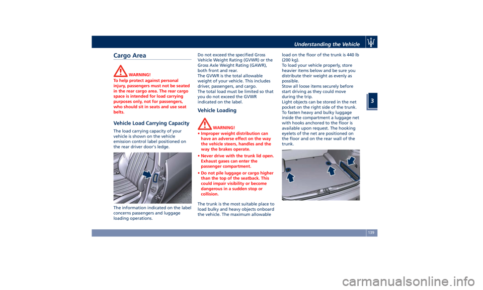
Light objects can be stored in the net
pocket on the right side of the trunk.
To fasten heavy and bulky luggage
inside the compartment a luggage net
with hooks anchored to the floor is
available upon request. The hooking
eyelets of the net are positioned on
the floor and on the rear wall of the
trunk.Understanding the Vehicle
3
139
Page 147 of 396
open, then adjust the sunroof opening
to minimise the buffeting.
Ignition Off Operation The power sunroof controls will
remain active for up to approximately
ten minutes after the ignition switch is
in OFF position. Opening either front
door will cancel this feature. The
ignition system timing can be set using
the MTC+ System (see “MTC+
Settings” in section “Dashboard
Instruments and Controls”).
Sunroof Maintenance Use only a nonabrasive cleaner and a
soft cloth to clean the glass panel. HomeLink ®
(optional) HomeLink ®
replaces up to three
hand-held transmitters operating the
automatic devices that open garage
doors and gates, enable/disable the
lighting or security systems. The
HomeLink ®
unit is powered by your
vehicle's 12 Volt battery. The
HomeLink ®
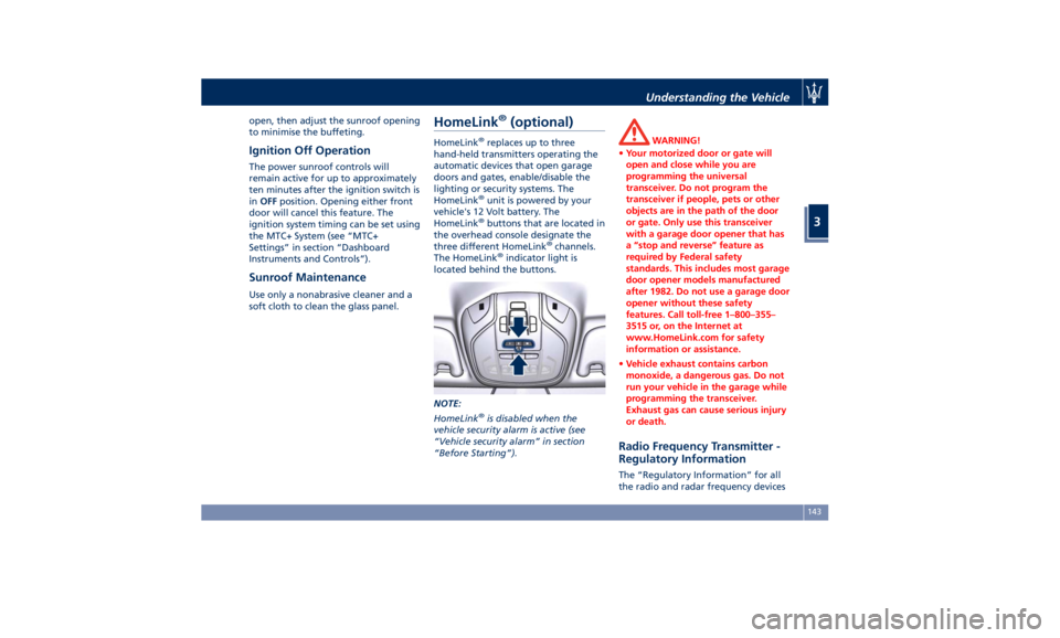
buttons that are located in
the overhead console designate the
three different HomeLink ®
channels.
The HomeLink ®
indicator light is
located behind the buttons.
NOTE:
HomeLink ®
is disabled when the
vehicle security alarm is active (see
“Vehicle security alarm” in section
“Before Starting”). WARNING!
• Your motorized door or gate will
open and close while you are
programming the universal
transceiver. Do not program the
transceiver if people, pets or other
objects are in the path of the door
or gate. Only use this transceiver
with a garage door opener that has
a “stop and reverse” feature as
required by Federal safety
standards. This includes most garage
door opener models manufactured
after 1982. Do not use a garage door
opener without these safety
features. Call toll-free 1–800–355–
3515 or, on the Internet at
www.HomeLink.com for safety
information or assistance.
• Vehicle exhaust contains carbon
monoxide, a dangerous gas. Do not
run your vehicle in the garage while
programming the transceiver.
Exhaust gas can cause serious injury
or death.
Radio Frequency Transmitter -
Regulatory Information The “Regulatory Information” for all
the radio and radar frequency devicesUnderstanding the Vehicle
3
143
Page 159 of 396
possible to have the problem
diagnosed and serviced.
NOTE:
Each time the ignition switch is in
RUN :
• The ESC OFF indicator light and
the ESC activation/malfunction
indicator light illuminates
temporarily.
• When the ESC is functioning, the
system will make buzzing or clicking
sounds. This is normal. The sounds
will stop once ESC becomes inactive
and the road conditions that caused
the ESC activation no longer persist.
Electronic Stability Control (ESC) OFF
Indicator Light
This indicator notifies that the
Electronic Stability Control
(ESC) is disabled; the linked
message will be displayed.
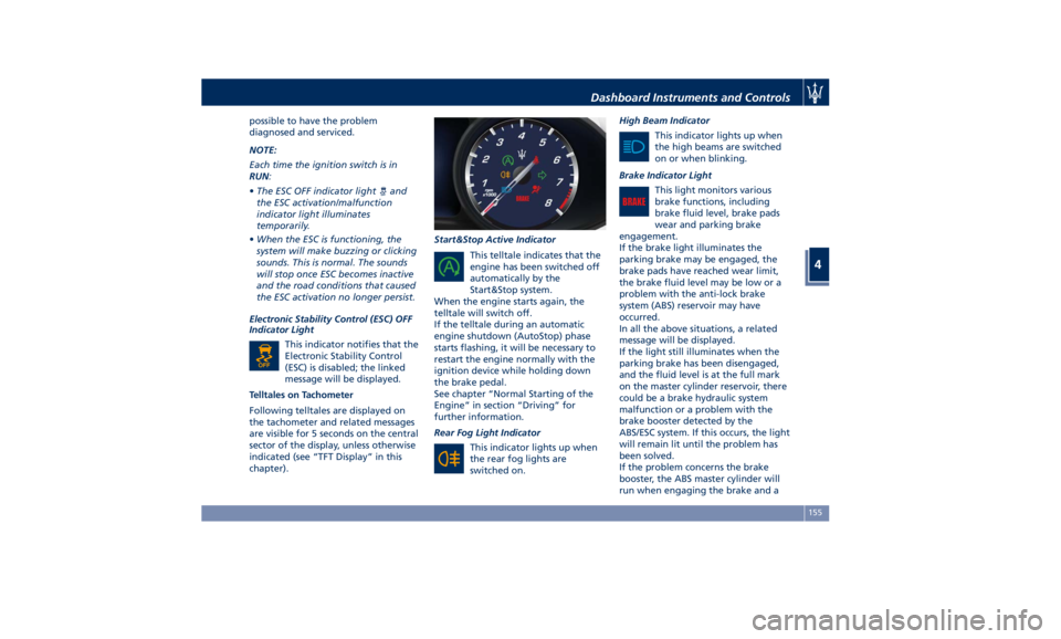
Telltales on Tachometer
Following telltales are displayed on
the tachometer and related messages
are visible for 5 seconds on the central
sector of the display, unless otherwise
indicated (see “TFT Display” in this
chapter). Start&Stop Active Indicator
This telltale indicates that the
engine has been switched off
automatically by the
Start&Stop system.
When the engine starts again, the
telltale will switch off.
If the telltale during an automatic
engine shutdown (AutoStop) phase
starts flashing, it will be necessary to
restart the engine normally with the
ignition device while holding down
the brake pedal.
See chapter “Normal Starting of the
Engine” in section “Driving” for
further information.
Rear Fog Light Indicator
This indicator lights up when
the rear fog lights are
switched on. High Beam Indicator
This indicator lights up when
the high beams are switched
on or when blinking.
Brake Indicator Light
This light monitors various
brake functions, including
brake fluid level, brake pads
wear and parking brake
engagement.
If the brake light illuminates the
parking brake may be engaged, the
brake pads have reached wear limit,
the brake fluid level may be low or a
problem with the anti-lock brake
system (ABS) reservoir may have
occurred.
In all the above situations, a related
message will be displayed.
If the light still illuminates when the
parking brake has been disengaged,
and the fluid level is at the full mark
on the master cylinder reservoir, there
could be a brake hydraulic system
malfunction or a problem with the
brake booster detected by the
ABS/ESC system. If this occurs, the light
will remain lit until the problem has
been solved.
If the problem concerns the brake
booster, the ABS master cylinder will
run when engaging the brake and aDashboard Instruments and Controls
4
155