Page 322 of 396

Inflation Pressure” in section
“Features and Specifications”) and
screw the cap on the compact spare
wheel valve.
CAUTION!
• In order to obtain a more accurate
reading, the compressor should be
switched off when checking the tire
pressure of the compact spare wheel
on the pressure gauge.
• Do not run the compressor for more
than 20 minutes: there is a risk it
could overheat. Also, prolonged
power absorption may discharge the
battery, subsequently preventing the
engine from starting.
• The compressor has been designed
exclusively to inflate compact spare wheels; do not use it to inflate air
mattresses, floatation devices, etc.
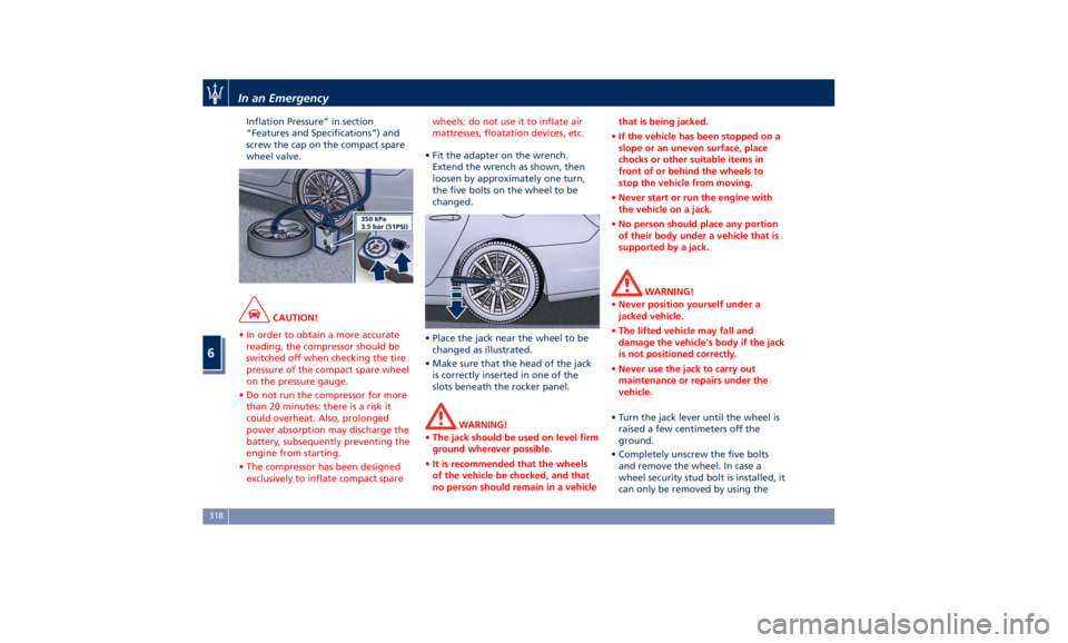
• Fit the adapter on the wrench.
Extend
the wrench as shown, then
loosen by approximately one turn,
the five bolts on the wheel to be
changed.
• Place the jack near the wheel to be
changed as illustrated.
• Make sure that the head of the jack
is correctly inserted in one of the
slots beneath the rocker panel.
WARNING!
• The jack should be used on level firm
ground wherever possible.
• It is recommended that the wheels
of the vehicle be chocked, and that
no person should remain in a vehicle that is being jacked.
• If the vehicle has been stopped on a
slope or an uneven surface, place
chocks or other suitable items in
front of or behind the wheels to
stop the vehicle from moving.
• Never start or run the engine with
the vehicle on a jack.
• No person should place any portion
of their body under a vehicle that is
supported by a jack.
WARNING!
• Never position yourself under a
jacked vehicle.
• The lifted vehicle may fall and
damage the vehicle's body if the jack
is not positioned correctly.
• Never use the jack to carry out
maintenance or repairs under the
vehicle.
• Turn the jack lever until the wheel is
raised a few
centimeters off the
ground.
• Completely unscrew the five bolts
and remove the wheel. In case a
wheel security stud bolt is installed, it
can only be removed by using theIn an Emergency
6
318
Page 356 of 396

Rear Power Distribution Center • To access the center it is necessary to
lift the ground coverage of the trunk
compartment and remove the access
cover (refer “Maintenance Free
Battery” in this section).
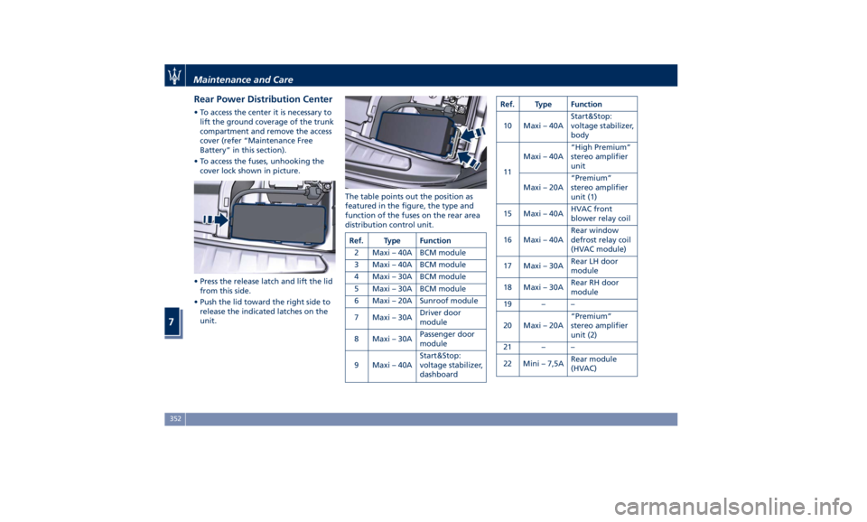
• To access the fuses, unhooking the
cover lock shown in picture.
• Press the release latch and lift the lid
from this side.
• Push the lid toward the right side to
release the indicated latches on the
unit. The table points out the position as
featured in the figure, the type and
function of the fuses on the rear area
distribution control unit.
Ref. Type Function
2 Maxi – 40A BCM module
3 Maxi – 40A BCM module
4 Maxi – 30A BCM module
5 Maxi – 30A BCM module
6 Maxi – 20A Sunroof module
7 Maxi – 30A Driver door
module
8 Maxi – 30A Passenger door
module
9 Maxi – 40A Start&Stop:
voltage stabilizer,
dashboard Ref. Type Function
10 Maxi – 40A Start&Stop:
voltage stabilizer,
body
11 Maxi – 40A “High Premium”
stereo amplifier
unit
Maxi – 20A “Premium”
stereo amplifier
unit (1)
15 Maxi – 40A HVAC front
blower relay coil
16 Maxi – 40A Rear window
defrost relay coil
(HVAC module)
17 Maxi – 30A Rear LH door
module
18 Maxi – 30A Rear RH door
module
19 – –
20 Maxi – 20A “Premium”
stereo amplifier
unit (2)
21 – –
22 Mini – 7,5A Rear module
(HVAC)Maintenance and Care
7
352
Page 359 of 396
Ref. Type Function
8 Mini – 10A Start & Stop
switch,
diagnostic outlet
Bulb Replacement The signal failure of an external light
(turn signal, low beam and high beam,
number plate light, reverse light and
brake light) is communicated to the
instrument cluster that displays on the
TFT screen in a graphical form and
with a text message which light is
faulty (see example in the figure).
Front Headlights The lights are arranged as follows:
1 Low-beam/high-beam LED.
2 Position and DRL light LED.
3 Direction indicator LED.
4 Side-marker light LED.
5 Side reflex-reflector.
6 Bending light LED.Maintenance and Care
7
355
Page 392 of 396

Seat Adjustment .............98
Service .....................10
Siri Smart Personal Assistant .... .215
Smoking Kit ................ .135
Snow Chains ............... .299
Spare parts service
Genuine Parts ..............13
Scheduled Maintenance .......13
Spare Parts Service .............13
SRS (Supplemental Restraint
System) ....................66
Start&Stop System ........... .220
Occupant Safety Function .... .222
Start&Stop Active Indicator . . . .155
Start&Stop Disable Indicator . . . .173
Start&Stop Failure Indicator
Light ................... .174
Start&Stop Function Disabling
Indicator ................ .222
Start&Stop Menu .......... .164
Start&Stop System Failure .... .224
Start the Engine
Engine Start Failure ......... .219
Engine Turn Off ........... .220
Steering Wheel
Heated Steering Wheel ...... .111
Phone and Voice Controls on
Steering Wheel ............ .213
Sunroof
Pinch Protect Feature ....... .142
Slide Opening Sunroof ....... .142
Sunroof Maintenance ....... .143
Venting Sunroof ........... .142 Sunshades ...................48
Power Sunshades ............50
Power Sunshades on Rear
Window ..................48
Power Sunshades on the Rear Doors
Windows ..................48
Sun Visors ................. .135
Surround View Camera System ....87
Symbols ....................14
Danger Symbols .............14
Symbols of Prohibitions and
Compulsory Measures .........14
Tables .................... .137
TCS (Traction Control System) .... .250
Technical Data .............. .375
Telltales
Telltales on Speedometer ..... .153
T
elltales on Tachometer ...... .155
Warning/Indicator Lights of Set
Modes/Functions on Display . . . .170
TFT Display: Menus and Settings . . .157
Tires
Change a Tire ............. .316
Compact spare tire ......... .300
Department of Transportation
Uniform Tire Quality Grades . . . .296
General Information ........ .292
Inflation Pressure .......... .381
Punctured Tire, use ......... .316
Replacement Tires .......... .298
Tire Pressure .............. .296
Tire Pressure Checkup ....... .297 Tire Safety Information ...... .292
TPMS - Tire Pressure Monitoring
System .................. .300
Winter Tires .............. .299
ToolKit................... .314
Towing
Towing a Disabled Vehicle .... .325
Towing the Vehicle ......... .325
Vehicle Towing Conditions .... .325
TPMS System ............... .300
Tire Pressure Low Warning .... .301
TPMS Deactivation ......... .303
Traffic Sign Assist - TSA ........ .290
Transmission, Automatic ....... .224
Automatic Transmission Lever . . .225
Automatic Transmission Range . .228
Malfunction and Overheating
Conditions ............... .232
Transmission Manual Release of P
(Park) Position ............ .322
Transmitter, Key fob RKE
Preventing Inadvertent Locking of
Key fob RKE Transmitter Inside the
Vehicle ...................43
Trunk
Power Trunk Lid/Hand Free
(optional) .................53
Trunk Safety ...............57
Trunk Lid
Power Trunk Lid Emergency
Release ...................56
Power Trunk Lid/Hand Free
(optional) .................53Index
9 388