2019 MASERATI QUATTROPORTE stop start
[x] Cancel search: stop startPage 244 of 396
corresponding button once: the yellow
LED on the button will turn on.
To reactivate the Start&Stop function,
press the same button again: the LED
will turn off.
Activate/Deactivate I.C.E., SPORT and
(Suspension) Drive Mode
To activate one of these drive mode,
press the corresponding button once:
the white LED on the button will turn
on.
To disable the drive mode activated,
press the same button again: the LED
will turn off. Monitoring Settings on Display
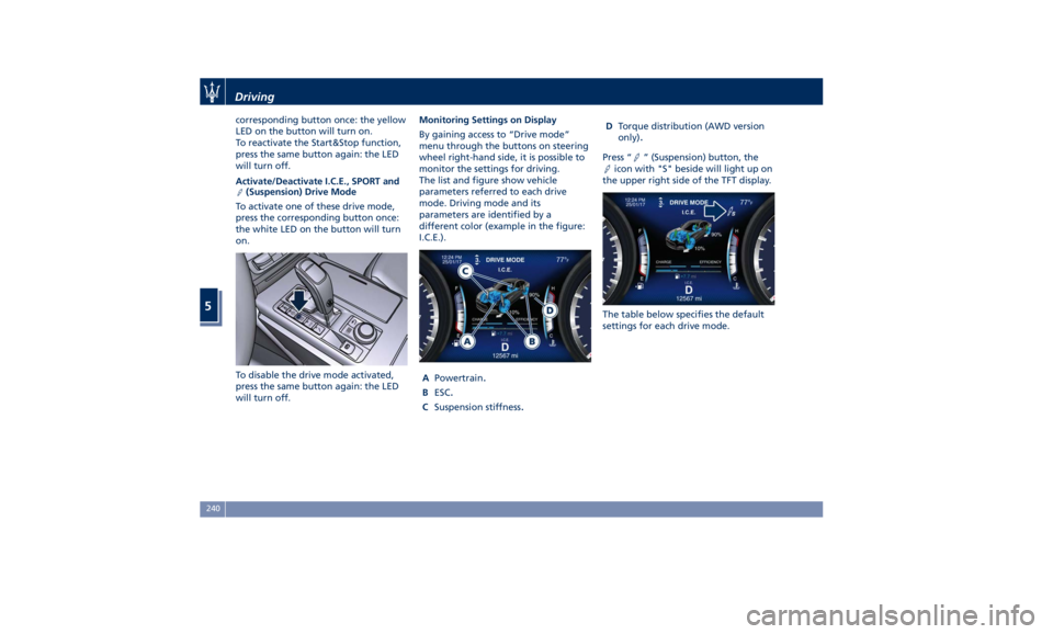
By gaining access to “Drive mode”
menu through the buttons on steering
wheel right-hand side, it is possible to
monitor the settings for driving.
The list and figure show vehicle
parameters referred to each drive
mode. Driving mode and its
parameters are identified by a
different color (example in the figure:
I.C.E.).
A Powertrain
. B ESC
. C Suspension stiffness
. D Torque distribution (AWD version
only)
. Press “ ” (Suspension) button, the
icon with "S" beside will light up on
the upper right side of the TFT display.
The table below specifies the default
settings for each drive mode.Driving
5
240
Page 253 of 396
deactivate the system see “Drive
Mode” in this section.
WARNING!
In SPORT mode the ESC control
thresholds are higher for maximum
performance on dry road surface. To
ensure maximum security of the ESC,
it is recommended not to activate
SPORT mode on surfaces with
medium- and low-grip (e.g., wet,
snow, dirt, etc..) with ESC system
active (
(ESC OFF) button not
pressed).
NOTE:
• When in “ESC off” mode, the TCS
functionality of ESC is deactivated
(except for the limited slip feature
described in the TCS paragraph of
this chapter). All other stability
features of ESC function regularly.
• To improve the vehicle's traction
when driving with snow chains, or
when starting off in deep snow,
sand, or gravel, it may be desirable
to switch to the “ESC off” mode by
pressing the
(ESC OFF) button and
remain in this operational mode no
longer than needed. Once the
situation requiring “ESC off” mode is overcome, turn the ESC on again by
pressing the
(ESC OFF) button.
This may also be performed while in
motion.
Anti-Lock Braking System (ABS)
and Electronic Brake-force
Distribution (EBD) The Anti-Lock Braking System (ABS)
provides increased vehicle stability and
brake performance under most
braking conditions. The system
automatically “pumps” the brakes
during severe braking to prevent
wheel lock-up.
The Electronic Brake-force Distribution
(EBD) prevents the rear wheels from
over-braking and provides greater
control of available braking forces
applied to the rear axle.
WARNING!
The ABS helps prevent the wheels
from locking, but it does not increase
the physical grip limits between the
tires and the road. Therefore, always
keep a safe distance from the vehicle
in front of yours and reduce your
speed when entering a curve. NOTE:
• When
the vehicle's speed is higher
than 7 mph (11 km/h), you may hear
a slight clicking sound as well as
other motor noises. The system is
performing a self-check cycle to
ensure that the ABS is working
properly.
• This self-check occurs each time the
vehicle is started and accelerated
past 7 mph (11 km/h).
ABS is activated during braking under
certain road or stopping conditions.
ABS-inducing conditions can include
ice, snow, gravel, bumps, railroad
tracks, loose debris.
You may also experience the following
when the brake system goes into Anti-
Lock:
• The ABS motor running (it may
continue to run for a short time
after the vehicle stops).
• The clicking sound of solenoid
valves.
• Brake pedal pulsations.
• A slight drop or fall away of the
brake pedal at the end of the stop.
These are all normal characteristics
of ABS functioning.Driving
5
249
Page 254 of 396
WARNING!
• The ABS contains sophisticated
electronic equipment that may be
susceptible to interference caused by
improperly installed or high output
radio transmitting equipment. This
interference can cause possible loss
of anti-lock braking capability.
Installation of such equipment
should be performed by qualified
Maserati personnel.
• Pumping the Anti-Lock Brakes will
diminish their effectiveness.
Pumping brakes makes the stopping
distance longer. Just press firmly on
your brake pedal when you need to
slow down or stop. Do not pump
brakes.
Traction Control System (TCS) The current device is an integral part
of the ESC system. It operates
automatically by reducing the power
transmitted by the engine in case of
slipping, loss of grip on wet floor
(aquaplaning), acceleration on slippery
snow-covered or frozen surfaces, etc.
Activating under slip conditions
different control systems: • if slippage affects both drive wheels,
it reduces the power transmitted by
the engine;
• if slippage only affects one drive
wheel, it brakes the slipping wheel
automatically.
Brake Assist System (BAS) This system completes the ABS system
by optimizing the vehicle braking
capacity during emergency brake
maneuvers. The system detects an
emergency braking situation by
sensing the rate and amount of brake
application and then applies optimum
pressure to the brakes in order to help
reduce braking distances.
The quick brake coupling is optimal for
BAS performances. In order to fully
exploit the system, apply continuous
brake pedal pressure during the entire
vehicle stop sequence. Do not reduce
brake pedal pressure earlier than
required. Once the brake pedal is
released, the BAS is deactivated.
Brake Throttle Override (BTO) To complete the range of systems that
assist braking, the vehicle is equipped
with BTO, which is designed to stop
the vehicle even when it is during
acceleration. If the brake pedal is
depressed together with the accelerator, the system does not
consider as “conflict” the sequence
“brake-first-then-accelerator” of pedal
application and it will not engage the
BTO. When the system recognizes that
the accelerator pedal is stuck pressed
and the sequence “accelerator-first-
then-brake-pressed” (this sequence is
recognized as a “conflict”), the engine
power should be automatically
reduced and, if the driver continues to
depress the accelerator and the brake
pedal, the system can make the vehicle
come to a complete stop.
Additionally, if the brake pedal is
released when the accelerator is still
stuck pressed, the corresponding
engine torque increases gradually to a
safe value.
During this event, the ETC light
indicator will illuminate. The system
exits from this strategy when the
accelerator pedal is completely
released.
Hill Start Assist (HSA) The HSA system is designed to assist
the driver when starting a vehicle
uphill. HSA will maintain the level of
brake pressure applied for a short
period of time also after releasing the
brake pedal.Driving
5
250
Page 255 of 396
If the driver does not apply the
throttle during this short period of
time, the system will release brake
pressure and the vehicle will start
sloping down. The system will release
brake pressure proportionally to the
amount of throttle/torque applied as
the vehicle starts to move in the
chosen direction.
HSA Activation Criteria
The following criteria must be met in
order for HSA to activate:
• vehicle is stationary;
• gear selection matches vehicle uphill
direction (i.e., vehicle facing uphill is
in forward gear; vehicle backing
uphill is in reverse gear).
HSA will work in R (Reverse) and all
forward gears when the activation
criteria have been met.
The system will not activate if the
transmission is placed in N (Neutral) or
P (Park). Using the Brakes CAUTION!
To obtain a good performance by
brake pads and discs, avoid sudden
braking during the first 190 mi
(300 km).
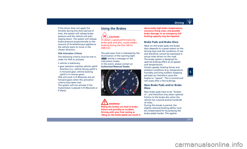
The pad wear limit is indicated by the
illumination
of the
warning light
and by a message on the
instrument cluster.
In this event, please contact an
Authorized Maserati Dealer .
WARNING!
Riding the brakes can lead to brake
failure and possibly an accident.
Driving with your foot resting or
riding on the brake pedal can result in abnormally high brake temperatures,
excessive lining wear, and possible
brake damage. In an emergency full
braking capacity may be impaired.
Brake Pads and Brake Discs Wear on the brake pads and brake
discs depends to a great extent on the
driving style and the conditions of use
and therefore cannot be expressed in
actual miles driven on the road.
The brake system is designed for
optimal braking effect at all speeds
and temperatures.
Certain speeds, braking forces and
ambient conditions (e.g. temperature,
humidity and long outdoor stopping
periods) can therefore cause the
brakes to “squeal”. This is normal and
will cease after a few brakings.
New Brake Pads and/or Brake
Discs New brake pads have to be “broken
in”, and therefore only attain optimal
friction to the brake disc when the
vehicle has covered several hundreds
of miles.
During this break-in period, the
slightly reduced braking ability must
be compensated for by pressing the
brake pedal harder. This appliesDriving
5
251
Page 256 of 396
whenever the brake pads and/or brake
discs are replaced.
Brake Overheating Driving on mountain roads with steep
slopes or a sports use of the vehicle
could overheat the brake system
components. In these conditions, the
parking brake must not be used since
the push of the power actuator might
not be sufficient to ensure vehicle
braking, especially on a slope.
Drive normally without braking to
allow the brakes to cool down a few
minutes before stopping. The
automatic or manual activation of the
parking brake will ensure vehicle
braking.
Brake overheating could also cause
“squeals” and “vibration”. Use of the Engine Breaking-In Today's most modern production
methods are designed to provide
extremely precise construction and
assembly of components. However,
moving parts do undergo a settling
process, basically in the first hours of
vehicle operation.
Do not drive keeping at a constant
high speed rate for a prolonged time.
While cruising, brief full-throttle
acceleration within the limits of local
traffic laws contributes to a good
break-in. Wide-open throttle
acceleration in low gear can be
detrimental and should be avoided.
The engine oil installed in the engine
at the factory is a high-quality energy
conserving type lubricant. Oil changes
should be consistent with anticipated
climate conditions under which vehicle
operations will occur. For the
recommended viscosity and quality
grades, see “Refillings” in section
“Features and Specifications”.
A new engine may consume some oil
during its first few thousand
miles/kilometers of operation. This
should be considered as a normal part of the break-in and not interpreted as
an indication of malfunction.
Specific Requirements
Avoid exceeding 5000 rpm for the first
620 mi trip (1000 km).
After starting the vehicle, do not
exceed 4000 rpm until the engine has
warmed up sufficiently (coolant
temperature: 149-158°F /65 70°).
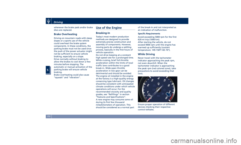
While Driving Never travel with the tachometer
indicator approaching the peak rpm,
not even downhill. When the
tachometer indicator is approaching
the peak rpm (red colored zone), take
precautions to avoid exceeding that
limit.
Ensure proper operation of different
devices checking their respective
control telltales.Driving
5
252
Page 268 of 396
NOTE:
The displayed warning is a warning for
the driver to take action and does not
necessarily mean that the Forward
Collision Warning (FCW) system is
applying the brakes autonomously.
Overtake Aid When driving with ACC engaged and
following a target vehicle, the system
will provide an additional acceleration
to assist in passing vehicles in front.
This additional acceleration is
triggered when the driver utilizes the
left turn signal to start overtaking. In
locations with left hand drive traffic,
overtake aid is active only when
passing on the left hand side of the
target vehicle.
When a vehicle goes from a location
with left hand drive traffic to a
location with right hand drive traffic,
the ACC system will automatically
detect traffic direction. In this
condition, overtake aid is active only
when passing on the right side of the
target vehicle. This additional
acceleration is triggered when the
driver utilizes the right turn signal to
start overtaking. In this condition the
ACC system will no longer provide
overtake aid on the left side until it determines that the vehicle has moved
back to a location with left hand drive.
ACC Operation Before and
During Stop If an ACC host vehicle follows a target
vehicle to a standstill, after two or
three seconds the system will not be
able to resume driving the car
autonomously. In this condition, TFT
displays an instruction message pop up
for 5 seconds.
When the ACC system brings the
vehicle to a standstill while following a
target vehicle, the brakes are released
after two-three seconds after the stop
and at the same time the system
inserts the parking brake. When
parking brake engages the ACC
deactivates going to ready state.
At this point the driver must reengage
the system acting on the multifunction
control (RES + or SET -) or alternatively
on the accelerator pedal. While ACC
with Stop is holding your vehicle at a
standstill, if the driver unbuckles the
seatbelt or opens the door, the ESC
system will activate the EPB. During
standstill, ACC system monitors the
occupant detection signals: if the
driver's seatbelt becomes unbuckled,
the ACC system shall be cancelled
when the EPB is applied. WARNING!
• When the ACC system is resumed,
the driver must ensure that there are
no pedestrians, vehicles or objects in
the path of the vehicle. Failure to
follow these warnings can result in a
collision and death or serious
personal injury.
• During the automatic stopping
behind a vehicle in some rare cases it
may happen that the system does
not recognize the rearmost point of
the vehicle ahead but a target under
the vehicle ahead (e.g. the back axis
of a truck with a high loading edge
or a bumper of a vehicle although
overhanging load is hanging over
the vehicle’s rear). In these cases the
system cannot guarantee the
appropriate stopping distance
leading to collision in the worst case.
For this reason the driver has to be
attentive and ready to brake during
automatic stops.Driving
5
264
Page 295 of 396
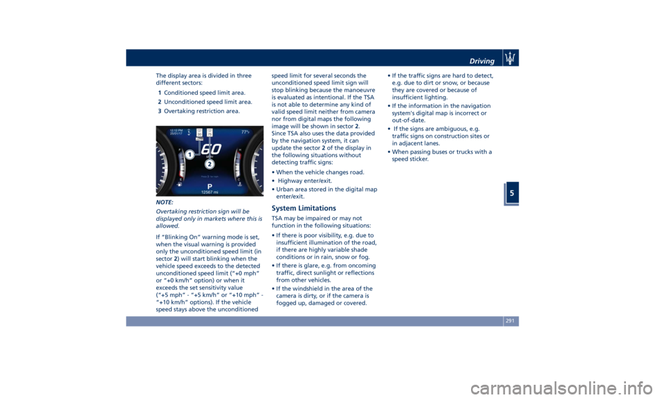
The display area is divided in three
different sectors:
1 Conditioned speed limit area.
2 Unconditioned speed limit area.
3 Overtaking restriction area.
NOTE:
Overtaking restriction sign will be
displayed only in markets where this is
allowed.
If “Blinking On” warning mode is set,
when the visual warning is provided
only the unconditioned speed limit (in
sector 2 ) will start blinking when the
vehicle speed exceeds to the detected
unconditioned speed limit (“+0 mph”
or “+0 km/h” option) or when it
exceeds the set sensitivity value
(“+5 mph” - “+5 km/h” or “+10 mph” -
“+10 km/h” options). If the vehicle
speed stays above the unconditioned speed limit for several seconds the
unconditioned speed limit sign will
stop blinking because the manoeuvre
is evaluated as intentional. If the TSA
is not able to determine any kind of
valid speed limit neither from camera
nor from digital maps the following
image will be shown in sector 2 .
Since TSA also uses the data provided
by the navigation system, it can
update the sector 2 of the display in
the following situations without
detecting traffic signs:
• When the vehicle changes road.
• Highway enter/exit.
• Urban area stored in the digital map
enter/exit.
System Limitations TSA may be impaired or may not
function in the following situations:
• If there is poor visibility, e.g. due to
insufficient illumination of the road,
if there are highly variable shade
conditions or in rain, snow or fog.
• If there is glare, e.g. from oncoming
traffic, direct sunlight or reflections
from other vehicles.
• If the windshield in the area of the
camera is dirty, or if the camera is
fogged up, damaged or covered. • If the traffic signs are hard to detect,
e.g. due to dirt or snow, or because
they are covered or because of
insufficient lighting.
• If the information in the navigation
system's digital map is incorrect or
out-of-date.
• If the signs are ambiguous, e.g.
traffic signs on construction sites or
in adjacent lanes.
• When passing buses or trucks with a
speed sticker.Driving
5
291
Page 319 of 396
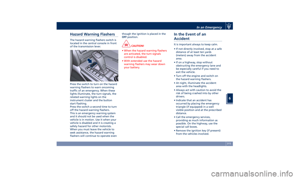
Hazard Warning Flashers The hazard warning flashers switch is
located in the central console in front
of the transmission lever.
Press the switch to turn on the hazard
warning flashers to warn oncoming
traffic of an emergency. When these
lights illuminate, the turn signals, the
related warning lights on the
instrument cluster and the button
start flashing.
Press the switch a second time to turn
off the hazard warning flashers.
This is an emergency warning system
and it should not be used when the
vehicle is in motion. Use it when your
vehicle is disabled and it is creating a
safety hazard for other motorists.
When you must leave the vehicle to
seek assistance, the hazard warning
flashers will continue to operate even though the ignition is placed in the
OFF position.
CAUTION!
• When the hazard warning flashers
are activated, the turn signals
control is disabled.
• With extended use the hazard
warning flashers may wear down
your battery.
In the Event of an
Accident It is important always to keep calm.
• If not directly involved, stop at a safe
distance of at least ten yards
(meters) away from the accident
area.
• If on a highway, stop without
obstructing the emergency lane and
be especially careful if you need to
exit the vehicle.
• Turn off the engine and switch on
the hazard warning flashers.
• At night, illuminate the accident
area with the headlights.
• Always act with caution to avoid the
risk of being crashed into by other
drivers.
• Indicate that an accident has
occurred by placing the emergency
triangle (if equipped) in a well
visible position and at the prescribed
distance.
• Call the emergency services,
providing as much information as
possible. On the highway, use the
special call boxes.
• Remove the ignition key (if present)
from the vehicles involved.In an Emergency
6
315