2019 MASERATI QUATTROPORTE width
[x] Cancel search: widthPage 89 of 396

or when the vehicle is overtaken by
motorcycles or other vehicles on one
or both sides in a queue of traffic.
When you set the volume, only the
parking sensor acoustic signal will be
affected. The radio or any other
devices connected to the vehicle
sound system will not be affected.
Refer to chapter “MTC+ Settings” in
section “Dashboard Instruments and
Controls” for further information.
Rear Parking Camera Your vehicle is equipped with a rear
parking camera that allows you to see
an image on the MTC+ screen of the
rear surroundings of your vehicle
whenever the shift lever is put into R
(Reverse).
When “Parkview Camera Off Delay”
mode is enabled, the rear view image
shall be displayed for up to 10 seconds
after shifting out of R (Reverse).
When “Rearwiew Camera Delay”
mode is enabled, the rear view image
shall be displayed for up to 10 seconds
after shifting out of R (Reverse).
To assist the driver during maneuvers
on dead-ends/roads and on
intersections, the vehicle may be
equipped with an optional surround
view camera system. In this case, the
rear parking camera is integrated into
the surround view camera system. In
both configurations (rear parking
camera only or surround view camera
system), you can always monitor the
rear view. For more details on this
option, see chapter "Surround View
Camera System (optional)" in this
section.
The image will be displayed along
with a caution note to “Check Entire
Surroundings” across the top of the screen. After five seconds this note
will disappear.
The rear parking camera is located on
the rear of the vehicle above the rear
license plate.
When the shift lever is shifted out of R
(Reverse), the rear camera mode is
exited and the navigation or audio
screen appears again.
When displayed, dynamic grid lines (if
the function is set to “MTC+ Settings”)
will illustrate the width of the vehicle
to assist with parking or aligning to a
hitch/receiver. The dynamic grid lines
will show separate zones in different
color that will help indicate the
distance to the rear of the vehicle.Before Starting
2
85
Page 277 of 396

System Availability The ADAS systems (LKA, CC, ACC, FCW
and HAS) help the driver while
driving. These systems can be set and
monitored simultaneously on the
display, after opening “Driver Assist”
menu (see paragraph “TFT Display:
Menus and Settings” under
“Instrument Cluster” in section
“Dashboard Instruments and
Controls”).
LKA is designed for an attentive
driver; therefore the system is
available only when his/her hands are
on the steering wheel or with hands
off for only a limited amount of time.
When the system is enabled it will
trigger cluster warning in case at least
one hand is not detected on the
steering wheel.
The torque application as well as the
vibration are suppressed/inhibited in
case of: high driver torque in the
steering wheel, high lateral
acceleration, hands not on the
steering wheel detected for more than
a certain time.
High dynamic driving behaviors,
driving on the lane boundary, or
driving off course will prevent the
function from working. FCW braking
and stability system interventions (ESC, ABS) will also prevent the system from
operating. Changing lanes results in
system inhibition for a certain time. In
addition, the driver must respect some
road characteristics such as
minimum-maximum width, lanes
clearly defined by two lane
boundaries and, only in limited cases
and for a limited time, at least one
lane boundary.
NOTE:
• In case of wet road or raining
conditions the function could be
disabled by the system in order to
minimize the risks.
• With lane boundaries it is mainly
referred to painted lines,
nevertheless the system in good
conditions might properly recognize
as valid lane boundaries also other
types (for example road edges,
curbs, etc..).
Being this function used to prevent
unintentional lane change/lane drift,
it will be temporary suppressed/
inhibited by a turn indicator
activation, therefore, graphic warning,
steering torque application and
vibration will be terminated. In this
condition in case of a vehicle detected
by the Blind Spot Assist (BSA) system in the covered area on the proper
side, there can be the transition from
LKA to Active Blind Spot Assist (ABSA)
(if this latter is on and properly
configured).
Function Description and
Operating Mode The intent of the function is to
prevent the lane departure by
warning the driver through indication
on the cluster and, if set, applying
steering torque and vibration.
Whenever the system is enabled there
will be graphic on the dedicated
screen in the driver assist page and for
the others it will be available in the
left top corner of the cluster screen.
The graphic which intent is to
represent at the glance the system
knowledge of the lane in front of the
car, the system suppression status and
warning.
For this reason, a simple colour code
has been adopted for each line (of the
two presented):
• Both grey lines means system is
enabled, not able to operate
(suppression condition present or
lane detection system not able to
properly estimate the lane);Driving
5
273
Page 286 of 396

Highly dynamic behaviours, driving on
the lane boundary, off course will
prevent the function from working.
FCW braking and stability system
interventions (ESC, ABS) will also
prevent the system from operating.
Changing lane results in system
inhibition for a certain time.
In addition the road must respect some
characteristics such as minimum-
maximum width, lane clearly defined
by two lane boundaries and only in
limited case for a limited time at least
one.
NOTE:
• In case of wet road or raining
conditions the function could be
disabled by the system in order to
minimize the risks.
• With lane boundaries it is mainly
referred to painted lines,
nevertheless the system in good
conditions might properly recognise
as valid lane boundaries also other
types (for example road edges, curbs,
etc..). Speed Range of Use Speed mph (km/h)
Minimum 37 (60)
Engaged/activated 37 (60)
Maximum 112 (180)
System Limitation Because of physical limits the system to
properly operate needs good visibility
(it might not work or not properly
operate in case of heavy rain, snow,
wet roads, fog, direct sun on the
camera, dirty windshield, low
illumination etc.)
Sharp turns, slopes and change in
slopes, poor lane boundaries, as well
as construction areas and all the
scenarios described in this paragraph
may challenge the system, therefore
be always ready to prevent any
unexpected behaviour of the car.
Damaged front bumper, windshield
replaced without proper technical
intervention may also lead to system
malfunction or system unavailability.
Other conditions such as faults, but
not explicitly indicated here may also
prevent/interrupt the system
intervention. ABSA Setting ABSA is configurable by the customer
in order to maximize its efficiency
based on the driver driving style and
his/her expectation of the system,
reducing at the same time the possible
invasiveness.
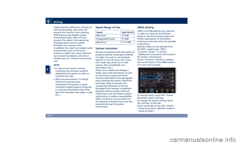
Setting modes can be selected from
the MTC+ System (see "MTC+
"Controls" Screen" in section
"Dashboard Instruments and Controls"
for further information).
Touch "Controls" soft-key to display
the current status of the ABSA system,
if it was in the on state.
To change status, touch the "Active
Blind Spot Assist" soft-key.
To change the system setting, touch
the soft-key on the side.
Driver warnings can be only "Visual",
"Visual & Acoustic" (default mode) or
"Visual & Haptic".Driving
5
282
Page 290 of 396

• Vehicle speed must be between 0 to
90 mph (0 and 145 km/h).
• No faults in the forward facing
camera, radar, EPS, or MTC+.
• Lane width between 3 to 4.6 yd (2.8
and 4.2 m).
• Turn signal not activated.
• No faults related to this system.
Speed Range of Use Speed mph (km/h)
Minimum 0 (0)
Engaged/activated
(with ACC engaged) 0 (0)
Engaged/activated
(with ACC not
engaged) 18 (30)
Maximum 90 (145)
• If set above the maximum speed,
HAS will not function after the
vehicle speed will reach the
maximum speed.
• If set below the maximum speed and
the ACC target speed is increased,
HAS will function up to the
maximum speed and then the system
will turn off automatically.
• When the ACC target speed is reduce
and speed is lower than the maximum speed, the system will start
automatically.
• If the ACC target speed is set under
the maximum speed, HAS is active
and vehicle speed increases above
the maximum speed due to slope,
HAS will continue to function.
HAS Monitoring on Instrument
Cluster HAS and the other ADAS systems
conditions can be monitored on
instrument cluster display by accessing
the “Driver Assist” page with the
buttons on the steering wheel (see
“Instrument Cluster” in section
“Dashboard Instruments and
Controls”).
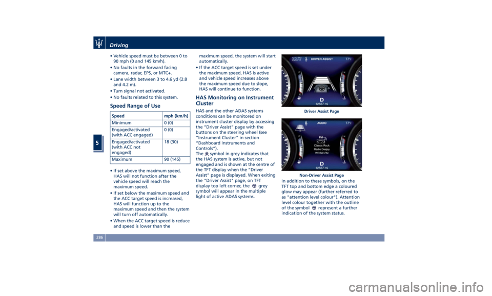
The
symbol in grey indicates that
the HAS system is active, but not
engaged and is shown at the centre of
the TFT display when the “Driver
Assist” page is displayed. When exiting
the "Driver Assist" page, on TFT
display top left corner, the
grey
symbol will appear in the multiple
light of active ADAS systems. In addition to these symbols, on the
TFT top and bottom edge a coloured
glow may appear (further referred to
as "attention level colour"). Attention
level colour together with the outline
of the symbol
represent a further
indication of the system status. Driver Assist Page
Non-Driver Assist PageDriving
5
286
Page 296 of 396

Tires - General Information Tire Safety Information Tire Markings
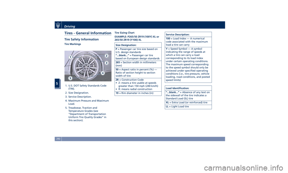
1. U.S. DOT Safety Standards Code
(TIN).
2. Size Designation.
3. Service Description.
4. Maximum Pressure and Maximum
Load.
5. Treadwear, Traction and
Temperature Grades (see
“Department of Transportation
Uniform Tire Quality Grades” in
this section). Tire Sizing Chart
EXAMPLE: P265/50 ZR19 (100Y) XL or
265/50 ZR19 (Y100) XL
Size Designation:
P = Passenger car tire size based on
U.S. design standards
“...blank...” = Passenger car tire
based on European design standards
265 = Section width in millimeters
(mm)
50 = Aspect ratio in percent (%) —
Ratio of section height to section
width of tire
ZR = Construction Code
• Z: means a tire usable at speeds
greater than 150 mph (240 km/h)
• R: means radial construction
19 = Rim diameter in inches (in) Service Description:
100 = Load Index — A numerical
code associated with the maximum
load a tire can carry
Y = Speed Symbol — A symbol
indicating the range of speeds at
which a tire can carry a load
corresponding to its load index
under certain operating conditions.
The maximum speed corresponding
to the speed symbol should only be
achieved under specified operating
conditions (i.e., tire pressure, vehicle
loading, road conditions, and posted
speed limits)
Load Identification:
“...blank...” = Absence of any text on
the sidewall of the tire indicates a
Standard Load (SL) tire
XL = Extra Load (or reinforced) tire
LL = Light Load tireDriving
5
292
Page 384 of 396

Dimensions Wheel base 124.84 in (3171 mm)
Total length 207.32 in (5266 mm)
Width without mirrors 76.69 in (1948 mm)
Width with mirrors 82.63 in (2099 mm)
Front track (*) 64.13 ÷ 64.25 in (1629 ÷ 1632 mm)
Rear track (*) 64.29 ÷ 64.88 in (1633 ÷ 1648 mm)
Front overhang 38.30 in (973 mm)
Rear overhang 44.17 in (1122 mm)
Height (*) 57.87 ÷ 58.42 in (1470 ÷ 1484 mm)
Boot compartment volume 18.7 cu. ft. (530 l)
(*) Variable size according to the motorization, the tire size and the optional installed.Features and Specifications
8
380