2019 MASERATI LEVANTE trunk
[x] Cancel search: trunkPage 265 of 436
In this ride height position driver can
set the “NORMAL” and “I.C.E. drive
modes. After the engine is switched
off, the drive mode is set to
“NORMAL”. If “OFF ROAD” drive
mode was set, “NORMAL” mode will
be set, but the user-set ride height
will remain until the speed threshold
is reached.
• Off Road 1 : raises the vehicle by
approx. 1 in (25 mm).
This is the height suitable for most
off road driving conditions until the
other off road option is needed. This
ride height can set only in “OFF
ROAD” drive mode. Select this
height while the vehicle speed is
below 50 mph (80 km/h). When in
the “Off Road 1” height, if the
vehicle speed remains between
80 km/h (50 mph) and 56 mph
(90 km/h) for over 30 seconds or if
vehicle speed exceeds 56 mph
(90 km/h), the vehicle will be
automatically lowered to
“NORMAL” height. For further
details, refer to "Off-road Drive" in
this section.
• Off Road 2 : raises the vehicle by
approx. 1.5 in (40 mm).
This height is intended for off-road
use only where maximum ground
clearance is required. This ride height can be set only in “OFF
ROAD” drive mode.
Select this height while the vehicle
speed is below 18 mph (30 km/h).
When in the “Off Road 2” height, if
the vehicle speed remains between
18 mph (30 km/h) and 25 mph (40
km/h) for over 30 seconds or if
vehicle speed exceeds 25 mph
(40 km/h), the vehicle will be
automatically lowered to “Off Road
1” height. For further details, refer
to "Off-road drive" in this section.
• Aero 1 : lowers the vehicle by approx.
0.8 in (20 mm).
This height provides improved
aerodynamics by lowering the
vehicle. This ride height is available
in “NORMAL”, “SPORT ”, “
(Suspension)“ or “I.C.E.” drive
mode. System automatically lowers
the vehicle when speed remains
between 74 mph (120 km/h) and
80 mph (130 km/h) for over 15
seconds or if the vehicle speed
exceeds 80 mph (130 km/h). The
system will return to “NORMAL”
height when the vehicle speed
remains between 62 mph (100 km/h)
and 56 mph (90 km/h) for over 15
seconds or if the vehicle speed falls
below 56 mph (90 km/h). The vehicle
will enter “Aero 1” height, regardless of vehicle speed if the
“SPORT” mode is set.
• Aero 2 : lowers the vehicle by approx.
1.4 in (35 mm).
It is the height ensuring excellent
aerodynamics for top performance
by further lowering the vehicle. This
ride height is available in
“NORMAL”, “SPORT ”, “
(Suspension)“ or “I.C.E.” drive
mode.
This is the default ride height when
“CORSA” drive mode (TROFEO
version only) is set. System
automatically lowers the vehicle
when speed exceeds 105 mph
(170 km/h) or when it remains
between 105 mph (170 km/h) and
115 mph (185 km/h) for over 15
seconds. The system will return to
Aero 1 height when the vehicle
speed remains between 96 mph
(155 km/h) and 87 mph (140 km/h)
for over 15 seconds or if the vehicle
speed falls below 87 mph (140 km/h).
• Easy/Entry : lowers the vehicle by
approx. 1.8 in (45 mm).
This mode lowers the vehicle for
easier passenger entry and exit as
well as lowering the rear of the
vehicle for easier loading and
unloading of cargo from the trunk.
This ride height can be set only inDriving
5
261
Page 341 of 436
• Insert the fuel nozzle fully into the
filler.
WARNING!
• To avoid the risk of fire, do not
approach the filler with open flames
or cigarettes!
• To avoid the risk of inhaling noxious
fumes, do not breathe close to the
fuel filler door, when opened.
• Never have any smoking materials
lit in or near the vehicle when the
fuel filler door is open or the tank is
being filled.
• Never add fuel when the engine is
running. This violates most
fire-prevention regulations and may
cause the Malfunction Indicator
Light
to turn on (see
“Instrument Cluster” in section
“Dashboard Instruments and
Controls”).
• Fill the vehicle with fuel. Fuel tank
capacity
is indicated in the
“Refillings” table in section
“Features and Specifications”.
When the fuel nozzle “clicks” or
shuts off, the fuel tank is basically
full: it is possible to further ensure
refueling by enabling the fuel nozzle additional fuel supply until two
clicks. After the two additional clicks,
the amount of fuel allowed by the
system is very low, we recommend
therefore not to persist further.
• Wait approximately 10 seconds
before removing the fuel nozzle in
order to ensure completed supply of
residual fuel and restrict the risk of
fouling the fuel filler door area.
• Remove the fuel nozzle.
• Insert the cap on the fuel filler neck.
• Tighten the cap, turning it clockwise
until it stops.
• Close the fuel filler door.
CAUTION!
To avoid fuel spillage and overfilling,
do not “top off” the fuel tank after
filling.
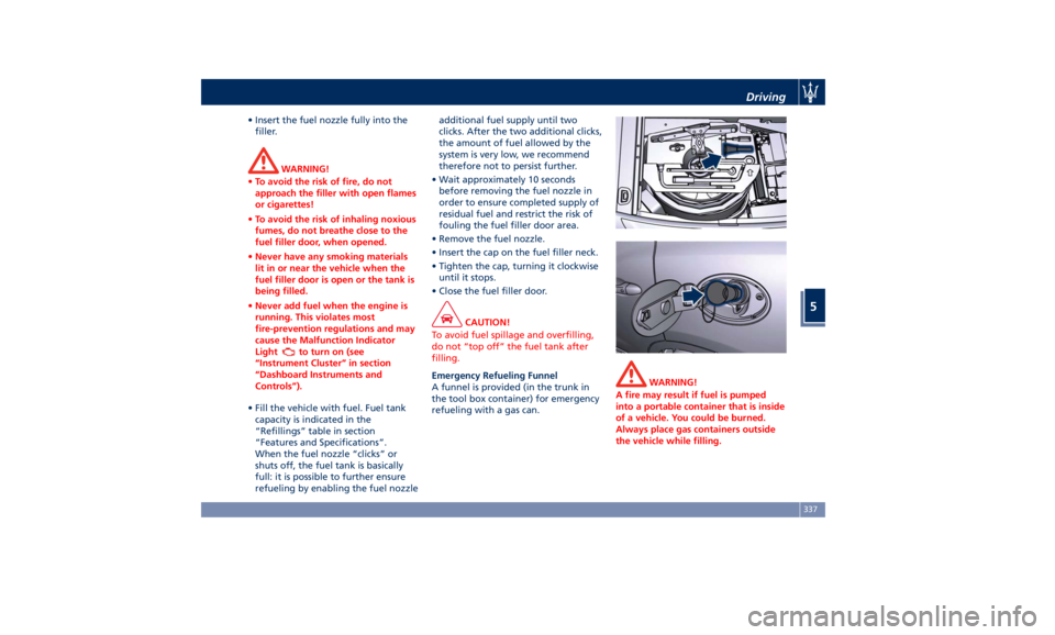
Emergency Refueling Funnel
A
funnel is provided (in the trunk in
the tool box container) for emergency
refueling with a gas can. WARNING!
A fire may result if fuel is pumped
into a portable container that is inside
of a vehicle. You could be burned.
Always place gas containers outside
the vehicle while filling.Driving
5
337
Page 342 of 436
Fuel Filler Cap Open Warning
Light After refueling the car
performs a check of the fuel
filler cap and the amber
warning light on the TFT
display comes on if it is not correctly
closed, after approximately 10 minutes
also depending on driving conditions.
If the problem is in the fuel system, the
Malfunction Indicator Light
also
comes on.
If the fuel filler cap is locked and the
issue remains in the system, at the next
engine start only the Malfunction
Indicator Light
comes on. In this
case, contact an Authorized Maserati
Dealer .
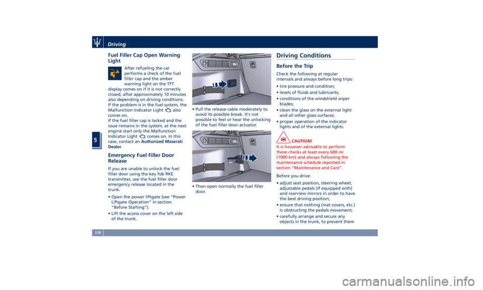
Emergency Fuel Filler Door
Release If you are unable to unlock the fuel
filler door using the key fob RKE
transmitter, use the fuel filler door
emergency release located in the
trunk.
• Open the power liftgate (see “Power
Liftgate Operation” in section
“Before Starting”).
• Lift the access cover on the left side
of the trunk. • Pull the release cable moderately to
avoid its possible break. It's not
possible to feel or hear the unlocking
of the fuel filler door actuator.
• Then open normally the fuel filler
door.Driving Conditions Before the Trip Check the following at regular
intervals and always before long trips:
• tire pressure and condition;
• levels of fluids and lubricants;
• conditions of the windshield wiper
blades;
• clean the glass on the external light
and all other glass surfaces;
• proper operation of the indicator
lights and of the external lights.
CAUTION!
It is however advisable to perform
these checks at least every 600 mi
(1000 km) and always following the
maintenance schedule reported in
section “Maintenance and Care”.
Before you drive:
•
adjust seat position, steering wheel,
adjustable pedals (if equipped with)
and rearview mirrors in order to have
the best driving position;
• ensure that nothing (mat covers, etc.)
is obstructing the pedals movement;
• carefully arrange and secure any
objects in the trunk, to prevent themDriving
5
338
Page 347 of 436
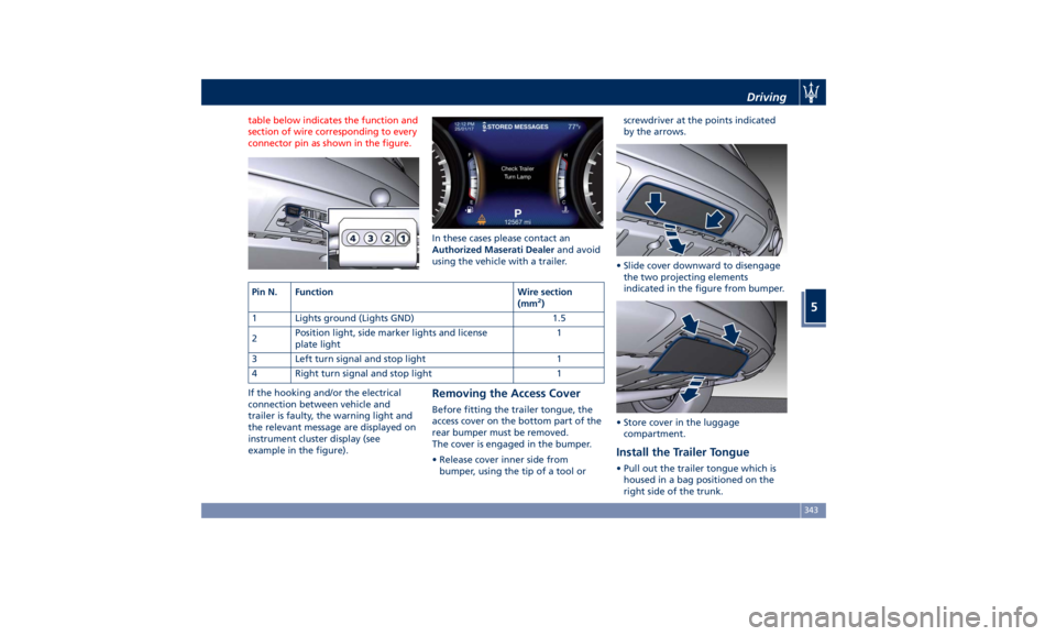
table below indicates the function and
section of wire corresponding to every
connector pin as shown in the figure.
If the hooking and/or the electrical
connection between vehicle and
trailer is faulty, the warning light and
the relevant message are displayed on
instrument cluster display (see
example in the figure). In these cases please contact an
Authorized Maserati Dealer and avoid
using the vehicle with a trailer.
Removing the Access Cover Before fitting the trailer tongue, the
access cover on the bottom part of the
rear bumper must be removed.
The cover is engaged in the bumper.
• Release cover inner side from
bumper, using the tip of a tool or screwdriver at the points indicated
by the arrows.
• Slide cover downward to disengage
the two projecting elements
indicated in the figure from bumper.
• Store cover in the luggage
compartment.
Install the Trailer Tongue • Pull out the trailer tongue which is
housed in a bag positioned on the
right side of the trunk.Pin N. Function Wire section
(mm 2
)
1 Lights ground (Lights GND) 1.5
2 Position light, side marker lights and license
plate light 1
3 Left turn signal and stop light 1
4 Right turn signal and stop light 1 Driving
5
343
Page 348 of 436
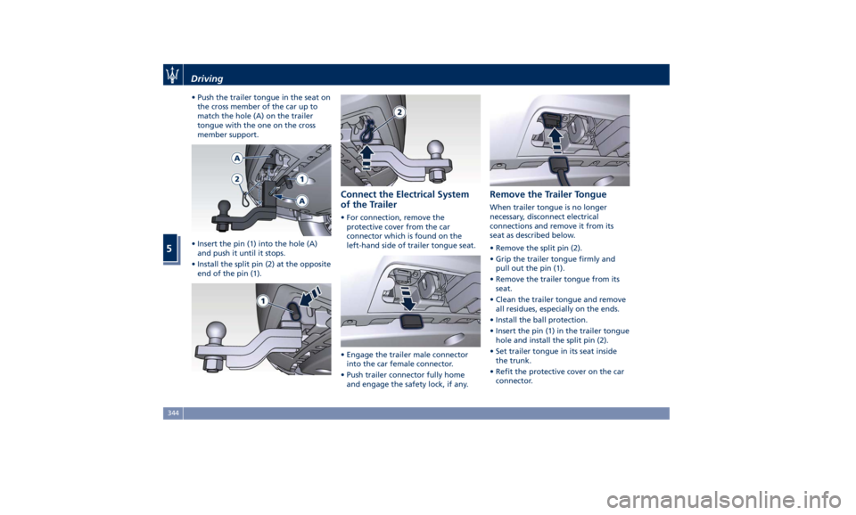
• Push the trailer tongue in the seat on
the cross member of the car up to
match the hole (A) on the trailer
tongue with the one on the cross
member support.
• Insert the pin (1) into the hole (A)
and push it until it stops.
• Install the split pin (2) at the opposite
end of the pin (1). Connect the Electrical System
of the Trailer • For connection, remove the
protective cover from the car
connector which is found on the
left-hand side of trailer tongue seat.
• Engage the trailer male connector
into the car female connector.
• Push trailer connector fully home
and engage the safety lock, if any. Remove the Trailer Tongue When trailer tongue is no longer
necessary, disconnect electrical
connections and remove it from its
seat as described below.
• Remove the split pin (2).
• Grip the trailer tongue firmly and
pull out the pin (1).
• Remove the trailer tongue from its
seat.
• Clean the trailer tongue and remove
all residues, especially on the ends.
• Install the ball protection.
• Insert the pin (1) in the trailer tongue
hole and install the split pin (2).
• Set trailer tongue in its seat inside
the trunk.
• Refit the protective cover on the car
connector.Driving
5
344
Page 352 of 436
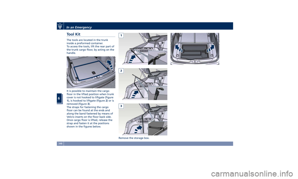
Tool Kit The tools are located in the trunk
inside a preformed container.
To access the tools, lift the rear part of
the trunk cargo floor, by acting on the
handle.
It is possible to maintain the cargo
floor in the lifted position when trunk
cover is not hooked to liftgate (figure
1 ), is hooked to liftgate (figure 2 )oris
removed (figure 3 ).
The straps for fastening the cargo
floor can be found at the ends and
along the band fastened by means of
Velcro inserts on the floor back side.
Once cargo floor is lifted, release the
strap and fasten it at the positions
shown in the figures below.
Remove the storage box.In an Emergency
6
348
Page 353 of 436
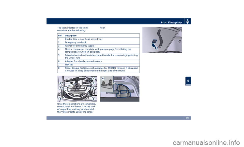
The tools inserted in the trunk
container are the following:
Once these operations are completed,
stretch band and fasten it at the back
of cargo floor, making sure to match
the Velcro inserts. Lower the cargo floor.
Ref. Description
1 Double torx + cross-head screwdriver
2 Emergency tow hook
3 Funnel for emergency supply
4 Electric compressor complete with pressure gage for inflating the
compact spare wheel (if equipped)
5 Extended wrench with rubber-coated handle for unscrewing/tightening
the wheel nuts
6 Adapter for wheel extended wrench
7 Jack set
8 Trailer tongue (optional, not available for TROFEO version). If equipped,
is housed in a bag positioned on the right side of the trunk. In an Emergency
6
349
Page 356 of 436
(Continued)
go back to normal operation.
NOTE:
The compact spare wheel is supplied in
aluminum or steel: the pictures show
the one in aluminum.
The compact spare wheel is stored in
the trunk and is supplied deflated in
order to limit the amount of space
occupied. An electric compressor is also
provided for inflating. In the event of
a tire puncture, proceed as follows.
• Stop the vehicle in a place that does
not constitute a danger to traffic and
where the wheel can be changed
safely. The vehicle must be level and
on firm ground.
• Select the P (Park) mode and then
engage manually the electric parking
brake and move the ignition switch
to OFF position.
• If necessary, turn the hazard warning
flashers on and place the warning
triangle (if equipped) at the required
distance.
WARNING!
• The jack should be used on level firm
ground wherever possible. • It is recommended that the wheels
of the vehicle be chocked, and that
no person should remain in a vehicle
that is being jacked.
• If the vehicle has been stopped on a
slope or an uneven surface, place
chocks or other suitable items in
front of or behind the wheels to
stop the vehicle from moving.
• Never start or run the engine with
the vehicle on a jack.
• No person should place any portion
of their body under a vehicle that is
supported by a jack.
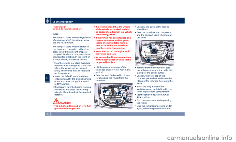
• Lift the ground coverage of the
trunk
(see chapter “T ool Kit” in this
section).
• Take the tools (indicated in picture)
for changing the wheel from the
container. • Unscrew and pull out the locking
wheel knob.
• Take the container, the compressor
and the compact spare wheel out of
the trunk.
• Remove from the compressor case
the inflation hose and the cable with
a plug for the power outlet.
• Unscrew the valve cap of the
compact spare wheel and screw the
fitting of the inflation hose onto the
valve.
• Insert the plug in one of the
available power outlets fitted in the
trunk or passenger compartment.
• Set the ignition device on ACC or
RUN position.
• Turn the compressor on by pressing
the switch.
• Stop the compressor pressing switch
again, when the pressure indicatedIn an Emergency
6
352