2019 MASERATI LEVANTE trunk
[x] Cancel search: trunkPage 359 of 436
will be compromised. Avoid
accelerating to full speed, heavy
braking and fast cornering.
• The compact spare wheel must be
inflated to the recommended tire
pressure (see “Tire Inflation
Pressure” in section “Features and
Specifications”).
• For safety reasons, it is absolutely
forbidden to drive with more than
one compact spare wheel fitted on
the vehicle.
• Snow chains cannot be fitted on the
compact spare wheel.
• The spare wheel can travel a
maximum of 1,800 mi (3.000 km).
To Refit the Standard Wheel with
Repair
ed or Replaced Tire
• Following the procedure and the
caution described above, raise the
vehicle and remove the compact
spare wheel reusing the supplied
wrench with adapter, suitably
extended.
• Fit the standard wheel with repaired
or replaced tire.
• Tighten the original bolts on the
wheel.
• Lower the vehicle and remove the
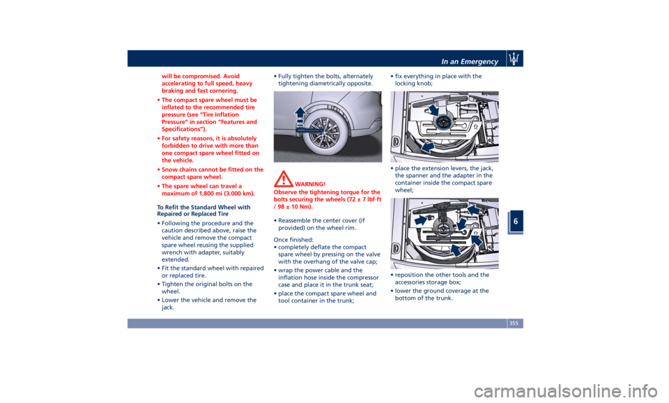
jack. • Fully tighten the bolts, alternately
tightening diametrically opposite.
WARNING!
Observe the tightening torque for the
bolts securing the wheels (72 ± 7 lbf·ft
/ 98 ± 10 Nm).
• Reassemble the center cover (if
provided)
on the wheel
rim.
Once finished:
• completely deflate the compact
spare wheel by pressing on the valve
with the overhang of the valve cap;
• wrap the power cable and the
inflation hose inside the compressor
case and place it in the trunk seat;
• place the compact spare wheel and
tool container in the trunk; • fix everything in place with the
locking knob;
• place the extension levers, the jack,
the spanner and the adapter in the
container inside the compact spare
wheel;
• reposition the other tools and the
accessories storage box;
• lower the ground coverage at the
bottom of the trunk.In an Emergency
6
355
Page 362 of 436
(Continued)
• Do not attempt jump-starting if the
discharged battery is frozen.
• To avoid the risk of explosion or fire,
do not approach the battery with
open flames or cigarettes that could
generate sparks.
NOTE:
If you need to disconnect the battery
from the vehicle electrical system, see
“Maintenance — Free Battery” in
section “Maintenance and Care”).
WARNING!
California Proposition 65
Operating, servicing and maintaining
a passenger vehicle or off-road vehicle
can expose you to chemicals including
such as, engine exhaust, carbon
monoxide, phthalates and lead, that
which are known to the State of
California to cause cancer and birth
defects or other reproductive harm. To
minimize exposure, avoid breathing
exhaust, do not idle the engine except
as necessary, service your vehicle in a
well-ventilated area and wear gloves
or wash your hands frequently when
servicing your vehicle. For more
information go to: www.P65Warnings.ca.gov/passenger-
vehicle
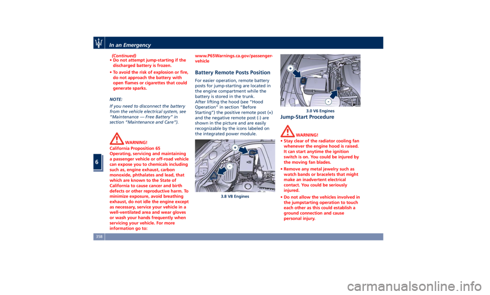
Battery Remote Posts Position For easier operation, remote battery
posts for jump-starting are located in
the engine compartment while the
battery is stored in the trunk.
After lifting the hood (see “Hood
Operation” in section “Before
Starting”) the positive remote post (+)
and the negative remote post (-) are
shown in the picture and are easily
recognizable by the icons labeled on
the integrated power module.
Jump-Start Procedure WARNING!
• Stay clear of the radiator cooling fan
whenever the engine hood is raised.
It can start anytime the ignition
switch is on. You could be injured by
the moving fan blades.
• Remove any metal jewelry such as
watch bands or bracelets that might
make an inadvertent electrical
contact. You could be seriously
injured.
• Do not allow the vehicles involved in
the jumpstarting operation to touch
each other as this could establish a
ground connection and cause
personal injury.3.8 V8 Engines 3.0 V6 EnginesIn an Emergency
6
358
Page 372 of 436

(Continued)
defects or other reproductive harm. To
minimize exposure, avoid breathing
exhaust, do not idle the engine except
as necessary, service your vehicle in a
well-ventilated area and wear gloves
or wash your hands frequently when
servicing your vehicle. For more
information go to:
www.P65Warnings.ca.gov/passenger-
vehicle
Heavy-Duty Vehicle Use If the car is mainly used under one of
the following conditions:
• towing a trailer;
• off-road;
• short, repeated journeys (less than
4–5 mi/7-8 km) at sub-zero outside
temperatures;
• engine often idling or driving long
distances at low speeds or long
periods of idleness;
you should perform the following
inspections more frequently than
recommended on the “Scheduled
Service Plan”:
• check front disc brake pad conditions
and wear; • check cleanliness of hood and trunk
locks, cleanliness and lubrication of
linkage;
• visually inspect conditions of: engine,
transmission, pipes and hoses
(exhaust - fuel system - brakes) and
rubber elements (boots - sleeves -
bushes - etc.);
• check battery charge;
• visually inspect condition of the
accessory drive belts;
• check and, if necessary, change
engine oil and replace oil filter;
• check and, if necessary, replace
pollen filter of the A/C system;
• check and, if necessary, replace air
cleaner filter.
CAUTION!
All maintenance operations for the
vehicle must be carried out by an
Authorized Maserati Dealer . For
routine and minor maintenance
operations which you can carry out
yourself, make sure that you have the
necessary experience and always use
suitable equipment, original Maserati
spare parts and the prescribed fluids.
Shall this not be the case, do not carry
any operation on your own and
contact an Authorized Maserati Dealer .
On Board Diagnostic System Your vehicle is equipped with a
sophisticated on board diagnostic
system called OBD II. This system
monitors the performance of the
emissions, engine, and automatic
transmission control systems. When
these systems are operating properly,
your vehicle will provide excellent
performance and fuel economy, as
well as engine emissions suited to
current government regulations.
If any of these systems require service,
the OBD II system will turn on the
Malfunction Indicator Light
on the
instrument cluster display (refer to
“Instrument Cluster” in section
“Dashboard Instruments and
Controls”). The system stores as well
diagnostic codes and other
information to assist your service
technician by performing repairs.
Although the vehicle will be driveable
and will not need towing, contact an
Authorized Maserati Dealer for service
as soon as possible.Maintenance and Care
7
368
Page 386 of 436
(Continued)
same type (vented).
NOTE:
Remote battery terminals for starting
are located in the engine
compartment for jump-starting to be
used with an auxiliary battery or a
battery from another vehicle (see
“Auxiliary Jump-Start Procedure”
chapter in section “In an Emergency”).
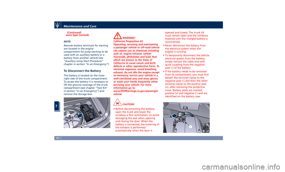
To Disconnect the Battery The battery is located on the inner
right side of the trunk compartment.
To access the battery it is necessary to
lift the ground coverage of the trunk
compartment (see chapter “Tool Kit”
in section “In an Emergency”) and
remove the storage box. WARNING!
California Proposition 65
Operating, servicing and maintaining
a passenger vehicle or off-road vehicle
can expose you to chemicals including
such as, engine exhaust, carbon
monoxide, phthalates and lead, that
which are known to the State of
California to cause cancer and birth
defects or other reproductive harm. To
minimize exposure, avoid breathing
exhaust, do not idle the engine except
as necessary, service your vehicle in a
well-ventilated area and wear gloves
or wash your hands frequently when
servicing your vehicle. For more
information go to:
www.P65Warnings.ca.gov/passenger-
vehicle
CAUTION!
• Before disconnecting the battery,
open the trunk and lower the
windows a few centimeters, to avoid
damaging the seal when opening
and closing the door. When the
battery is connected, the lowering of
the window is performed
automatically when the door is opened and closed. The trunk lid
must remain open and the windows
lowered until the charged battery is
reconnected.
• Never disconnect the battery from
the electrical system when the
engine is running.
• To temporarily disconnect the vehicle
electrical system from the battery,
simply remove the cable end with
quick coupling from the negative
post (-) of the battery.
• If the battery needs to be removed
from its compartment, you must first
detach the terminal clamp to the
negative post (-) and then the other
terminal clamp to the positive post
(+), after removing the protective
cover. Battery posts are marked
positive (+) and negative (-) and are
identified on the battery case.Maintenance and Care
7
382
Page 387 of 436
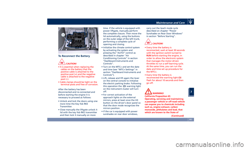
To Reconnect the Battery CAUTION!
• It is essential when replacing the
cables on the battery that the
positive cable is attached to the
positive post (+) and the negative
cable is attached to the negative
post (–).
• Cable clamps should be tight on the
terminal posts and free of corrosion.
After the battery has been
disconnected
and re-connected and
before starting the engine it is
necessary to proceed as follows:
• Unlock and lock the doors using one
more time the Key fob RKE
Transmitter.
• Close manually the liftgate unlock it
lid with the key fob RKE transmitter
and then lock it manually on more time. If the vehicle is equipped with
power liftgate, manually perform
the complete closure. Then move the
lid automatically, using the buttons
on the outer edge of the left trunk,
performing a complete cycle of
opening and closing.
• Initialize the climate control system
by activating the system and
pressing the “AUTO” control as
described in chapter “Air
Conditioning Controls” in section
“Dashboard Instruments and
Controls”.
• Turn on the MTC+ and set the date
and time (see “MTC+ Settings” in
section “Dashboard Instruments and
Controls”).
• Lift, release and lift again the lever
on the central console to initialize
the electric parking brake. Following
this operation the
warning light
on the instrument cluster will turn
off.
• For correct activation of the
approach lights on the external
mirrors, press at least once the tilt
button on the driver's door panel so
that the door mode recognizes the
mirrors position.
• If the car is equipped with power
sunshades on rear door windows, carry out the teach mode cycle
described on chapter “Power
Sunshades on Rear Door Windows”
in section “Before Starting”.
CAUTION!
• Every time the battery is
reconnected, wait at least 30 seconds
with the ignition switch turned to
RUN before starting the engine, in
order to allow the electronic system
that manages the motor-driven
throttles to run a self-learning cycle.
At the same time, you can run the
date and time set up procedure for
the MTC+.
• Every time the battery is
reconnected the warning light
flash for about 10 seconds and then
go off.
WARNING!
California Proposition 65
Operating, servicing and maintaining
a passenger vehicle or off-road vehicle
can expose you to chemicals including
such as, engine exhaust, carbon
monoxide, phthalates and lead, that
which are known to the State of
(Continued)Maintenance and Care
7
383
Page 388 of 436
(Continued)
California to cause cancer and birth
defects or other reproductive harm. To
minimize exposure, avoid breathing
exhaust, do not idle the engine except
as necessary, service your vehicle in a
well-ventilated area and wear gloves
or wash your hands frequently when
servicing your vehicle. For more
information go to:
www.P65Warnings.ca.gov/passenger-
vehicle
Useful Advice to Extend
Battery Life When parking the vehicle, make sure
that the doors, hood, liftgate and flaps
are properly closed. All interior lights
should be off.
When the engine is turned off, do not
keep the connected devices switched
on for a long time (such as radio,
hazard warning flashers, fan, etc.).
CAUTION!
If the battery charge remains below
50% for a long period of time, it will
be damaged due to sulfation; its
performance and starting power will
be reduced and it will be more subject
to freezing. We recommend you to have the
battery
charge condition checked,
preferably
at the beginning of the cold
season, to prevent the electrolyte from
freezing.
This check should be carried out more
frequently if the vehicle is used mainly
for short trips or if it is equipped with
power-absorbing devices that remain
permanently on even when the
ignition switch is off. This applies
above all if these devices have been
retrofitted ("Aftermarket" services).
If the vehicle is not used for long
periods of time, please see “Vehicle
Stored for Long Periods” in this
section.
Battery Recharge WARNING!
The process of charging or recharging
the battery produces hydrogen, a
flammable gas that can explode and
cause serious injuries. When charging
or recharging the battery, follow the
recommended precautions at all times.
• Before using a charger device always
check that this tool is suitable for the
installed battery, with constant
voltage (lower than 14.0 V) and low
amperage (maximum limit 15 A). • Recharge the battery in a
well-ventilated environment.
• Never charge or recharge a frozen
battery.
• Ensure that any sparks or open
flames are kept well away from the
battery while it is charging.
• Before using a charger to charge or
maintain the battery charge status,
carefully follow the instructions
provided to ensure the charger is
connected to the battery safely and
correctly.
It is possible to recharge the battery
without
disconnecting the cables
of
the vehicle electrical system.
• To access the battery lift the ground
coverage of the trunk compartment
(see chapter “Tool Kit” section “In an
Emergency”) and remove the storage
box.
• Remove the protection cover and
connect the terminal clamp of the
charger positive cable (typically in
red) to the positive post (+) of the
battery.
• Connect the terminal clamp of the
charger negative cable (typically in
black) to the nut located by theMaintenance and Care
7
384
Page 390 of 436
Fuse Replacement Used Fuses Characteristics When an electrical device is not
functioning, check that the
corresponding fuse is in proper
working order (intact).
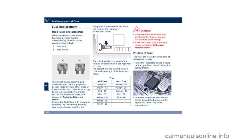
A Fuse intact
B Fuse blown
The vehicle mainly uses mini-and
maxi-fuses with blade engagement.
Besides these there are other types of
fuses provided with holes for attaching
to the cable connection terminals.
For the replacement of these fuses
contact an Authorized Maserati
Dealer .
Replace the faulty fuse with a new one
featuring the same rating, by using
appropriate forceps added in the integrated power module and inside
the cover of the rear power
distribution center.
The color identifies the value of the
fuses in amperes which is also reported
on them.
The table shows the match between
color and amperage of mini and maxi
fuses.
Type
Mini Fuse Maxi Fuse
Beige - 5 Yellow - 20
Brown - 7,5 Green - 30
Red - 10 Orange - 40
Blue-15 Red-50
Yellow - 20 Blue - 60
White - 25
Green - 30 CAUTION!
• Never replace a blown fuse with
anything other than a new and
suitable fuse (same rating).
• After replacing a fuse, if the fault
recurs, contact an Authorized
Maserati Dealer .
Position of Fuses The fuses are located in three parts of
the vehicle, namely:
• inside the integrated power module,
on the right hand side of the engine
compartment;
• inside the rear power distribution
center, behind the battery, on the
right hand side of the trunk
compartment;Maintenance and Care
7
386
Page 393 of 436

Ref. Type Function
39 Mini – 7,5A Flow meters,
tank lackage,
canister, exhaust
by-pass valve
relay coil and air
shutter
48 – –
49 Mini – 10A Pedal brake
switch-TCM
module
50 Mini – 15A +30 PCM module
51 Mini – 30A Fuel pump relay
input
52 Mini – 5A Starter solenoid
signal for PCM
and voltage
stabilizer
53 Mini – 10A AWD module
Rear Power Distribution Center • To access the center it is necessary to
lift the ground coverage of the trunk
compartment (see chapter “Tool Kit”
in section “In an Emergency”) and
remove the storage box.
• To access the fuses, release the cover
latch shown in picture. • Press the release latch and lift the lid
from this side.
• Push the lid toward the right side to
release the indicated latches on the
unit.
The table points out the position as
featured in the figure, the type and
function of the fuses on the rear area
distribution control unit. Ref. Type Function
2 Maxi – 40A BCM module
3 Maxi – 40A BCM module
4 Maxi – 30A BCM module
5 Maxi – 30A BCM module
6 Maxi – 20A Trailer harness
(not for TROFEO
version)
7 Maxi – 30A Driver door
module
8 Maxi – 30A Passenger door
module
9 Maxi – 40A Start&Stop:
voltage
stabilizer,
dashboard
10 Maxi – 40A Start&Stop:
voltage
stabilizer, body
11 Maxi – 40A “High Premium”
stereo amplifier
unit
Maxi – 20A “Premium”
stereo amplifier
unit (1)
15 Maxi – 40A HVAC front
blower relay coilMaintenance and Care
7
389