2019 MASERATI LEVANTE tow bar
[x] Cancel search: tow barPage 144 of 436

To load your vehicle properly, store
heavier items below and be sure you
distribute their weight as evenly as
possible.
Stow all loose items securely before
start driving as they could move during
the trip.
To separate trunk from passenger
compartment, the vehicle is equipped
with a rigid horizontal panel, fitted
behind the rear seat backrest. When
vehicle is at a standstill, cargo area
cover can withstand a maximum static
load of 260 lb (120 kg).
Apart from cargo area cover, the
vehicle can be also equipped with a
vertical rolling Cargo Net, to be used
to separate the cargo area from the
passenger area.
The Authorized Maserati Dealer can
provide you with any information
about the items dedicated to the
usage of the trunk (luggage
compartment mat, net, foldable
box,...), available in the "Genuine
Accessories" range.
Luggage Fasteners and
Retainers Vehicle can be equipped with fixed
and mobile anchorages on trunk floor
allowing to fasten and retain any
luggage in a convenient and safe manner. Using a special and approved
net with hooks available in the
"Genuine Accessories" range, also
large and heavy objects can be
fastened to trunk floor.
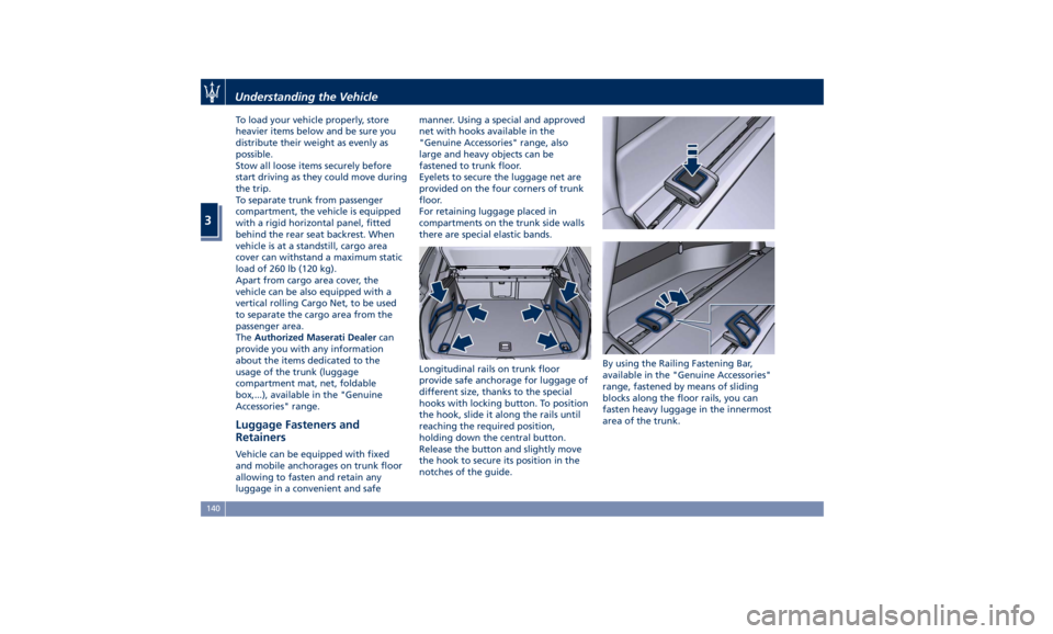
Eyelets to secure the luggage net are
provided on the four corners of trunk
floor.
For retaining luggage placed in
compartments on the trunk side walls
there are special elastic bands.
Longitudinal rails on trunk floor
provide safe anchorage for luggage of
different size, thanks to the special
hooks with locking button. To position
the hook, slide it along the rails until
reaching the required position,
holding down the central button.
Release the button and slightly move
the hook to secure its position in the
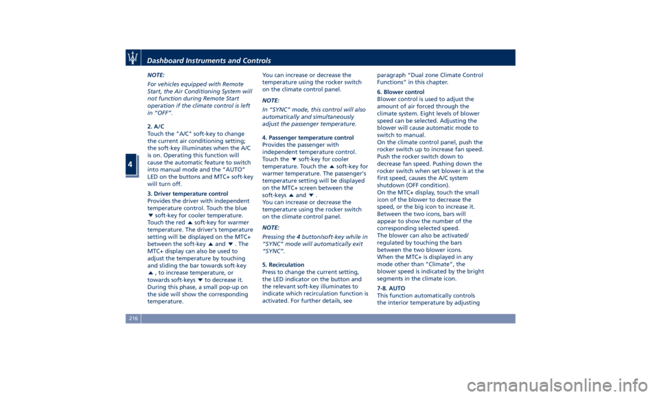
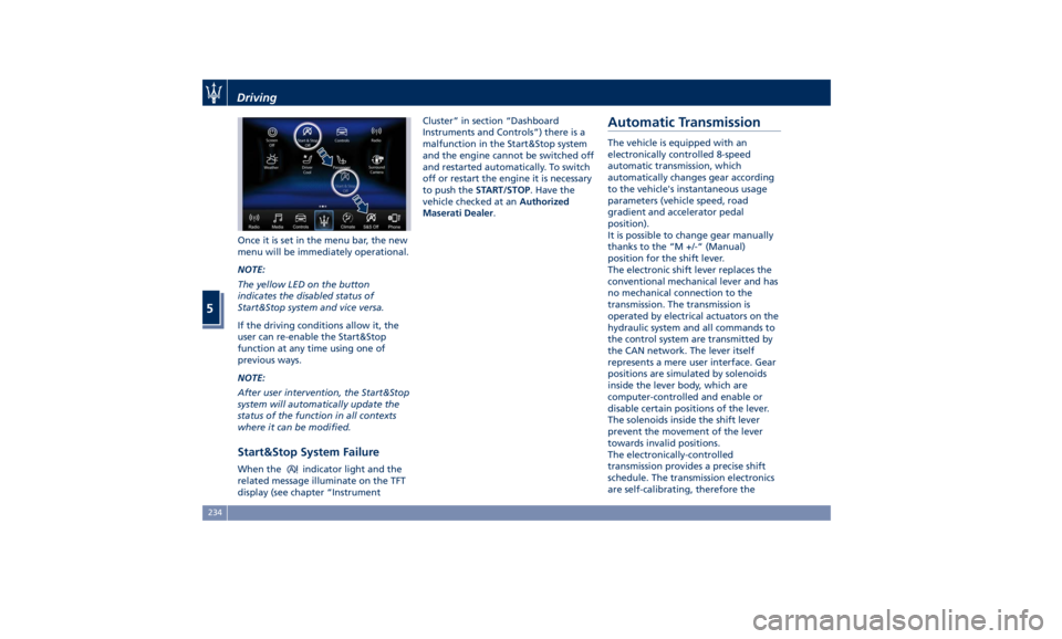
notches of the guide. By using the Railing Fastening Bar,
available in the "Genuine Accessories"
range, fastened by means of sliding
blocks along the floor rails, you can
fasten heavy luggage in the innermost
area of the trunk.Understanding the Vehicle
3
140
Page 220 of 436

NOTE:
For vehicles equipped with Remote
Start, the Air Conditioning System will
not function during Remote Start
operation if the climate control is left
in “OFF”.
2. A/C
Touch the "A/C" soft-key to change
the current air conditioning setting;
the soft-key illuminates when the A/C
is on. Operating this function will
cause the automatic feature to switch
into manual mode and the “AUTO”
LED on the buttons and MTC+ soft-key
will turn off.
3. Driver temperature control
Provides the driver with independent
temperature control. Touch the blue
soft-key for cooler temperature.
Touch the red
soft-key for warmer
temperature. The driver's temperature
setting will be displayed on the MTC+
between the soft-key
and . The
MTC+ display can also be used to
adjust the temperature by touching
and sliding the bar towards soft-key
, to increase temperature, or
towards soft-keys
to decrease it.
During this phase, a small pop-up on
the side will show the corresponding
temperature. You can increase or decrease the
temperature using the rocker switch
on the climate control panel.
NOTE:
In “SYNC” mode, this control will also
automatically and simultaneously
adjust the passenger temperature.
4. Passenger temperature control
Provides the passenger with
independent temperature control.
Touch the
soft-key for cooler
temperature. Touch the
soft-key for
warmer temperature. The passenger's
temperature setting will be displayed
on the MTC+ screen between the
soft-keys
and .
You can increase or decrease the
temperature using the rocker switch
on the climate control panel.
NOTE:
Pressing the 4 button/soft-key while in
“SYNC” mode will automatically exit
“SYNC”.
5. Recirculation
Press to change the current setting,
the LED indicator on the button and
the relevant soft-key illuminates to
indicate which recirculation function is
activated. For further details, see paragraph “Dual zone Climate Control
Functions” in this chapter.
6. Blower control
Blower control is used to adjust the
amount of air forced through the
climate system. Eight levels of blower
speed can be selected. Adjusting the
blower will cause automatic mode to
switch to manual.
On the climate control panel, push the
rocker switch up to increase fan speed.
Push the rocker switch down to
decrease fan speed. Pushing down the
rocker switch when set blower is at the
first speed, causes the A/C system
shutdown (OFF condition).
On the MTC+ display, touch the small
icon of the blower to decrease the
speed, or the big icon to increase it.
Between the two icons, bars will
appear to show the number of the
corresponding selected speed.
The blower can also be activated/
regulated by touching the bars
between the two blower icons.
When the MTC+ is displayed in any
mode other than “Climate”, the
blower speed is indicated by the bright
segments in the climate icon.
7-8. AUTO
This function automatically controls
the interior temperature by adjustingDashboard Instruments and Controls
4
216
Page 238 of 436

Once it is set in the menu bar, the new
menu will be immediately operational.
NOTE:
The yellow LED on the button
indicates the disabled status of
Start&Stop system and vice versa.
If the driving conditions allow it, the
user can re-enable the Start&Stop
function at any time using one of
previous ways.
NOTE:
After user intervention, the Start&Stop
system will automatically update the
status of the function in all contexts
where it can be modified.
Start&Stop System Failure When the indicator light and the
related message illuminate on the TFT
display (see chapter “Instrument Cluster” in section “Dashboard
Instruments and Controls”) there is a
malfunction in the Start&Stop system
and the engine cannot be switched off
and restarted automatically. To switch
off or restart the engine it is necessary
to push the START/STOP . Have the
vehicle checked at an Authorized
Maserati Dealer .
Automatic Transmission The vehicle is equipped with an
electronically controlled 8-speed
automatic transmission, which
automatically changes gear according
to the vehicle's instantaneous usage
parameters (vehicle speed, road
gradient and accelerator pedal
position).
It is possible to change gear manually
thanks to the “M +/-“ (Manual)
position for the shift lever.
The electronic shift lever replaces the
conventional mechanical lever and has
no mechanical connection to the
transmission. The transmission is
operated by electrical actuators on the
hydraulic system and all commands to
the control system are transmitted by
the CAN network. The lever itself
represents a mere user interface. Gear
positions are simulated by solenoids
inside the lever body, which are
computer-controlled and enable or
disable certain positions of the lever.
The solenoids inside the shift lever
prevent the movement of the lever
towards invalid positions.
The electronically-controlled
transmission provides a precise shift
schedule. The transmission electronics
are self-calibrating, therefore theDriving
5
234
Page 296 of 436

To increase or decrease the number of
bars, corresponding to the gap from
vehicle ahead, press and release the
distance setting button. Each press and release of the button
changes the gap starting from 3 bars
(default distance) and moving in a
sequential way towards the minimum
distance: 3 → 2 → 1 → 4 → 3 → 2 → 1 → 4 and so
on.
If there is no vehicle ahead, the vehicle
will maintain the set speed. If a slower
moving vehicle is detected in the same
lane, the system displays the target
vehicle icon before the bars. From that
moment, the system adjusts the vehicle
speed automatically to maintain the
distance setting, regardless of the set
speed.
The vehicle will then maintain the set
distance until:
• The vehicle ahead accelerates to a
speed above the set speed.
• The vehicle ahead moves out of the
lane or view of the sensor.
• The distance setting is changed. • The driver disables the system.
The maximum braking applied by ACC
is limited; however, the driver can
always apply the brakes manually, if
necessary. Any time the ACC system
automatically operates the brakes, the
brake lights will turn on as if the driver
was braking.
A Proximity Warning on display will
alert the driver if ACC predicts that its
maximum braking level is not
sufficient to maintain the set distance.
If this occurs, a visual alert will flash on
the display and a chime will sound
while ACC continues to apply its
maximum braking capacity.Driver Assist Page
Non-Driver Assist PageDriving
5
292
Page 432 of 436

Passenger Seat Belts ..........61
Seat Belt Reminder Light ..... .164
Seat Belts and Pregnant Women . .65
Seat Belts Pretensioners ........63
Three-Point Seat Belts .........59
Three-Point Seat Belts Height
Adjustment ................61
Three-Point Seat Belts Untwisting
Procedure .................61
Three-Point Seat Belts Use
Instructions ................59
Using the Seat Belt in Automatic
Locking Retractor Mode (ALR) . . .63
Seats ......................97
Driver Memory Seat ........ .101
Easy Entry/Exit Seats ........ .102
Front Heated Seats ...........99
Front Power Seats ............97
Front Ventilated Seats ....... .100
Power Lumbar Seats ..........98
Rear Armrest ............. .104
Rear Seat Folding Seatback . . . .103
Rear Seats ............... .103
Rear Side Heated Seats ...... .104
Seat Adjustment .............98
Service .....................10
Siri Smart Personal Assistant .... .225
SmartBeam System ........... .116
Smoking Kit ................ .137
Snow Chains ............... .328
Spare parts service
Genuine Parts ..............13
Scheduled Maintenance .......13 Spare Parts Service .............13
SRS (Supplemental Restraint
System) ....................65
Start&Stop System ........... .230
Occupant Safety Function .... .232
Start&Stop Active Indicator . . . .163
Start&Stop Disable Indicator . . . .182
Start&Stop Failure Indicator
Light ................... .182
Start&Stop Function Disabling
Indicator ................ .232
Start&Stop Menu .......... .172
Start&Stop System Failure .... .234
Start the Engine
Engine Start Failure ......... .229
Engine Turn Off ........... .230
Steering Wheel .............
.108
Heated
Steering Wheel ...... .108
Phone
and Voice Controls on
Steering Wheel ............ .224
Sunroof
Initialization Procedure ...... .149
Pinch Protect Feature ....... .149
Slide Opening Sunroof ....... .148
Sunroof Maintenance ....... .150
Venting Sunroof ........... .149
Sunshades ...................48
Sun Visors ................. .137
Surround View Camera System ....87
Symbols ....................14
Danger Symbols .............14 Symbols of Prohibitions and
Compulsory Measures .........14
Tank fuel refill .............. .336
TCS (Traction Control System) .... .275
Technical Data .............. .411
Telltales
Telltales on Speedometer ..... .161
Telltales on Tachometer ...... .163
Tires
Change a Tire ............. .351
Compact spare tire ......... .329
Department of Transportation
Uniform Tire Quality Grades . . . .325
General Information ........ .321
Inflation Pressure .......... .420
Pneumatic Suspension Mode for
Wheel Change ............ .329
Punctured Tire, use ......... .351
Replacement Tires .......... .327
Tire Pressure .............. .325
Tire Pressure Checkup ....... .326
Tire Safety Information ...... .321
TPMS - Tire Pressure Monitoring
System .................. .329
Tread Wear Indicators ....... .326
Winter Tires .............. .328
ToolKit................... .348
Towing
Towing a Disabled Vehicle .... .360
Towing the Vehicle ......... .360
Use
the Vehicle Tow Hook .... .360
Vehicle Towing Conditions .... .360Index
9 428