2019 MASERATI LEVANTE battery
[x] Cancel search: batteryPage 157 of 436

hand-held transmitters” from second
step and follow all remaining steps.
Using HomeLink ®
To operate, press and release the
programmed HomeLink ®
button.
Activation will now occur for the
programmed device (i.e., garage door
opener, gate operator, security system,
entry door lock, home/office lighting,
etc.). The hand-held transmitter of the
device may also be used at any time.
Security It is advisable to erase all channels
before you sell or turn in your vehicle.
To erase the channels press and hold
the two outside HomeLink ®
buttons (I
and III) until the indicator light starts
flashing (after approximately 20
seconds).
The HomeLink ®
Universal Transceiver
is disabled when the vehicle security
alarm is active (see “Vehicle security
alarm” in section “Before Starting”).
Troubleshooting Tips If you are having trouble while
programming HomeLink ®
, here are
some of the most common solutions:
• Replace the battery in the original
hand-held transmitter. • Press the LEARN button on the
garage door opener to complete the
training for a rolling code.
• Did you unplug the device for
programming and forgot to plug it
back in?
If you have any problems, or require
assistance, please call toll-free
1–800–355–3515 or, on the Internet at
www.HomeLink.com for information
or assistance.
Radio Frequency Device -
Regulatory Information The “Regulatory Information” for all
the radio frequency and radar devices
can be consulted by accessing the
"Services" section on the website
www.maserati.com. Understanding the Vehicle
3
153
Page 171 of 436

sector 23, only the main menu number
and the scroll arrows remain displayed
in the sector 3 , left side.
Within a submenu, press and release
the switch in the
and arrow
directions to scroll the menu.
Press the
button to return to the
main menu from an item of interest or
from an information screen.
Main Menu & Submenu Content
Overview
1. MAIN MENU
• View speed in mph or km/h
2. VEHICLE INFO
• Tire Pressure
• Transmission Temperature
• Oil Temperature
• Oil Pressure
• Battery Voltage
• Maintenance 3. DRIVE MODE
• Drive Mode - Ride Height - Torque
Distribution - Powertrain status - ESC
status - Suspension stiffness status
4. Driver Assist (if equipped)
• Shows the status of any active driver
assist systems: CC, ACC, LKA and
HAS. Graphics in the main area of
TFT display only refer to ACC, LKA
and HAS systems
• LKA (LaneSense) status
5. FUEL ECONOMY
• Average, Range, Current gage
6. TRIP
• Trip A: Average, Avg. speed, Elapsed
time, Distance
• Trip B: Average, Avg. speed, Elapsed
time, Distance
7. START&STOP
• Messages relating to the Start&Stop
function
8. AUDIO
• Information concerning audio status
according to current media source,
track and station.
• Information on phone incoming call.
9. STORED MESSAGES
10. VEHICLE SETTINGS • Speed Warning: enables, disables or
sets the speed limit represented in
the dynamic icon on the TFT display
• Auto apply Off/On of the Electric
Parking Brake
• Interior Lighting
– Backlighting
– Ambient Lighting
• SCREEN SETUP
– Upper Left
– Upper Right
– Main Menu: Line 1
– Main Menu: Line 2
– Main Menu: Line 3
– MPH km/h Display On/Off
– Main Menu Navigation
– Outline Coloring
– Key-On Display
– Key-Off Display
– Defaults
Messages on Main Display Area
The main display area also displays
"pop up" messages. These pop up
messages fall into several categories:
• Five-Second Stored Messages
When the appropriate conditions
occur, this type of message appears
on the main display area for five
seconds and then returns to the
previous screen. Most of the
messages of this type are thenDashboard Instruments and Controls
4
167
Page 174 of 436

NOTE:
This strategy is also applicable in the
Transmission Temperature and Oil
Pressure information screen.
• Oil Pressure
Displays the current engine oil
pressure level.
• Battery Voltage
Displays the current battery voltage.
• Maintenance (service)
Displays mileage and days remaining
to the execution of scheduled
maintenance service.
Press and release the
button to
return to the main menu.
3. DRIVE MODE
Press and release the switch in the
or arrow directions until this
menu item is displayed. The screen graphically shows the Drive Mode: OFF
ROAD, I.C.E., NORMAL, SPORT, CORSA
(TROFEO version only) and
(Suspension) set by the user through
the relevant controls.
The display main area will show
vehicle image with parameters and
color-coded components affected by
the selected drive mode.
The image will show the following
parameters:
• current ground clearance indicated
in front of vehicle and on a specific
indicator on top right corner;
• torque distribution percentage
indicated under the arrow in front of
the wheels;
• selected drive mode (in the example
shown: I.C.E.).
For any color-coded components, color
depends on settings of:
• ESC: identified by wheel color.
• PowerTrain: identified by engine +
transmission unit color.
• Suspension
: identified by the
color of the four shock absorbers. For every drive mode, function (ESC,
PowerTrain and Suspension) and color
of the components shown are matched
as follows:
NOTE:
To set drive parameters according to
own needs and path, refer to chapter
“Drive Mode” and “Off-road Drive” in
section “Driving”.
Press and release the
button to
return to the main menu.Dashboard Instruments and Controls
4
170
Page 184 of 436

the hood (see “Maintenance
Procedures” in section “Maintenance
and Care”).
Electric Power Steering Failure
Warning Light
This warning light, and the
related message, illuminate
when the electric power
steering is not operating and
needs service.
If the warning light is on, steering
assistance may be not available.
WARNING!
After battery disconnection event, the
warning light may be on. In this case,
start the engine and perform a
steering wheel stroke end to end.
If the problem persists, contact an
Authorized
Maserati Dealer .
Catalyst Over Temperature Warning
Light
This warning light, and the
related message, light up if
the engine runs irregularly
with consequent high
temperature in the exhaust system. WARNING!
• If the warning light is accompanied
by the message “Catalyst Temp
Getting Hot Reduce Speed”: the
temperature of the catalytic
converters is too high. The driver
must slow down immediately until
the warning light turns off.
• If the message “Catalyst Temp Hot
Stop Safely Wait To Cool” appears
after decelerating: the temperature
in the catalytic converters has
reached a dangerous level and the
catalytic converters could be
damaged. Drive slowly to the
nearest Authorized Maserati Dealer.
• Maserati declines all responsibility
for whatever damage deriving from
non-compliance with the above
mentioned warnings.
Door Ajar Indicator
This
indicator illuminates
when one
or more doors are
ajar. The indicator will show
which door is ajar. When one
or more doors are open, a related
message will be displayed if the vehicle
is running at a speed of 5 mph (8
km/h) or faster. Liftgate and Hood Ajar Indicators
These light indicators will
illuminate to indicate that the
liftgate and/or the hood are
ajar.
When the liftgate or the hood
is open, a related message will
be displayed besides the light
if the vehicle is running at a speed of
5 mph (8 km/h) or faster.
Electronic Throttle Control (ETC)
Indicator
This indicator light indicates a
failure of the Electronic
Throttle Control (ETC) system.
If the indicator turns on while
driving (a torque decrease is possible),
have the system checked by an
Authorized Maserati Dealer .
When detecting a failure, the light
indicator will illuminate while the
engine is running.
If the indicator remains lit with the
engine running, you can still drive your
vehicle. However, contact an
Authorized Maserati Dealer as soon as
possible.
If the indicator is flashing while the
engine is running, immediate service is
required. You may experience reduced
performance, an elevated/rough idleDashboard Instruments and Controls
4
180
Page 216 of 436

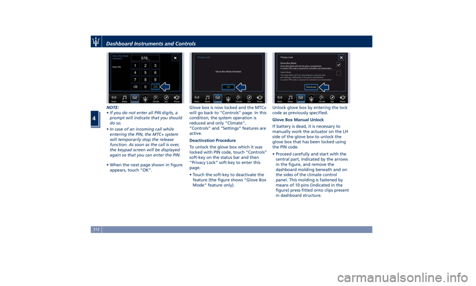
NOTE:
• If you do not enter all PIN digits, a
prompt will indicate that you should
do so.
• In case of an incoming call while
entering the PIN, the MTC+ system
will temporarily stop the release
function. As soon as the call is over,
the keypad screen will be displayed
again so that you can enter the PIN.
• When the next page shown in figure
appears, touch “OK”. Glove box is now locked and the MTC+
will go back to “Controls” page. In this
condition, the system operation is
reduced and only “Climate”,
“Controls” and “Settings” features are
active.
Deactivation Procedure
To unlock the glove box which it was
locked with PIN code, touch “Controls”
soft-key on the status bar and then
“Privacy Lock” soft-key to enter this
page.
• Touch the soft-key to deactivate the
feature (the figure shows "Glove Box
Mode" feature only). Unlock glove box by entering the lock
code as previously specified.
Glove Box Manual Unlock
If battery is dead, it is necessary to
manually work the actuator on the LH
side of the glove box to unlock the
glove box that has been locked using
the PIN code.
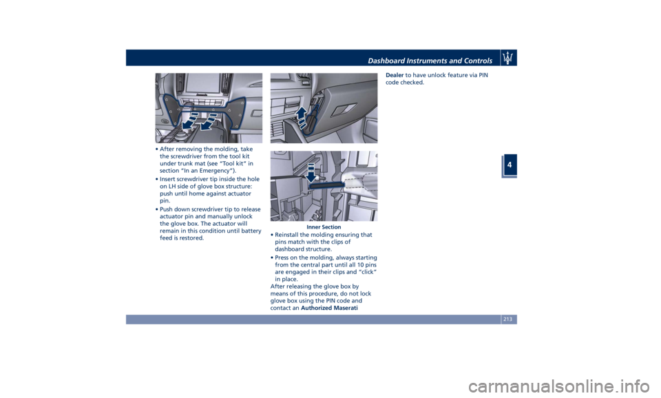
• Proceed carefully and start with the
central part, indicated by the arrows
in the figure, and remove the
dashboard molding beneath and on
the sides of the climate control
panel. This molding is fastened by
means of 10 pins (indicated in the
figure) press-fitted onto clips present
in dashboard structure.Dashboard Instruments and Controls
4
212
Page 217 of 436

• After removing the molding, take
the screwdriver from the tool kit
under trunk mat (see “Tool kit” in
section “In an Emergency”).
• Insert screwdriver tip inside the hole
on LH side of glove box structure:
push until home against actuator
pin.
• Push down screwdriver tip to release
actuator pin and manually unlock
the glove box. The actuator will
remain in this condition until battery
feed is restored. • Reinstall the molding ensuring that
pins match with the clips of
dashboard structure.
• Press on the molding, always starting
from the central part until all 10 pins
are engaged in their clips and “click”
in place.
After releasing the glove box by
means of this procedure, do not lock
glove box using the PIN code and
contact an Authorized Maserati Dealer to have unlock feature via PIN
code checked.
Inner SectionDashboard Instruments and Controls
4
213
Page 233 of 436

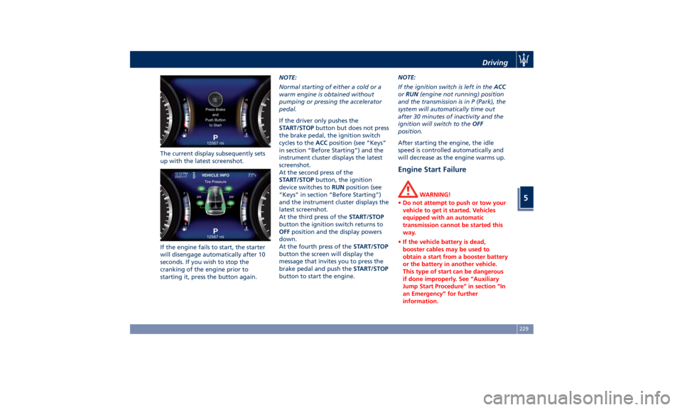
The current display subsequently sets
up with the latest screenshot.
If the engine fails to start, the starter
will disengage automatically after 10
seconds. If you wish to stop the
cranking of the engine prior to
starting it, press the button again. NOTE:
Normal starting of either a cold or a
warm engine is obtained without
pumping or pressing the accelerator
pedal.
If the driver only pushes the
START/STOP button but does not press
the brake pedal, the ignition switch
cycles to the ACC position (see “Keys”
in section “Before Starting”) and the
instrument cluster displays the latest
screenshot.
At the second press of the
START/STOP button, the ignition
device switches to RUN position (see
“Keys” in section “Before Starting”)
and the instrument cluster displays the
latest screenshot.
At the third press of the START/STOP
button the ignition switch returns to
OFF position and the display powers
down.
At the fourth press of the START/STOP
button the screen will display the
message that invites you to press the
brake pedal and push the START/STOP
button to start the engine. NOTE:
If the ignition switch is left in the ACC
or RUN (engine not running) position
and the transmission is in P (Park), the
system will automatically time out
after 30 minutes of inactivity and the
ignition will switch to the OFF
position.
After starting the engine, the idle
speed is controlled automatically and
will decrease as the engine warms up.
Engine Start Failure WARNING!
• Do not attempt to push or tow your
vehicle to get it started. Vehicles
equipped with an automatic
transmission cannot be started this
way.
• If the vehicle battery is dead,
booster cables may be used to
obtain a start from a booster battery
or the battery in another vehicle.
This type of start can be dangerous
if done improperly. See “Auxiliary
Jump Start Procedure” in section “In
an Emergency” for further
information.Driving
5
229
Page 235 of 436

remain in “AutoStop” with engine off.
Pressing the brake pedal and shifting
transmission into D (Drive) or R
(Reverse) will deactivate the
“AutoStop” condition and restart the
engine.
Start&Stop Deactivated Start&Stop function is deactivated
under the following conditions:
• When SPORT drive mode is activated.
• When
(ESC OFF) drive mode is
activated.
• When ride height is set to Off Road 1
or Off Road 2.
• If it has been disabled through the
main menu item “Start & Stop” via
the controls on the right side of the
steering wheel (see chapter
“Instrument cluster” in section
“Dashboard Instruments and
Controls”) or via the MTC+ in the “Controls” page (see “MTC+
"Controls" Screen” in section
“Dashboard Instruments and
Controls”).
Start&Stop Not Active For keeping driving safety, interior
comfort and a correct functioning of
engine and vehicle, the Start&Stop
function does not activate under the
following conditions:
• When the driver’s seat belt is
unbuckled (see example in picture).
• When the driver door is open.
• When the fuel level is too low.
• When the vehicle is stopped on a
very steep road.
• When the vehicle is stopped with
steered wheels (over 135° of steering
wheel angle for each part). • When the vehicle is maneuvering:
shift lever in R (Reverse).
• When the temperature conditions
inside the vehicle do not correspond
to the air conditioning setting.
• When the front and rear “defroster”
function is activated.
• When the engine coolant and the
engine oil temperature are not on
proper functioning level.
• When the external temperature is
too cold.
• When the battery charge is below
safety value.
• When the previous stop had just
happened (few seconds) and the
minimum speed has not yet been
achieved.
• Shortly after R (Reverse) has been set
or when driving under a certain
speed level.
• When the hood is open.
• The sensors managing the
Start&Stop have been damaged.
• Start&Stop system faults are present.
• When Adaptive Cruise Control (ACC)
and/or Highway Assist (HAS) system
are engaged.Driving
5
231