2019 MASERATI LEVANTE battery
[x] Cancel search: batteryPage 236 of 436
Automatic Restarting of the
Engine The engine may automatically restart,
before the brake pedal has been
released, when one of the following
conditions occurs:
• The SPORT drive mode or
(ESC
OFF) drive mode is being activated.
• If the Start&Stop function has been
disabled through the main menu
voice “Start & Stop” (see chapter
“Instrument cluster” in section
“Dashboard Instruments and
Controls”) or via MTC+ in the
“Controls” page (see “MTC+
“Controls “Screen” in the section
“Dashboard Instruments and
Controls”).
• If shift lever is moved to R (Reverse).
• If the steering wheel is moved to
steer the wheels.
• When the temperature conditions
inside the vehicle do not correspond
to the air conditioning setting.
• When changing the temperature
setting on the air conditioning.
• When the defroster function is being
activated.
• When the battery charge is below
safety value. • When the accelerator pedal is being
pressed (together with the brake
pedal).
• If a long time has passed since the
last automatic stop of the engine.
Occupants Safety Function To enhance occupants safety, the
Start&Stop system monitors if the
driver is present and does not allow
automatic restarting of the engine if
one of the following maneuvers is
being performed while in “AutoStop”
condition:
• The driver unbuckles his/her seat belt
and releases the brake pedal.
• The driver opens the door and
releases the brake pedal.
• The driver unbuckles the seat belt
and opens the door.
• The driver opens the hood.
All the above-mentioned conditions
deactive the Start&Stop function (the
“AutoStart” is deactivated and the
engine remains off) and the
transmission shift automatically in P
(Park).
The
telltale will flash to indicate
the Start&Stop function disabling. To
restart the engine it is necessary to
press the brake pedal and push the
START/STOP button. Move the shift lever to D (Drive) to
drive away.
WARNING!
• Even when the vehicle is stopped in
the “Stop (AutoStop)” phase, the
driver is responsible for the vehicle
and the occupants and shall take
care of what happens inside and
outside the vehicle.
• Even when the vehicle is stopped
within the “Stop (AutoStop)” phase,
the vehicle driver is responsible for
the vehicle, the vehicle’s occupants
and the vehicle’s surrounding area.
Never leave the vehicle unattended
with the engine running; doing so
poses a risk of danger. It is a good
practice to always ensure to set the
parking brake and place the
transmission gear selector lever into
the P (Park) position, thereby
ensuring the vehicle will not move,
when performing any vehicle checks,
maintenance and/or service
procedures on the vehicle.
Start&Stop Function Disabling Under certain driving conditions, when
frequent stops and restarts of the
engine may become annoying, it isDriving
5
232
Page 264 of 436
the position of the vehicle with little
suspension movements to ensure a
proper appearance.
Display Messages
After shifting selector to change
position, a pop-up message will
indicate for 5 seconds when set
position has been reached (after
pneumatic suspension system
intervention that might last up to 30
seconds).
This type of message will be displayed
only if the option to view all
pneumatic suspension system messages
was set (For further details, refer to
“MTC+ Settings” in section
“Dashboard Instruments and
Controls”).
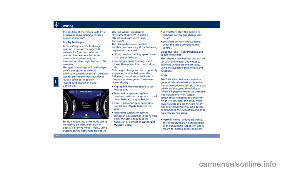
Set ride height and drive mode can be
monitored on instrument cluster
display via “Drive mode” menu, using
buttons on the right-hand side of the steering wheel (see chapter
“Instrument Cluster” in section
“Dashboard Instruments and
Controls”).
The change from one position to
another can occur only if the following
requirements are met.
• Lifting: engine running, speed lower
than preset limit, etc.
• Lowering: engine running, speed
lower than preset limit, doors closed,
etc.
Ride height change can be temporarily
suspended or disabled under the
following conditions, as indicated in
the pop-up messages on instrument
cluster display.
• High speed: decrease speed to set
new height.
• Pneumatic suspension system
overheat: wait for the system to cool
down before changing height.
• Door(s) and/or liftgate open: close
door(s) and liftgate to lower the
vehicle.
• Pneumatic suspension system
temporarily disabled or in fault: wait
a few minutes and repeat the
operation or contact an Authorized
Maserati Dealer . • Low battery: start the engine to
recharge battery and change ride
height.
• Entry/Exit position not available:
check the cause preventing this
control.
Using the Ride Height Positions and
speed Thresholds
The different ride heights that can be
set with the selector allow user to
drive the vehicle on and off road,
using the available drive modes and
functions.
NOTE:
The indications below explain as a
general rule which selector position
has to be used in certain situations and
which are the speed thresholds at
which it is possible to set the available
ride height and when system
automatically switches to a different
height. In any case, the driver must
always assess and set the ride height
and drive mode most suitable to the
conditions of the current driving path
on a case by case basis.
• Normal : normal ground clearance.
This is the standard height position
of the pneumatic suspension and is
meant for normal road conditions.Driving
5
260
Page 268 of 436

Active Alternator To improve overall efficiency by
reducing the auxiliary loads on the
engine, the vehicle is equipped with a
smart alternator that is mainly active
in the latter energy balance phases
(for example, during braking, coasting
and overloading). The alternator
becomes active when the battery
charge is insufficient and when the
vehicle exits from the braking and
overload situations.
Active Alternator Feature (if feature is
available)
In the I.C.E. screen, the user can display
in the form of dynamic bars some
informative parameters on the state of
battery charge ("CHARGE"), efficiency
of drive style ("EFFICIENCY") and the
matured economy (“
” bonus range)
expressed in miles (mi) or kilometres
(km). The bonus range (about 37 mi / 60 km
for each full of fuel) is automatically
reset every time the vehicle is refueled.
Off-Road Drive This vehicle is equipped with a specific
“Off Road” driving mode which allows
to drive through various terrain
conditions (rock, mud, sand), also
uphill and downhill, eventually in
condition of lateral inclination.
To set the "OFF ROAD" drive mode,
please see the paragraphs “Setting the
Drive Mode” and “Setting Ride
Height” of chapter “Drive Mode” in
this section.
In order to enhance this specific
performance, the "OFF ROAD" drive
mode modifies the setting of:
• Ride height;
• Engine, transmission calibration;
• Suspensions.
When “OFF ROAD” is selected, ride
height is set to “Off Road 1” (vehicle is
higher by approx. 1 in / 25 mm).
It is possible to select ride height “Off
Road 2” (vehicle is raised by approx.
1.5 in / 40 mm) using the ride height
selector.
“OFF ROAD” drive mode is limited up
to a max speed of 56 mph (90 km/h). In
case the vehicle speed should exceed
this limit, the drive mode will be
de-selected automatically and the
drive mode will return to “NORMAL”.Driving
5
264
Page 274 of 436
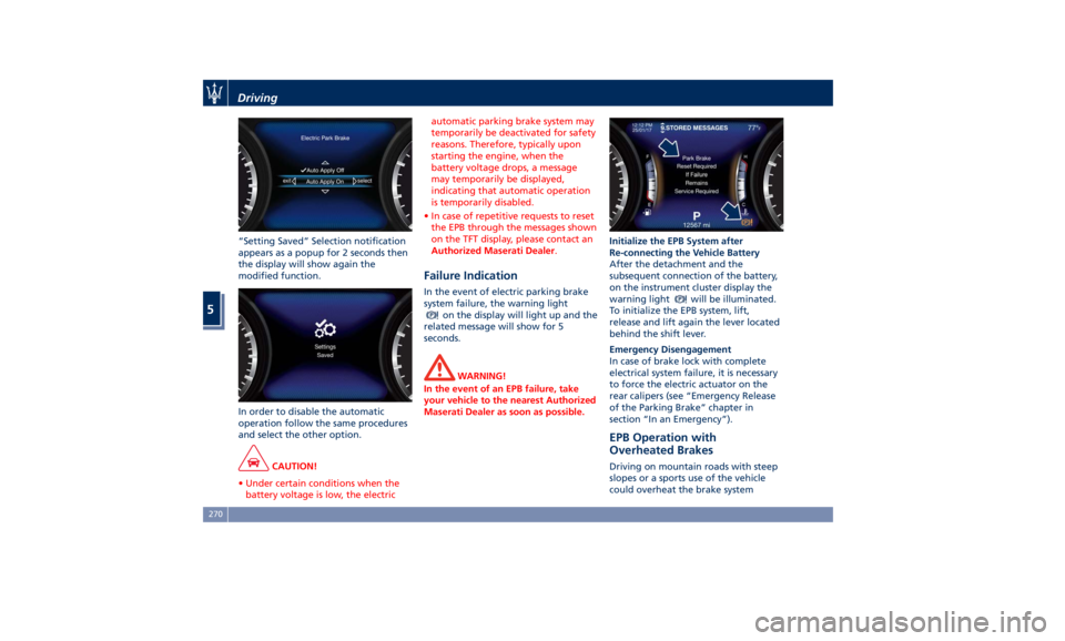
“Setting Saved” Selection notification
appears as a popup for 2 seconds then
the display will show again the
modified function.
In order to disable the automatic
operation follow the same procedures
and select the other option.
CAUTION!
• Under certain conditions when the
battery voltage is low, the electric automatic parking brake system may
temporarily be deactivated for safety
reasons. Therefore, typically upon
starting the engine, when the
battery voltage drops, a message
may temporarily be displayed,
indicating that automatic operation
is temporarily disabled.
• In case of repetitive requests to reset
the EPB through the messages shown
on the TFT display, please contact an
Authorized Maserati Dealer .
Failure Indication In the event of electric parking brake
system failure, the warning light
on the display will light up and the
related message will show for 5
seconds.
WARNING!
In the event of an EPB failure, take
your vehicle to the nearest Authorized
Maserati Dealer as soon as possible. Initialize the EPB System after
Re-connecting
the V ehicle Battery
After the detachment and the
subsequent connection of the battery,
on the instrument cluster display the
warning light
will be illuminated.
To initialize the EPB system, lift,
release and lift again the lever located
behind the shift lever.
Emergency Disengagement
In case of brake lock with complete
electrical system failure, it is necessary
to force the electric actuator on the
rear calipers (see “Emergency Release
of the Parking Brake” chapter in
section “In an Emergency”).
EPB Operation with
Overheated Brakes Driving on mountain roads with steep
slopes or a sports use of the vehicle
could overheat the brake systemDriving
5
270
Page 354 of 436
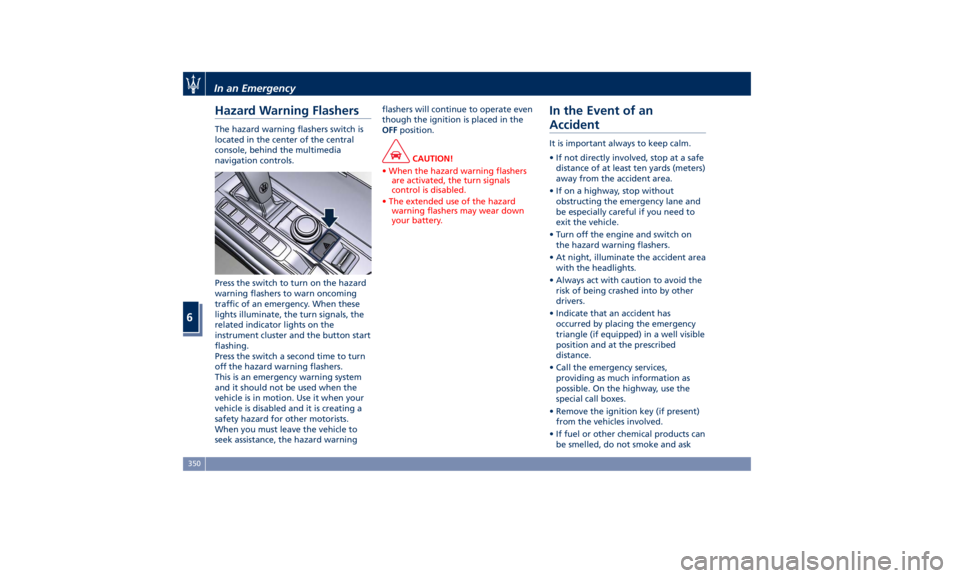
Hazard Warning Flashers The hazard warning flashers switch is
located in the center of the central
console, behind the multimedia
navigation controls.
Press the switch to turn on the hazard
warning flashers to warn oncoming
traffic of an emergency. When these
lights illuminate, the turn signals, the
related indicator lights on the
instrument cluster and the button start
flashing.
Press the switch a second time to turn
off the hazard warning flashers.
This is an emergency warning system
and it should not be used when the
vehicle is in motion. Use it when your
vehicle is disabled and it is creating a
safety hazard for other motorists.
When you must leave the vehicle to
seek assistance, the hazard warning flashers will continue to operate even
though the ignition is placed in the
OFF position.
CAUTION!
• When the hazard warning flashers
are activated, the turn signals
control is disabled.
• The extended use of the hazard
warning flashers may wear down
your battery.
In the Event of an
Accident It is important always to keep calm.
• If not directly involved, stop at a safe
distance of at least ten yards (meters)
away from the accident area.
• If on a highway, stop without
obstructing the emergency lane and
be especially careful if you need to
exit the vehicle.
• Turn off the engine and switch on
the hazard warning flashers.
• At night, illuminate the accident area
with the headlights.
• Always act with caution to avoid the
risk of being crashed into by other
drivers.
• Indicate that an accident has
occurred by placing the emergency
triangle (if equipped) in a well visible
position and at the prescribed
distance.
• Call the emergency services,
providing as much information as
possible. On the highway, use the
special call boxes.
• Remove the ignition key (if present)
from the vehicles involved.
• If fuel or other chemical products can
be smelled, do not smoke and askIn an Emergency
6
350
Page 357 of 436
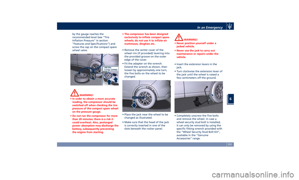
by the gauge reaches the
recommended level (see “Tire
Inflation Pressure” in section
“Features and Specifications”) and
screw the cap on the compact spare
wheel valve.
WARNING!
• In order to obtain a more accurate
reading, the compressor should be
switched off when checking the tire
pressure of the compact spare wheel
on the pressure gauge.
• Do not run the compressor for more
than 20 minutes: there is a risk it
could overheat. Also, prolonged
power absorption may discharge the
battery, subsequently preventing
the engine from starting. • The compressor has been designed
exclusively to inflate compact spare
wheels; do not use it to inflate air
mattresses, dinghies etc.
• Remove the center cover of the
wheel
rim (if provided) levering into
the provided groove on the outer
edge of the cover.
• Fit the adapter on the wrench.
Extend the wrench as shown, then
loosen by approximately one turn,
the five bolts on the wheel to be
changed.
• Place the jack near the wheel to be
changed as illustrated.
• Make sure that the head of the jack
is correctly inserted in one of the
slots beneath the rocker panel. WARNING!
• Never position yourself under a
jacked vehicle.
• Never use the jack to carry out
maintenance or repairs under the
vehicle.
• Insert the extension levers in the
jack.
•
Turn clockwise
the extension lever of
the jack until the wheel is raised a
few centimeters off the ground.
• Completely unscrew the five bolts
and remove the wheel. In case a
wheel security stud bolt is installed,
it can only be removed by using the
specific fitting wrench provided with
the “Wheel Security Stud Bolt Kit”,
available in the “Genuine
Accessories” range.In an Emergency
6
353
Page 360 of 436
Emergency Release of the
Parking Brake In the event the electric parking brake
locks due to a system failure (see
“Parking Brake” in section “Driving”),
it is not possible to move the vehicle,
since the actuator that operates on the
brake pad inside each rear caliper will
lock the rear wheels.
After verifying that the battery is
sufficiently charged (otherwise use an
external power source connected to
the vehicle electric system to operate
the EPB control lever and try to unlock
the parking brake), for moving the
vehicle it is necessary to force the
actuator to release the rear brake
discs. Contact the Authorized Maserati
Dealer to carry out this operation.
WARNING!
If the parking brake has been
activated in manual or automatic
mode and it is not possible to release
it by operating on the lever of the
central console, do not move the
vehicle since rear brake calipers might
be damaged. For more information on vehicle towing see "Towing a Disabled
Vehicle" chapter in this section.
Transmission Manual
Release of P (Park)
Position The manual disengagement of the
shift from P (Park) has the purpose to
allow towing the vehicle if not
normally possible using the shift lever
(such as inability to start the engine).
This procedure is exclusively intended
for emergency situations, only!
WARNING!
Always secure your vehicle by fully
applying the parking brake, before
activating the manual park release.
Activating the manual park release
could allow your vehicle to roll away
if it is not secured by the parking
brake. Activating the manual park
release on an unsecured vehicle could
lead to serious injury or death for
those in or around the vehicle.
The cover that allows the emergency
manual
park release is
located on the
left part of the driver’s foot well.
• Lift the mat on the driver side to
access the cover.
• Slip the cover from its seat.In an Emergency
6
356
Page 361 of 436
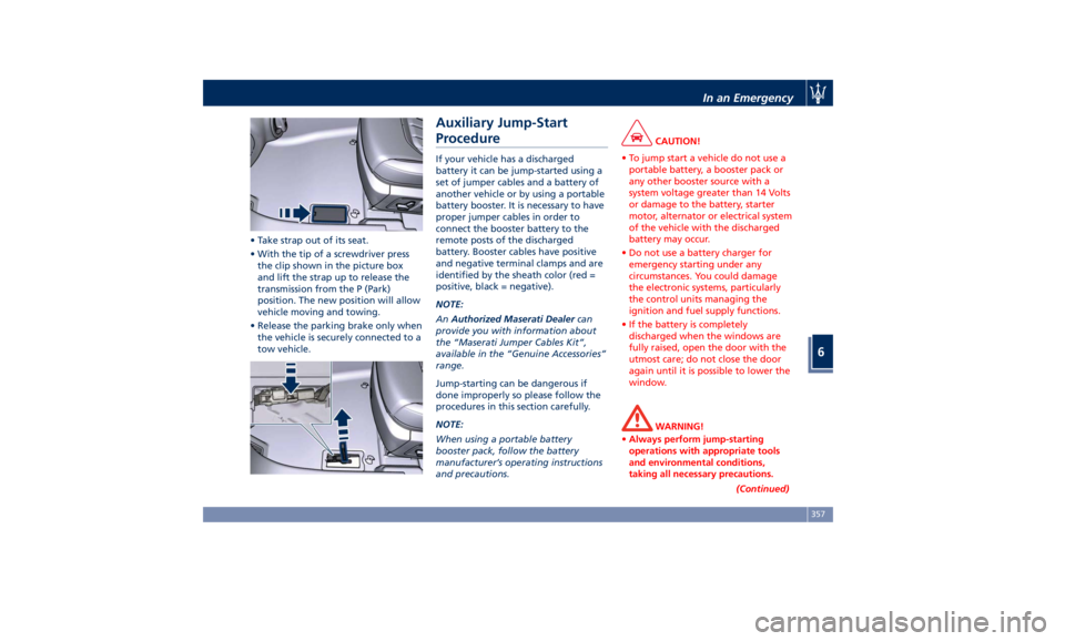
• Take strap out of its seat.
• With the tip of a screwdriver press
the clip shown in the picture box
and lift the strap up to release the
transmission from the P (Park)
position. The new position will allow
vehicle moving and towing.
• Release the parking brake only when
the vehicle is securely connected to a
tow vehicle. Auxiliary Jump-Start
Procedure If your vehicle has a discharged
battery it can be jump-started using a
set of jumper cables and a battery of
another vehicle or by using a portable
battery booster. It is necessary to have
proper jumper cables in order to
connect the booster battery to the
remote posts of the discharged
battery. Booster cables have positive
and negative terminal clamps and are
identified by the sheath color (red =
positive, black = negative).
NOTE:
An Authorized Maserati Dealer can
provide you with information about
the “Maserati Jumper Cables Kit”,
available in the “Genuine Accessories”
range.
Jump-starting can be dangerous if
done improperly so please follow the
procedures in this section carefully.
NOTE:
When using a portable battery
booster pack, follow the battery
manufacturer’s operating instructions
and precautions. CAUTION!
• To jump start a vehicle do not use a
portable battery, a booster pack or
any other booster source with a
system voltage greater than 14 Volts
or damage to the battery, starter
motor, alternator or electrical system
of the vehicle with the discharged
battery may occur.
• Do not use a battery charger for
emergency starting under any
circumstances. You could damage
the electronic systems, particularly
the control units managing the
ignition and fuel supply functions.
• If the battery is completely
discharged when the windows are
fully raised, open the door with the
utmost care; do not close the door
again until it is possible to lower the
window.
WARNING!
• Always perform jump-starting
operations with appropriate tools
and environmental conditions,
taking all necessary precautions.
(Continued)In an Emergency
6
357