2019 MASERATI LEVANTE battery
[x] Cancel search: batteryPage 75 of 436

inflates. This especially applies to
children.
Supplemental Side Air Bag Inflatable
Curtain (SABIC) Inflator Units
During collisions where the impact is
confined to a particular area of the
side of the vehicle, the ORC may
deploy the SABIC air bags, depending
on the severity and type of collision. In
these events, the ORC will deploy the
SABIC only on the impact side of the
vehicle. A quantity of non-toxic gas is
generated to inflate the side curtain
air bag.
The inflating side curtain air bag
pushes the head/s of the occupant/s
seating in the outside seats from the
edge of the headliner out of the way
and covers the window. The air bag
inflates with enough force to possibly
injure you if you are not belted and
seated properly, or if items are
positioned in the area where the side
curtain air bag inflates. This especially
applies to children.
The SABICs may also help reduce the
risk of partial or complete ejection of
vehicle occupants through side
windows in certain rollover events
(because equipped with rollover
sensing). Front and Side Impact Sensors
In front and side impacts, impact
sensors can aid the ORC in
determining appropriate response to
impact events.
Enhanced Accident Response System
In the event of an impact causing air
bag deployment, if the
communication network and the
power remains intact, depending on
the nature of the accident, the ORC
will determine whether the enhanced
accident response system will have to
perform the following functions:
• cut off fuel to the engine;
• turn hazard lights and interior lights
on as long as the battery has power
or until the ignition switch is turned
off;
• unlock the doors automatically;
• disconnect the battery with a
pyrotechnic charge.
Air Bag Deployment Result
The advanced front air bags are
designed to deflate immediately after
deployment.
If you do have a collision which
deploys the air bags, any or all of the
following may occur: • The nylon air bag material may
sometimes cause abrasions and/or
skin reddening to the driver and
front passenger as the air bags
deploy and unfold.
• As the air bags deflate, you may see
some smoke-like particles. The
particles are a normal by-product of
the process that generates the
non-toxic gas used for air bag
inflation. These airborne particles
may irritate the skin, eyes, nose, or
throat. If these particles settle on
your clothing, follow the garment
manufacturer's instructions for
cleaning. Do not drive your vehicle
after an air bag has deployed. If you
are involved in another collision, the
air bags will not be in place to
protect you.
ENVIRONMENTAL!
Air bag inflation releases a small
amount of powder. This powder is not
harmful to the environment.
WARNING!
California Proposition 65
Operating, servicing and maintaining
(Continued)Before Starting
2
71
Page 118 of 436

Lighting Up External Lights according to the Position of the Lights Switch, and Ignition Device and according to the
Engine Status and Twilight Sensor Mode
Ignition
Device
Position Engine
Status Twilight
Sensor
Mode Lights Switch Position
AUTO
0
OFF –– All lights off. All lights off. Position lights (1),
side marker and
license plate lights
on. Low beams, position
(1), side marker and
license plate lights on.
ACC Off – All lights off. All lights off. Position lights (1),
side marker and
license plate lights on
(2). Low beams, position
(1), side marker and
license plate lights on
(2).
RUN Off – All lights off. All lights off. Position lights (1),
side marker and
license plate lights on
(2). Low beams, position
(1), side marker and
license plate lights on
(2).
RUN On DAY DRL (1) on (if enable
by MTC+). DRL (1) on (if enable
by MTC+). DRL (1), rear position
lights, side marker
and license plate
lights on. Low beams, position
(1), side marker and
license plate lights on.
RUN On NIGHT Low beams, position
(1), side marker and
license plate lights
on. DRL (1) on (if enable
by MTC+). DRL (1), rear position
lights, side marker
and license plate
lights on. Low beams, position
(1), side marker and
license plate lights on.
(1) The lighting system uses the same LED for DRL and front position lights with two different levels of intensity: high for
DRL and low for position lights.
(2) The lights are powered up for 30 minutes to preserve the charge of the battery.Understanding the Vehicle
3
114
Page 129 of 436
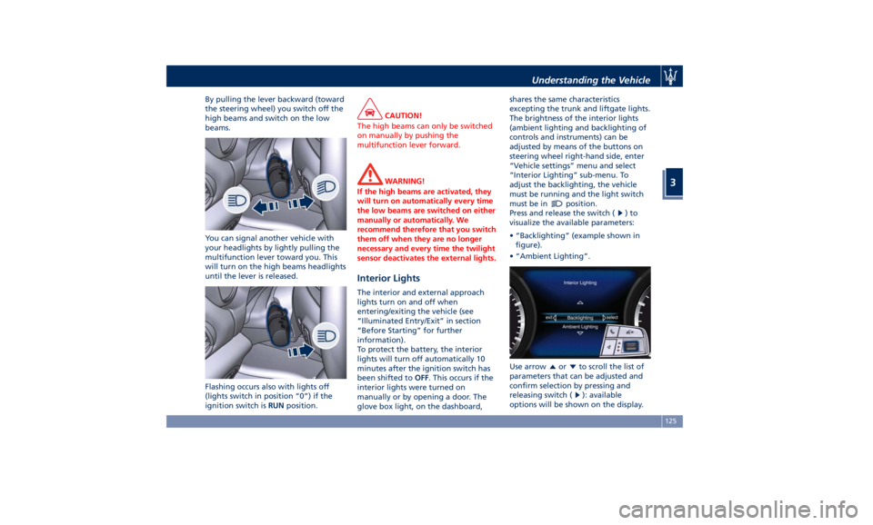
By pulling the lever backward (toward
the steering wheel) you switch off the
high beams and switch on the low
beams.
You can signal another vehicle with
your headlights by lightly pulling the
multifunction lever toward you. This
will turn on the high beams headlights
until the lever is released.
Flashing occurs also with lights off
(lights switch in position “0”) if the
ignition switch is RUN position. CAUTION!
The high beams can only be switched
on manually by pushing the
multifunction lever forward.
WARNING!
If the high beams are activated, they
will turn on automatically every time
the low beams are switched on either
manually or automatically. We
recommend therefore that you switch
them off when they are no longer
necessary and every time the twilight
sensor deactivates the external lights.
Interior Lights The interior and external approach
lights turn on and off when
entering/exiting the vehicle (see
“Illuminated Entry/Exit” in section
“Before Starting” for further
information).
To protect the battery, the interior
lights will turn off automatically 10
minutes after the ignition switch has
been shifted to OFF . This occurs if the
interior lights were turned on
manually or by opening a door. The
glove box light, on the dashboard, shares the same characteristics
excepting the trunk and liftgate lights.
The brightness of the interior lights
(ambient lighting and backlighting of
controls and instruments) can be
adjusted by means of the buttons on
steering wheel right-hand side, enter
“Vehicle settings” menu and select
“Interior Lighting” sub-menu. To
adjust the backlighting, the vehicle
must be running and the light switch
must be in
position.
Press and release the switch (
)to
visualize the available parameters:
• “Backlighting” (example shown in
figure).
• “Ambient Lighting”.
Use arrow
or to scroll the list of
parameters that can be adjusted and
confirm selection by pressing and
releasing switch (
): available
options will be shown on the display.Understanding the Vehicle
3
125
Page 132 of 436
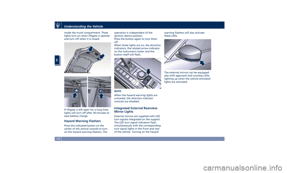
inside the trunk compartment. These
lights turn on when liftgate is opened
and turn off when it is closed.
If liftgate is left open for a long time,
lights will turn off after 30 minutes to
save battery charge.
Hazard Warning Flashers Press the indicated button on the
center of the central console to turn
on the hazard warning flashers. The operation is independent of the
ignition device position.
Press the button again to turn them
off.
When these lights are on, the direction
indicators, the related arrow indicator
on the instrument cluster and the
button itself will flash.
NOTE:
When the hazard warning lights are
activated, the direction indicator
controls are disabled.
Integrated External Rearview
Mirror Lights External mirrors are supplied with LED
turn signals integrated on the support.
The LED turn signal indicators flash
simultaneously with the corresponding
turn signal lights in the front and rear
of the vehicle. Turning on the hazard warning flashers will also activate
these LEDs.
The external mirrors can be equipped
also with approach and courtesy LEDs,
lighting up when the vehicle entry/exit
lights are activated.Understanding the Vehicle
3
128
Page 137 of 436

Interior Features Electric Power Outlets The vehicle is equipped with four 12
Volt (13 Amp) electric power outlets,
two available for the front seat
passengers, one for rear seat
passengers and one fitted in the trunk
compartment.
In vehicles equipped with “Smoking
Kit” the electric power outlet inside
the cupholder is replaced with a
cigarette lighter.
All power outlets are supplied only
when the engine is started or the
ignition device set to ACC or RUN .
Power outlets are protected by a fuse.
Insert a cigar lighter or accessory plug
into the power outlets to ensure
proper operation. Otherwise, check
the matching fuse integrity, see “Fuse
Replacement” in section
“Maintenance and Care” for further
information.
CAUTION!
• Do not plug in accessories that
exceed the maximum power of 160
Watts (13 Amps) at 12 Volts.
• Power outlets are designed for
accessory plugs only. Do not insert any other object in the power
outlets as this will damage the outlet
and blow the fuse. Damages caused
by improper use of the power outlet
are not covered by the New Vehicle
Limited Warranty.
WARNING!
To avoid serious injury or death:
• Only devices designed for use in this
type of outlet should be inserted
into any 12 Volt outlet.
• Replacing the fuses that protect
power outlets with others of higher
amperage, there is the risk of fire.
• Do not touch with wet hands.
• Close the lids when the plug is not
used and while driving the vehicle.
• If this outlet is mishandled, it may
cause an electric shock and failure.
Power Outlet inside the Cupholder
Compartment
To access the power outlet inside the
cupholder beside the shift lever, press
the cover as indicated to open it
completely. Remove the cigarette
lighter and use its socket as power
outlet. WARNING!
High power consumption items
plugged into this outlet for long
periods may discharge the battery
and/or prevent the engine from
starting.Understanding the Vehicle
3
133
Page 153 of 436
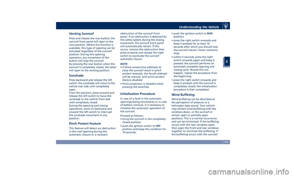
Venting Sunroof Press and release the rear button; the
sunroof front panel will open to the
vent position. Where this function is
available, this type of opening can be
activated regardless of the sunroof
position. During this opening
operation, any movement of the
button will stop the sunroof.
By pressing the rear button when the
sunroof is completely closed, the latter
will open to the venting position.
Sunshade Press backward and release the left
switch: the sunshade will move to the
vehicle rear side until completely
open.
From this position, press onward and
release the left switch to move the
sunshade to the vehicle front side
until completely closed.
During the opening and closing
operations, work on backward and
onward the left switch to interrupt
the sunshade movement in any
position.
Pinch Protect Feature This feature will detect an obstruction
in the roof opening during the
automatic closure or a constant obstruction of the sunroof front
panel. If an obstruction is detected by
the safety system during the closing
movement, the sunroof front panel
will automatically retract. If this
occurs, remove the obstruction then
press onwards and release the right
switch to reactivate the sunroof
automatic closure.
NOTE:
• If three consecutive attempts to
close the sunroof result in pinch
protect reversals, the fourth attempt
will be manual, with pinch protect
feature disabled.
• Pinch protection is disabled while
pressing the switch/es.
Initialization Procedure In case of a fault in the automatic
opening/closing movements or in case
of battery removal, it is necessary to
initialize the automatic operation of
the sunroof.
Proceed as follows:
• bring the sunroof in the completely
closed position;
• push the ignition switch to OFF
position and keep this condition for
10 seconds; • push the ignition switch to RUN
position;
• press the right switch onwards and
keep it pressed for at least 10
seconds after which you should hear
the sunroof electric motor mechanic
stop;
• within 5 seconds, press the right
switch onwards again and keep it
pressed: the sunroof performs an
automatic complete opening and
closing cycle. Should this not
happen, repeat the procedure from
the beginning;
• press the right switch onwards and
keep it pressed until the sunroof is
completely closed: the initialization
procedure is then completed.
Wind Buffeting Wind buffeting can be described as
the perception of pressure or a
helicopter-type sound. Your vehicle
may exhibit wind buffeting with the
windows down, or the sunroof in
certain open or partially open
positions. This is a normal occurrence
and can be minimized. If the buffeting
occurs with the rear windows open,
then open the front and rear windows
together to minimize the buffeting. If
the buffeting occurs with the sunroofUnderstanding the Vehicle
3
149
Page 154 of 436
open, then adjust the sunroof opening
to minimize the buffeting.
Ignition Off Operation The power sunroof controls will
remain active for up to approximately
ten minutes after the ignition switch is
in OFF position. Opening either front
door will cancel this feature. The
ignition system timing can be set using
the MTC+ System (see “MTC+ Settings”
in section “Dashboard Instruments and
Controls”).
Sunroof Maintenance Use only a nonabrasive cleaner and a
soft cloth to clean the glass panel. HomeLink ®
(optional) HomeLink ®
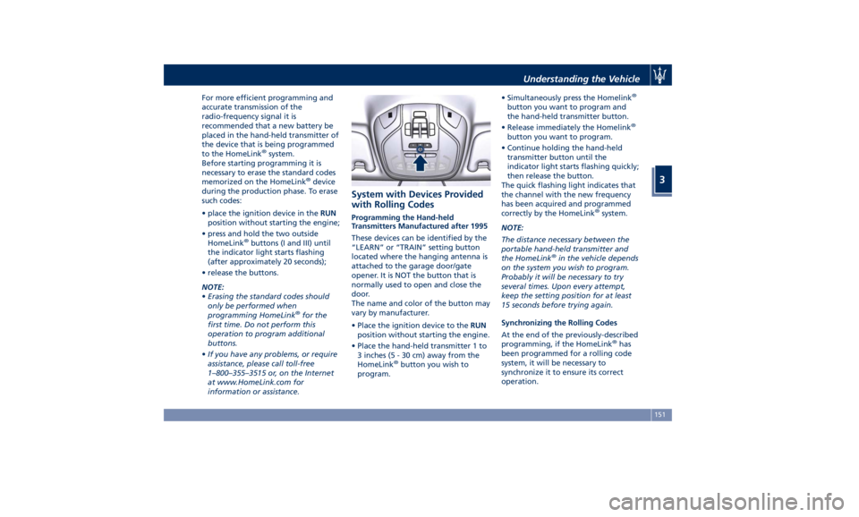
replaces up to three
hand-held transmitters operating the
automatic devices that open garage
doors and gates, enable/disable the
lighting or security systems. The
HomeLink ®
unit is powered by your
vehicle's 12 Volt battery. The
HomeLink ®
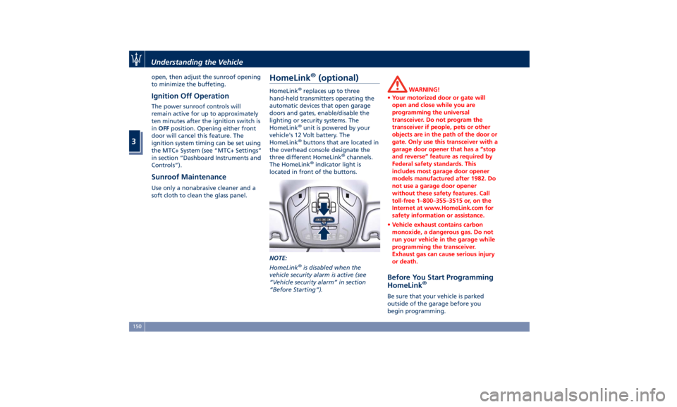
buttons that are located in
the overhead console designate the
three different HomeLink ®
channels.
The HomeLink ®
indicator light is
located in front of the buttons.
NOTE:
HomeLink ®
is disabled when the
vehicle security alarm is active (see
“Vehicle security alarm” in section
“Before Starting”). WARNING!
• Your motorized door or gate will
open and close while you are
programming the universal
transceiver. Do not program the
transceiver if people, pets or other
objects are in the path of the door or
gate. Only use this transceiver with a
garage door opener that has a “stop
and reverse” feature as required by
Federal safety standards. This
includes most garage door opener
models manufactured after 1982. Do
not use a garage door opener
without these safety features. Call
toll-free 1–800–355–3515 or, on the
Internet at www.HomeLink.com for
safety information or assistance.
• Vehicle exhaust contains carbon
monoxide, a dangerous gas. Do not
run your vehicle in the garage while
programming the transceiver.
Exhaust gas can cause serious injury
or death.
Before You Start Programming
HomeLink ®
Be sure that your vehicle is parked
outside of the garage before you
begin programming.Understanding the Vehicle
3
150
Page 155 of 436
For more efficient programming and
accurate transmission of the
radio-frequency signal it is
recommended that a new battery be
placed in the hand-held transmitter of
the device that is being programmed
to the HomeLink ®
system.
Before starting programming it is
necessary to erase the standard codes
memorized on the HomeLink ®
device
during the production phase. To erase
such codes:
• place the ignition device in the RUN
position without starting the engine;
• press and hold the two outside
HomeLink ®
buttons (I and III) until
the indicator light starts flashing
(after approximately 20 seconds);
• release the buttons.
NOTE:
• Erasing the standard codes should
only be performed when
programming HomeLink ®
for the
first time. Do not perform this
operation to program additional
buttons.
• If you have any problems, or require
assistance, please call toll-free
1–800–355–3515 or, on the Internet
at www.HomeLink.com for
information or assistance. System with Devices Provided
with Rolling Codes Programming the Hand-held
Transmitters Manufactured after 1995
These devices can be identified by the
“LEARN” or “TRAIN” setting button
located where the hanging antenna is
attached to the garage door/gate
opener. It is NOT the button that is
normally used to open and close the
door.
The name and color of the button may
vary by manufacturer.
• Place the ignition device to the RUN
position without starting the engine.
• Place the hand-held transmitter 1 to
3 inches (5 - 30 cm) away from the
HomeLink ®
button you wish to
program. • Simultaneously press the Homelink ®
button you want to program and
the hand-held transmitter button.
• Release immediately the Homelink ®
button you want to program.
• Continue holding the hand-held
transmitter button until the
indicator light starts flashing quickly;
then release the button.
The quick flashing light indicates that
the channel with the new frequency
has been acquired and programmed
correctly by the HomeLink ®
system.
NOTE:
The distance necessary between the
portable hand-held transmitter and
the HomeLink ®
in the vehicle depends
on the system you wish to program.
Probably it will be necessary to try
several times. Upon every attempt,
keep the setting position for at least
15 seconds before trying again.
Synchronizing the Rolling Codes
At the end of the previously-described
programming, if the HomeLink ®
has
been programmed for a rolling code
system, it will be necessary to
synchronize it to ensure its correct
operation.Understanding the Vehicle
3
151