2019 MASERATI GRANTURISMO CONVERTIBLE stop start
[x] Cancel search: stop startPage 68 of 296
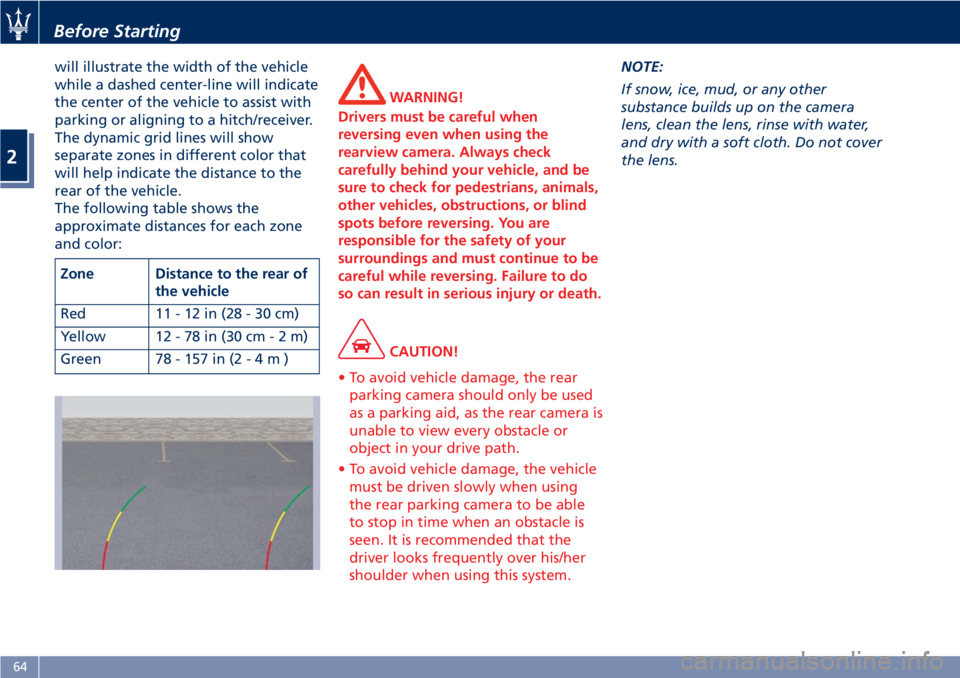
will illustrate the width of the vehicle
while a dashed center-line will indicate
the center of the vehicle to assist with
parking or aligning to a hitch/receiver.
The dynamic grid lines will show
separate zones in different color that
will help indicate the distance to the
rear of the vehicle.
The following table shows the
approximate distances for each zone
and color:
Zone Distance to the rear of
the vehicle
Red 11-12in(28-30cm)
Yellow 12 - 78 in (30 c m-2m)
Green 78 - 157 in ( 2-4m) WARNING!
Drivers must be careful when
reversing even when using the
rearview camera. Always check
carefully behind your vehicle, and be
sure to check for pedestrians, animals,
other vehicles, obstructions, or blind
spots before reversing. You are
responsible for the safety of your
surroundings and must continue to be
careful while reversing. Failure to do
so can result in serious injury or death.
CAUTION!
• To avoid vehicle damage, the rear
parking camera should only be used
as a parking aid, as the rear camera is
unable to view every obstacle or
object in your drive path.
• To avoid vehicle damage, the vehicle
must be driven slowly when using
the rear parking camera to be able
to stop in time when an obstacle is
seen. It is recommended that the
driver looks frequently over his/her
shoulder when using this system. NOTE:
If
snow, ice, mud, or any other
substance builds up on the camera
lens, clean the lens, rinse with water,
and dry with a soft cloth. Do not cover
the lens.Before Starting
2
64
Page 78 of 296
Front Seats Seats and seat belts are part of the
Occupant Restraint System of the
vehicle. For further information, see
chapter “Occupant Restraint System”
in Section “Before Starting”.
WARNING!
Be sure everyone in your vehicle is in a
seat and using a seat belt properly.
Seat Adjustments The seats can only be adjusted with
the key in the ignition switch in MAR
(ON) position.
It is however possible, when the door
is closed, to operate the seat for
approx. 15 seconds after turning the
key to STOP (OFF) position and then
for other 15 seconds after the last
operation.
The power seats switches are located
on the outboard side of the seat
cushion.
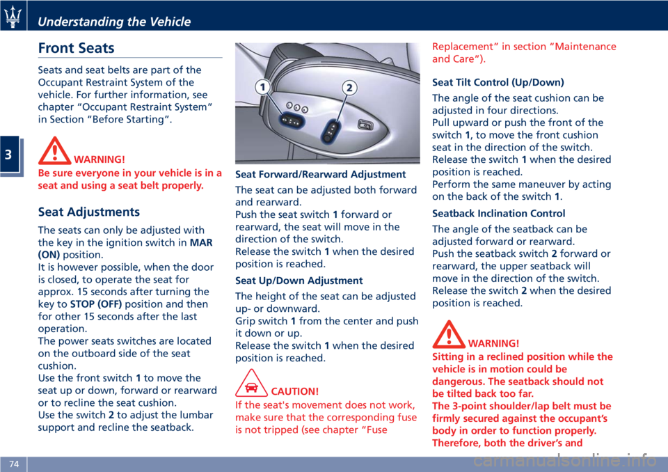
Use the front switch 1 to move the
seat up or down, forward or rearward
or to recline the seat cushion.
Use the switch 2 to adjust the lumbar
support and recline the seatback. Seat Forward/Rearward Adjustment
The seat can be adjusted both forward
and rearward.
Push the seat switch 1 forward or
rearward, the seat will move in the
direction of the switch.
Release the switch 1 when the desired
position is reached.
Seat Up/Down Adjustment
The height of the seat can be adjusted
up- or downward.
Grip switch 1 from the center and push
it down or up.
Release the switch 1 when the desired
position is reached.
CAUTION!
If the seat's movement does not work,
make sure that the corresponding fuse
is not tripped (see chapter “Fuse Replacement” in section “Maintenance
and Care”).
Seat Tilt Control (Up/Down)
The
angle of the seat cushion can be
adjusted in four directions.
Pull upward or push the front of the
switch 1 , to move the front cushion
seat in the direction of the switch.
Release the switch 1 when the desired
position is reached.
Perform the same maneuver by acting
on the back of the switch 1 .
Seatback Inclination Control
The angle of the seatback can be
adjusted forward or rearward.
Push the seatback switch 2 forward or
rearward, the upper seatback will
move in the direction of the switch.
Release the switch 2 when the desired
position is reached.
WARNING!
Sitting in a reclined position while the
vehicle is in motion could be
dangerous. The seatback should not
be tilted back too far.
The 3-point shoulder/lap belt must be
firmly secured against the occupant’s
body in order to function properly.
Therefore, both the driver’s andUnderstanding the Vehicle
3
74
Page 82 of 296
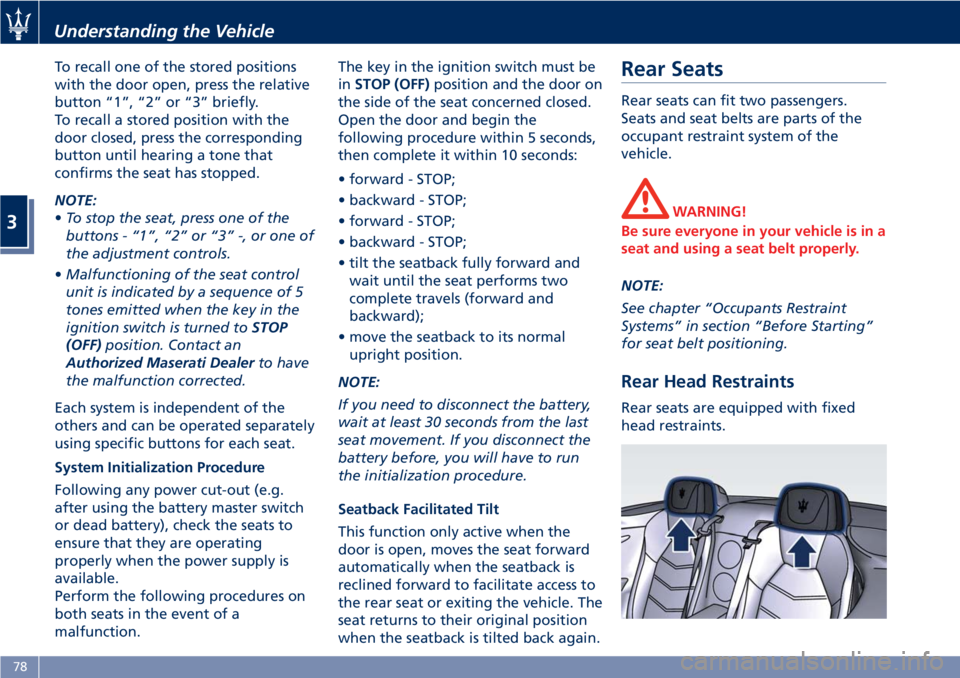
To recall one of the stored positions
with the door open, press the relative
button “1”, “2” or “3” briefly.
To recall a stored position with the
door closed, press the corresponding
button until hearing a tone that
confirms the seat has stopped.
NOTE:
• To stop the seat, press one of the
buttons - “1”, “2” or “3” -, or one of
the adjustment controls.
• Malfunctioning of the seat control
unit is indicated by a sequence of 5
tones emitted when the key in the
ignition switch is turned to STOP
(OFF) position. Contact an
Authorized Maserati Dealer to have
the malfunction corrected.
Each system is independent of the
others and can be operated separately
using specific buttons for each seat.
System Initialization Procedure
Following any power cut-out (e.g.
after using the battery master switch
or dead battery), check the seats to
ensure that they are operating
properly when the power supply is
available.
Perform the following procedures on
both seats in the event of a
malfunction. The key in the ignition switch must be
in STOP (OFF) position and the door on
the side of the seat concerned closed.
Open the door and begin the
following procedure within 5 seconds,
then complete it within 10 seconds:
• forward - STOP;
• backward - STOP;
• forward - STOP;
• backward - STOP;
• tilt the seatback fully forward and
wait until the seat performs two
complete travels (forward and
backward);
• move the seatback to its normal
upright position.
NOTE:
If you need to disconnect the battery,
wait at least 30 seconds from the last
seat movement. If you disconnect the
battery before, you will have to run
the initialization procedure.
Seatback Facilitated Tilt
This function only active when the
door is open, moves the seat forward
automatically when the seatback is
reclined forward to facilitate access to
the rear seat or exiting the vehicle. The
seat returns to their original position
when the seatback is tilted back again. Rear Seats Rear seats can fit two passengers.
Seats and seat belts are parts of the
occupant restraint system of the
vehicle.
WARNING!
Be sure everyone in your vehicle is in a
seat and using a seat belt properly.
NOTE:
See
chapter “Occupants Restraint
Systems” in section “Before Starting”
for seat belt positioning.
Rear Head Restraints Rear seats are equipped with fixed
head restraints.Understanding the Vehicle
3
78
Page 94 of 296

(Continued)
damaged if the wiper control is left
in any position other than “OFF”.
• In cold weather, always turn off the
wiper switch and allow the wipers to
return to the park position before
turning off the engine. If the wiper
switch is left on and the wipers
freeze to the windshield, the wiper
motor may be damaged when the
vehicle is restarted.
• Always remove any buildup of snow
that prevents the windshield wiper
blades from returning to the off
position. If the windshield wiper
control is turned off and the blades
cannot return to the off position, the
wiper motor may be damaged.
Rain Sensing Wipers This feature detects moisture on the
windshield through an inside rearview
mirror integrated sensor.
The rain sensor adapts the frequency
of the windshield wiper strokes (in the
intermittent operation mode) to the
intensity of the rain.
All the other functions controlled by
the right-hand multifunction lever
(windshield wipers off, in continuous
slow and fast operation mode and in temporary fast operation mode)
remain the same.
The rain sensor is activated
automatically by moving the
right-hand multifunction lever to
"AUTO" position. The sensor has a
setting range that varies progressively:
from the windshield wiper stationary
position - when the windshield is dry -
to the windshield wiper second speed -
in conditions of pouring rain.
To regulate the frequency of
intermittent operation, with the
right-hand multifunction lever in
"AUTO" position, turn the end section
of the lever.
Rotating the end section clockwise,
intermittent operation varies from fast
intermittent wipe (max.) to slow
intermittent wipe (min).
If the engine is turned off during
automatic windshield wiper operation, with the right-hand multifunction
lever in "AUTO" position, to reactivate
the function the next time the engine
is started, the lever must be moved to
"OFF" (stop position) then back to
"AUTO" position.
CAUTION!
• The rain sensing feature may not
function properly by ice or dried salt
water on the windshield.
• Use on the windshield of RainX ®
or
products containing wax or silicone
may reduce rain sensor performance.
Rain Sensor Failure
When
the rain sensor is activated, in
the event that it is malfunctioning, the
windshield wiper will be switched on
in intermittent operation mode and
the sensing range will be set by the
user, regardless of whether or not
there is rain on the windshield.
The
symbol appears on the
instrument cluster display.
In this case, we recommend that you
cut-out the rain sensor and turn on the
wiper, if necessary, in continuous
mode. Contact the Authorized
Maserati Dealer as soon as possible.Understanding the Vehicle
3
90
Page 96 of 296
Soft Top NOTE:
By soft top “opening” we
mean folding the soft top
into the rear luggage
compartment.
By soft top “closing” we
mean the opposite.
Precautions Before and during the soft top
operation observe the following
precautions.
WARNING!
• Before opening or closing the soft
top, always check that no one is in
the way, as impact with the soft top
may cause injury. Also check that no
objects stand in the way of the soft
top, as impact may cause damage to
both the soft top and the object.
• The movement of the soft top with
the engine running must be
performed outdoor. Exhaust gases
contain carbon monoxide which is
strongly toxic and potentially lethal. • In case of hazard, release the soft
top button, which stops its
movement.
• Keep your hands away from the soft
top levers, the soft top compartment
and the upper edge of the
windshield.
• Before operating the soft top, make
sure that no passengers are sitting in
the rear seats.
• Never operate or act on a soft top
that is performing an automatic
movement cycle.
CAUTION!
• Do not open the soft top when it is
wet, as the damp that would form in
the soft top housing might cause
permanent damage to the structure
or stains or mold in the canvas.
Should it need to be opened, do not
leave it sitting in the housing for
more than a day.
• Open the soft top when it is dirty, as
both the canvas and the rear window
might be damaged when it is folded.
• Do not open the soft top if there is
ice or snow on it. Should it need to
be opened, remove the snow or ice and do not use sharp or pointed
objects.
• Do not place objects on the soft top
as they might fall and cause damage
and injury when it is moved.
• Do not place any objects in the soft
top housing.
• Do not fasten roof-racks or similar on
the soft top.
• When closing the soft top, never
start driving before the soft top has
completed the closing cycle and has
locked on the windshield frame.
• Only open or close the soft top when
the vehicle is stationary, otherwise it
might not fully open or close. For
example, if you start moving the soft
top when you are standing at a
traffic light and you start driving
before the soft top has completed its
opening or closing cycle, you can
complete the operation by driving
slowly (do not exceed 19 mph -
30 km/h) and holding the soft top
movement switch pushed until the
process has been completed.
• If you are driving at high speeds,
vacuum might be created in the
passenger compartment and the soft
top might start “wobbling”; to solveUnderstanding the Vehicle
3
92
Page 102 of 296
NOTE:
The soft top failure temporarily
disables, for approx. 10 minutes, the
power windows’ operation. After this
time, the power windows will resume
normal functioning.
Soft Top Manual Closing
Operation In case of need, the soft top may be
closed manually.
WARNING!
• Manual operation of the soft top for
emergency closing requires the
presence of two persons in order to
prevent personal injury or damage
to the car.
• When moving the soft top by hand,
take the greatest care as its movable
parts could squeeze or trap objects
or parts of your body.
CAUTION!
The emergency procedure described
below must be used to close the soft
top if it is not possible for you to
contact the Authorized Maserati
Dealer immediately and you cannot
keep the soft top open. If the failure occurs when the opening
procedure
is already in progress, do
not attempt to complete the
procedure - close back the soft top
manually according to the following
instructions. After depressurizing the
hydraulic circuit by turning the key in
the ignition switch to STOP (OFF)
position, perform the emergency
procedure starting from the point at
which the opening stage jammed.
WARNING!
After depressurizing the system, the
soft top will move freely. Therefore, if
it is not in a balanced position, it will
close or open as a consequence of its
weight. Take the greatest care to
avoid being squeezed or trapped by
its levers and mechanisms.
Before Starting
NOTE:
• During
emergency closing, the side
windows must be lowered.
•
To move the soft top manually, you
must depressurize the hydraulic system
by turning the key in the ignition
switch to
STOP (OFF) position and
waiting approx. 10 minutes. • To avoid unintentional activations,
we recommend that you remove the
key from the ignition switch. Take
the flat-head screwdriver and the
wrench to lock/unlock the soft top
hinges out of the tool kit located in
the trunk compartment (see "Tool
Kit" in section "In an Emergency").
Soft Top Closing
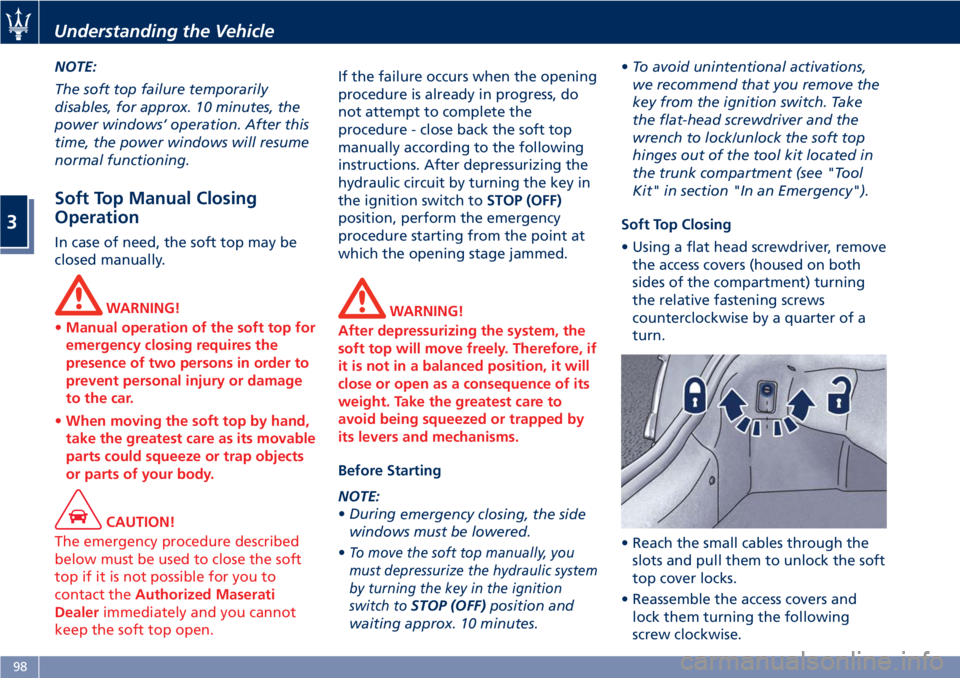
• Using a flat head screwdriver, remove
the access covers (housed on both
sides of the compartment) turning
the relative fastening screws
counterclockwise by a quarter of a
turn.
• Reach the small cables through the
slots and pull them to unlock the soft
top cover locks.
• Reassemble the access covers and
lock them turning the following
screw clockwise.Understanding the Vehicle
3
98
Page 106 of 296
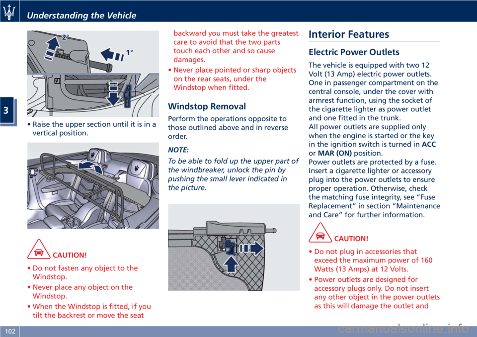
• Raise the upper section until it is in a
vertical position.
CAUTION!
• Do not fasten any object to the
Windstop.
• Never place any object on the
Windstop.
• When the Windstop is fitted, if you
tilt the backrest or move the seat backward you must take the greatest
care to avoid that the two parts
touch each other and so cause
damages.
• Never place pointed or sharp objects
on the rear seats, under the
Windstop when fitted.
Windstop Removal Perform the operations opposite to
those outlined above and in reverse
order.
NOTE:
To be able to fold up the upper part of
the windbreaker, unlock the pin by
pushing the small lever indicated in
the picture. Interior Features Electric Power Outlets The vehicle is equipped with two 12
Volt (13 Amp) electric power outlets.
One in passenger compartment on the
central console, under the cover with
armrest function, using the socket of
the cigarette lighter as power outlet
and one fitted in the trunk.
All power outlets are supplied only
when the engine is started or the key
in the ignition switch is turned in ACC
or MAR (ON) position.
Power outlets are protected by a fuse.
Insert a cigarette lighter or accessory
plug into the power outlets to ensure
proper operation. Otherwise, check
the matching fuse integrity, see “Fuse
Replacement” in section “Maintenance
and Care” for further information.
CAUTION!
• Do not plug in accessories that
exceed the maximum power of 160
Watts (13 Amps) at 12 Volts.
• Power outlets are designed for
accessory plugs only. Do not insert
any other object in the power outlets
as this will damage the outlet andUnderstanding the Vehicle
3
102
Page 113 of 296
WARNING!
Vehicle exhaust contains carbon
monoxide, a dangerous gas. Do not
run your vehicle in the garage while
programming the transceiver. Exhaust
gas can cause serious injury or death.
Customer Service If you have problems with training the
HomeLink Universal Transceiver, or
would like information on home
products that can be operated by the
transmitter, call (800) 355-3515. On the
Internet, go to www.Homelink.com.
Safety Precautions Always refer to the operating
instructions and safety information
that came with your garage door
opener or other equipment you
intend to operate with the HomeLink
Universal Transceiver. If you do not
have this information, you should
contact the manufacturer of the
equipment.
While training or using HomeLink,
make sure you have a clear view of
the garage door or gate, and that no
one will be injured by its movement. General Information While programming HomeLink ®
,itis
advisable to disconnect the drive
motor of the gate/door to be remote
controlled, since the numerous driving
pulses launched for this operation
might damage it.
If the battery fails or is disconnected,
the stored settings are not deleted.
If the gate/door was manufactured
prior to April 1982 (not equipped with
safety systems or automatic stop in the
event of an obstacle in the range of
action), the gate/door cannot be
controlled by HomeLink ®
.
If you have questions, call (800)
355-3515.
WARNING!
California Proposition 65
Operating, servicing and maintaining
a passenger vehicle or off-road vehicle
can expose you to chemicals including
such as, engine exhaust, carbon
monoxide, phthalates and lead, that
which are know to the State of
California to cause cancer and birth
defects or other reproductive harm. To
minimize exposure, avoid breathing
exhaust, do not idle the engine except
as necessary, service your vehicle in a well-ventilated area and wear gloves
or wash your hands frequently when
servicing your vehicle. For more
information go to:
www.P65Warnings.ca.gov/passenger-
vehicle
Programming • Press and hold buttons "1" and "3".
• After about 20 seconds, the LED
starts flashing.
• Release the buttons.
• Hold the remote control for the
device to be controlled close to the
HomeLink ®
control panel (0-30 cm/
0-12 in).
• Simultaneously press and hold the
button on the hand-held remote
control and one of the three
HomeLink ®
buttons "1", "2" or "3".
• Successful programming is signaled
by the LED flashing faster.
• Release the buttons.
To program the other buttons, repeat
the operations skipping the first three
steps.Understanding the Vehicle
3
109