2019 HYUNDAI SONATA HYBRID ECO mode
[x] Cancel search: ECO modePage 14 of 546
H3
PPHH EEVV (( PP LLUU GG--IINN EE LLEE CCTT RR IICC VV EEHH IICC LLEE )) SS YY SSTT EEMM
Plug-in Hybrid Vehicle
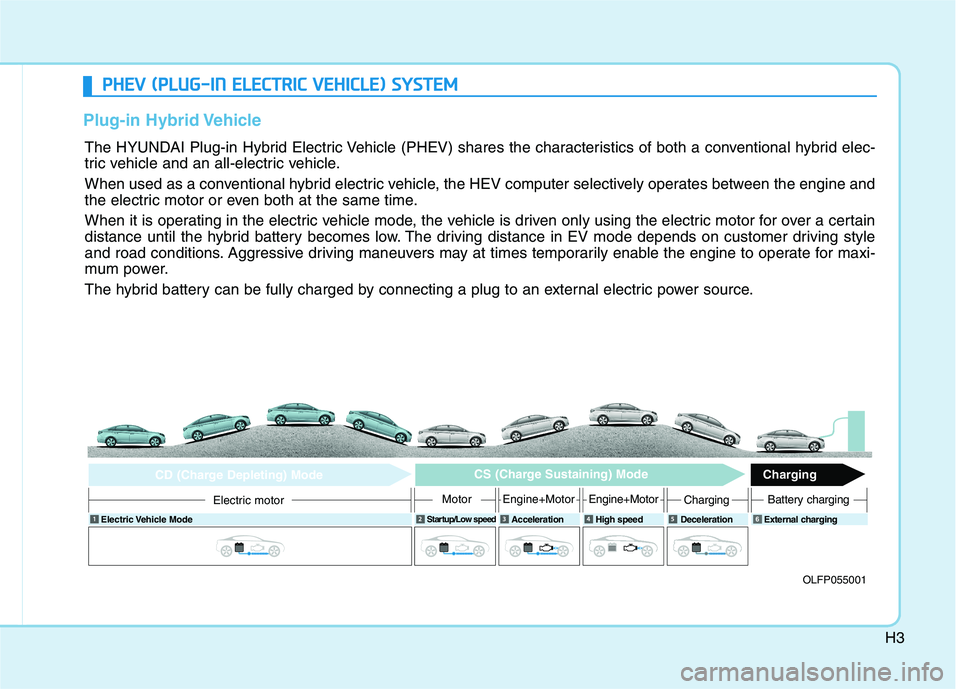
The HYUNDAI Plug-in Hybrid Electric Vehicle (PHEV) shares the characteristics of both a conventional hybrid elec-
tric vehicle and an all-electric vehicle.
When used as a conventional hybrid electric vehicle, the HEV computer selectively operates between the engine and
the electric motor or even both at the same time.
When it is operating in the electric vehicle mode, the vehicle is driven only using the electric motor for over a certain
distance until the hybrid battery becomes low. The driving distance in EV mode depends on customer driving style
and road conditions. Aggressive driving maneuvers may at times temporarily enable the engine to operate for maxi-
mum power.
The hybrid battery can be fully charged by connecting a plug to an external electric power source.
OLFP055001
Electric Vehicle Mode
Startup/Low speed
Acceleration High speed Deceleration External charging
Electric motor
CD (Charge Depleting) Mode CS (Charge Sustaining) Mode
Charging
MotorEngine+MotorEngine+MotorChargingBattery charging
6
Page 33 of 546
H22
DDRRIIVV IINN GG TT HH EE HH YY BBRRIIDD //PP LLUU GG--IINN HH YY BBRRIIDD VV EEHH IICC LLEE
Starting the vehicle
1. Carry the smart key or leave it
inside the vehicle.
2. Make sure the parking brake is firmly applied.
3. Place the shift lever in P (Park). With the shift lever in N (Neutral),
you cannot start the vehicle.
4. Depress the brake pedal.
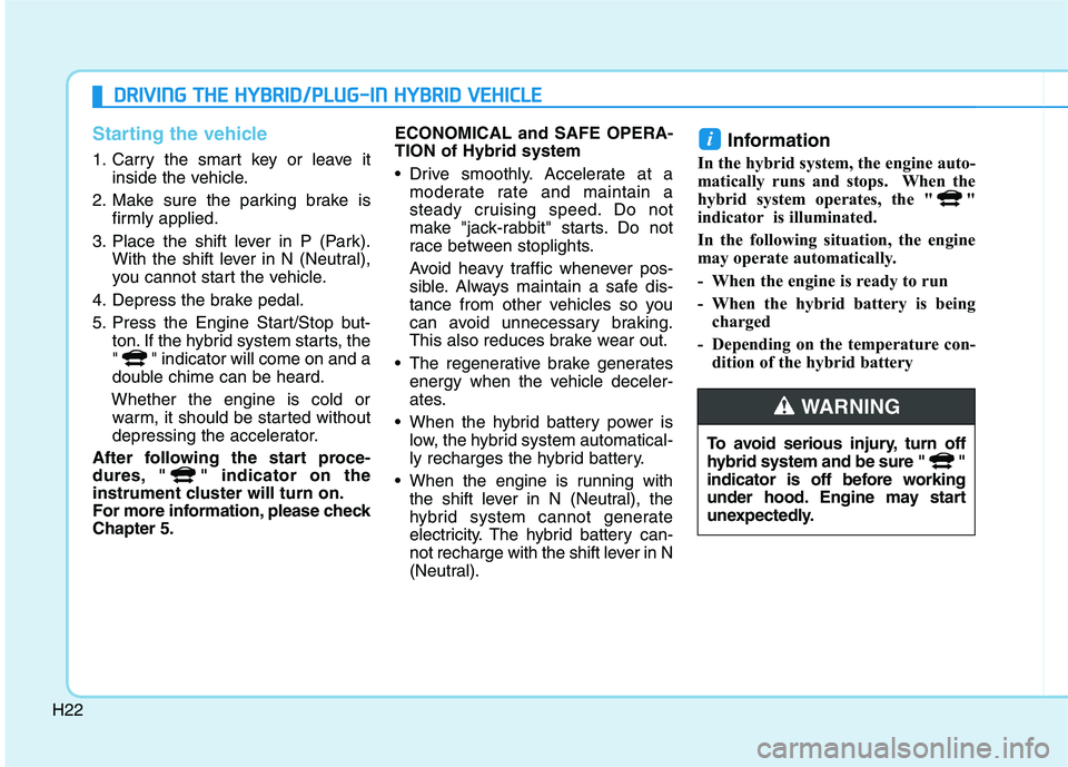
5. Press the Engine Start/Stop but- ton. If the hybrid system starts, the
" " indicator will come on and a
double chime can be heard.
Whether the engine is cold or warm, it should be started without
depressing the accelerator.
After following the start proce-
dures, " " indicator on the
instrument cluster will turn on.
For more information, please checkChapter 5. ECONOMICAL and SAFE OPERA- TION of Hybrid system
Drive smoothly. Accelerate at a
moderate rate and maintain a
steady cruising speed. Do not
make "jack-rabbit" starts. Do not
race between stoplights.
Avoid heavy traffic whenever pos-
sible. Always maintain a safe dis-
tance from other vehicles so you
can avoid unnecessary braking.
This also reduces brake wear out.
The regenerative brake generates energy when the vehicle deceler-
ates.
When the hybrid battery power is low, the hybrid system automatical-
ly recharges the hybrid battery.
When the engine is running with the shift lever in N (Neutral), the
hybrid system cannot generate
electricity. The hybrid battery can-
not recharge with the shift lever in N
(Neutral). Information
In the hybrid system, the engine auto-
matically runs and stops. When the
hybrid system operates, the " "
indicator is illuminated.
In the following situation, the engine
may operate automatically.
- When the engine is ready to run
- When the hybrid battery is being charged
- Depending on the temperature con- dition of the hybrid battery
i
To avoid serious injury, turn off
hybrid system and be sure " "
indicator is off before working
under hood. Engine may start
unexpectedly.
WARNING
Page 36 of 546

H25
CHARGE :Shows that the energy made bythe vehicle is being converted
to electrical energy. (Regeneratedenergy)
ECO :
Shows that the vehicle is beingdriven in an Eco-friendly manner.
POWER : Shows that the vehicle is exceeding
the Eco-friendly range.
According to the hybrid systemgauge area, the "EV" indicator comes
on or off.
- "EV" indicator ON : Vehicle is driven using the electric motor or thegasoline engine is stopped.
- "EV" indicator OFF : Vehicle is driv- en using the gasoline engine.Hybrid Battery SOC
(State of Charge) Gauge
This gauge indicates the remaining
hybrid battery power. If the SOC is
near the "L (Low)" level, the vehicle
automatically operates the engine to
charge the battery. However, if the Service Indicator ( ) and Malfunction Indicator Lamp (MIL)
( ) turn on when the SOC (State of
charge) gauge is near the "L (Low)"
level, have the vehicle checked by an
authorized HYUNDAI dealer.
OLFH047105
OLFPQ047105K
■
Plug-in hybrid model vehicles only
■ Hybrid model vehicles only
Page 38 of 546
H27
Warning and indicator lights
Ready Indicator
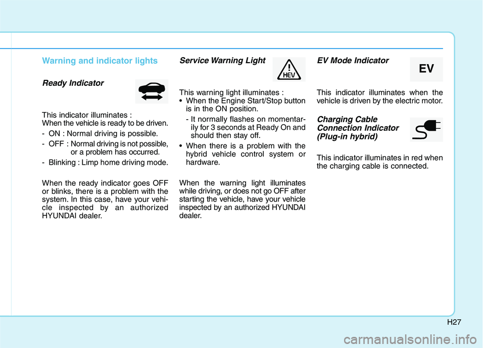
This indicator illuminates :
When the vehicle is ready to be driven.
- ON : Normal driving is possible.
- OFF : Normal driving is not possible,
or a problem has occurred.
- Blinking : Limp home driving mode. When the ready indicator goes OFF
or blinks, there is a problem with the
system. In this case, have your vehi-
cle inspected by an authorized
HYUNDAI dealer.
Service Warning Light
This warning light illuminates :
When the Engine Start/Stop button is in the ON position.
- It normally flashes on momentar-ily for 3 seconds at Ready On and
should then stay off.
When there is a problem with the hybrid vehicle control system or
hardware.
When the warning light illuminates
while driving, or does not go OFF after
starting the vehicle, have your vehicle
inspected by an authorized HYUNDAI
dealer.
EV Mode Indicator
This indicator illuminates when the
vehicle is driven by the electric motor.
Charging Cable Connection Indicator (Plug-in hybrid)
This indicator illuminates in red when
the charging cable is connected.
EV
Page 43 of 546
H32
DDRRIIVV IINN GG TT HH EE HH YY BBRRIIDD //PP LLUU GG--IINN HH YY BBRRIIDD VV EEHH IICC LLEE (( CC OO NNTT..))
❈ Example of a deceleration event is
going down an extended hill, slow-
ing down approaching a toll booth,and approaching reduced speed
zones.
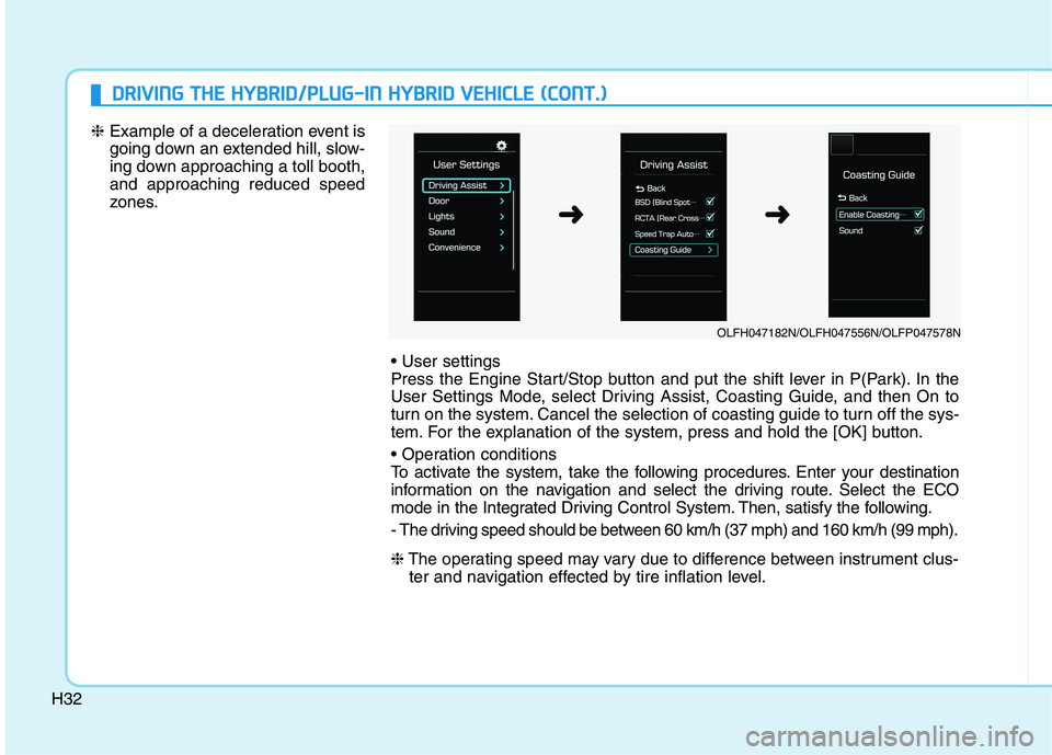
Press the Engine Start/Stop button and put the shift lever in P(Park). In the
User Settings Mode, select Driving Assist, Coasting Guide, and then On to
turn on the system. Cancel the selection of coasting guide to turn off the sys-
tem. For the explanation of the system, press and hold the [OK] button.
To activate the system, take the following procedures. Enter your destination
information on the navigation and select the driving route. Select the ECO
mode in the Integrated Driving Control System. Then, satisfy the following.
- The driving speed should be between 60 km/h (37 mph) and 160 km/h (99 mph). ❈The operating speed may vary due to difference between instrument clus-
ter and navigation effected by tire inflation level.
OLFH047182N/OLFH047556N/OLFP047578N
➜➜
Page 112 of 546
2-46
Safety system of your vehicle
5. Remove as much slack from thebelt as possible by pushing down
on the child restraint system while
feeding the shoulder belt back into
the retractor.
6. Push and pull on the child restraint system to confirm that the seat
belt is holding it firmly in place. If itis not, release the seat belt andrepeat steps 2 through 6.
7. Double check that the retractor is in the "Automatic Locking" mode
by attempting to pull more of the
seat belt out of the retractor. If you
cannot, the retractor is in the
“Automatic Locking” mode.
If your CRS manufacturer instructs or
recommends you to use a tetheranchor with the lap/shoulder belt,
refer to the previous pages for more
information. When the seat belt is allowed to
retract to its fully stowed position,
the retractor will automatically
switch from the "Automatic
Locking" mode to the emergency
lock mode for normal adult usage.
To remove the child restraint, press
the release button on the buckle andthen pull the lap/shoulder belt out of
the restraint and allow the seat belt
to retract fully.NOTICE
If the retractor is not in the
"Automatic Locking" mode, the
child restraint can move when
your vehicle turns or stops sud-
denly. A child can be seriously
injured or killed if the child
restraint is not properly
anchored in the car, including
manually pulling the seat belt
all the way out to shift the rec-
tractor to the "Automatic
Locking" mode.
WARNING
Page 115 of 546
2-49
Safety system of your vehicle
2
Where Are the Air Bags?
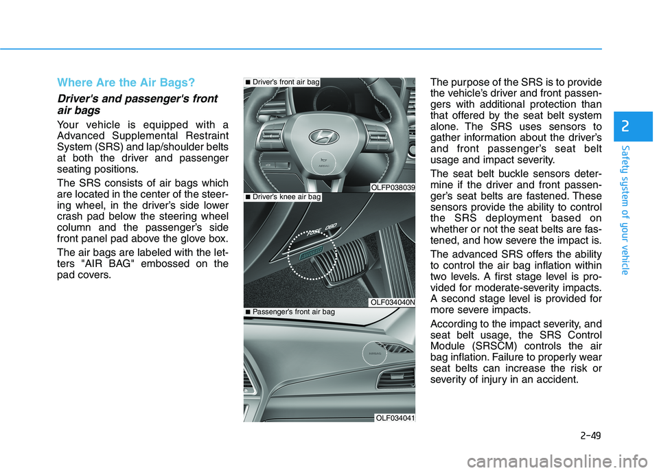
Driver's and passenger's frontair bags
Your vehicle is equipped with a
Advanced Supplemental RestraintSystem (SRS) and lap/shoulder belts
at both the driver and passenger
seating positions. The SRS consists of air bags which are located in the center of the steer-
ing wheel, in the driver’s side lower
crash pad below the steering wheel
column and the passenger’s side
front panel pad above the glove box. The air bags are labeled with the let-
ters "AIR BAG" embossed on the
pad covers. The purpose of the SRS is to provide
the vehicle’s driver and front passen-gers with additional protection than
that offered by the seat belt system
alone. The SRS uses sensors to
gather information about the driver’s
and front passenger’s seat belt
usage and impact severity.
The seat belt buckle sensors deter-
mine if the driver and front passen-
ger’s seat belts are fastened. These
sensors provide the ability to control
the SRS deployment based on
whether or not the seat belts are fas-
tened, and how severe the impact is.
The advanced SRS offers the ability to control the air bag inflation within
two levels. A first stage level is pro-
vided for moderate-severity impacts.
A second stage level is provided for
more severe impacts.
According to the impact severity, and
seat belt usage, the SRS ControlModule (SRSCM) controls the air
bag inflation. Failure to properly wear
seat belts can increase the risk or
severity of injury in an accident.
OLFP038039
OLF034040N
OLF034041
■
Driver’s knee air bag
■Driver’s front air bag
■ Passenger’s front air bag
Page 141 of 546
3-5
Convenient features of your vehicle
3
Panic button
Press the Panic button (4) and hold
for more than one second. The horn
sounds and hazard warning lights
blink for about 30 seconds. To cancel
the panic mode, press any button on
the Smart Key.
Start-up
You can start the engine without
inserting the key.
For more information, refer to the
"Engine Start/Stop Button" sec-
tion in chapter 5.
To prevent damaging the smart key:
• Keep the smart key in a cool, dryplace to avoid damage or mal-
function. Exposure to moisture
or high temperature may cause
the internal circuit of the smart
key to malfunction which may
not be covered under warranty.
Avoid dropping or throwing the smart key.
Protect the smart key from extreme temperatures. Always have the smart key with
you when leaving the vehicle. If
the smart key is left near the vehi-
cle, the vehicle battery may be dis-
charged.
Mechanical key
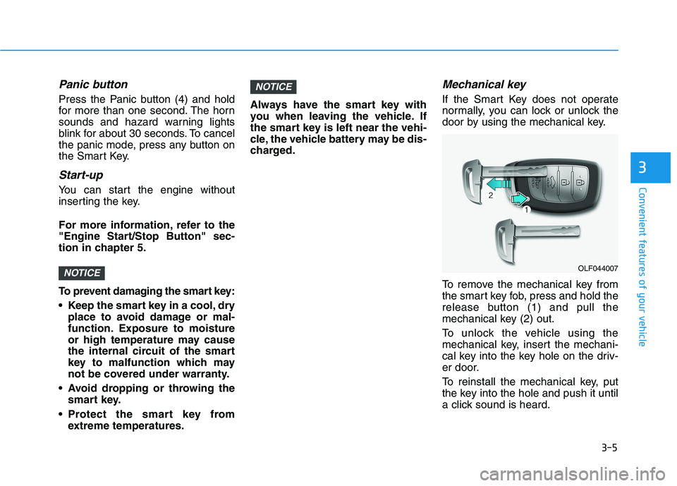
If the Smart Key does not operate
normally, you can lock or unlock the
door by using the mechanical key.
To remove the mechanical key from
the smart key fob, press and hold the
release button (1) and pull the
mechanical key (2) out.
To unlock the vehicle using the
mechanical key, insert the mechani-
cal key into the key hole on the driv-
er door.
To reinstall the mechanical key, put
the key into the hole and push it until
a click sound is heard.
NOTICE
NOTICEOLF044007