2019 FORD F650/750 stop start
[x] Cancel search: stop startPage 172 of 387

Protected Component
Fuse Rating
Fuse or Relay
Number
Vehicle power 2.
20A 2
34
Vehicle power 3.
10A 2
35
Vehicle power 4.
20A 2
36
Vehicle power 5 (diesel engine).
10A 2
37
Powertrain control module.
Relay
38
Not used.
—
39
Heated mirrors.
15A 2
40
Not used.
—
41
Trailer tow and body builder stop lamps.
20A 2
42
Not used.
—
43
Ancillary translator module.
20A 2
44
Run/start relay coil.
10A 2
45
Transmission control module keep-alive
power (diesel engine).
10A 2
46
A/C clutch.
10A 2
47
Run/start.
Relay
48
Air dryer.
20A 2
49
Blower motor relay coil.
10A 2
50
Not used.
—
51
Powertrain control module run/start
(diesel engine).
10A 2
52
Transmission control module run/start
(diesel engine).
Not used.
—
53
Anti-lock brake system run/start.
10A 2
54
169
F650750 (TBC) , enUSA, Edition date: 201804, Second-Printing Fuses
Page 175 of 387

Protected Component
Fuse Rating
Fuse or Relay
Number
Not used.
—
98
Instrument panel 110 volt power inverter.
40A 1
99
Trailer tow turn lamp relays.
30A 1
100
Starter.
Relay
101
Trailer tow battery charge relay (U-Haul).
Relay
102
Trailer tow battery feed (air brakes).
Trailer tow right hand side turn and stop
lamps.
Relay
103
Trailer tow left hand side turn and stop
lamps.
Relay
104
Not used.
—
105
Trailer tow backup lamps.
Relay
106
Passenger air ride seat compressor.
Relay
107
1 J-case fuse.
2 Mini fuse.
Passenger Compartment Fuse
Panel
The fuse panel is in the passenger footwell.
Remove the panel cover to access the
fuses. Pull the fuse panel cover toward you to
remove it. When the clips of the panel
disengage, let the panel fall easily.
Use the provided fuse puller tool to remove
a fuse. It is on the fuse panel cover.
172
F650750 (TBC) , enUSA, Edition date: 201804, Second-Printing Fuses
Page 182 of 387

Engine compartment (with engine off)
Inspect for glazing, fraying or cracking. There should be no
more than 5-7 cracks per rib, per 1 in (2.5 cm)
Belts (fan, alternator,
water pump and air
conditioning
compressor)
Inspect for signs of fluid puddles or dripping fluid on the
ground under the engine, or the underside of the engine.
Fluid leaks
Inspect for debris that may have collected on the HVAC air
inlet grille or inside the exterior module as this may reduce
system performance.
HVAC air inlet Engine starting (with parking brake applied)
Before entering the cab, verify that the vehicle is equipped
with spare electrical fuses (if used), three red reflective
triangles, a properly charged and rated fire extinguisher and
wheel chocks.
Safety and emergency
equipment
Walk around the vehicle and verify all steps and grab handles,
inside and out (as well as behind), are tight and clean. Use
extreme caution and a three-point stance at all times.
Inspect door latches for proper closing, latching and locking.
Set the parking brake. Make sure the gearshift lever is in
neutral (N) or park (P) (if equipped with a park position).
Starting the engine
Diesel engine:
Turn the key to the on position. Turn the key
to start when the wait to start indicator light in the instrument
cluster turns off.
Gasoline engine:
Turn the key to start, and then release it
as soon as the engine starts.
Verify pressure builds to normal operating range.
Engine oil pressure
A tone indicating low air pressure should sound immediately
after the engine starts but before the compressor has built-
up pressure. The tone should stop when the air pressure
reaches
70 psi (483 kPa). Let the air pressure build to
governed cutout pressure, which should occur between
115– 130 psi (793–896 kPa)
.
Low air pressure warning
tone (if equipped with an
air compressor)
Press the accelerator and verify that it operates smoothly,
without any binding or irregular feel. Release the pedal and
verify the engine returns to idle speed immediately.
Accelerator
179
F650750 (TBC) , enUSA, Edition date: 201804, Second-Printing Vehicle Inspection Guide
Page 203 of 387

Engine-driven Cooling Fan
Your vehicle may have an engine driven
cooling fan drive also called a fan clutch.
This fan drive changes the fan speed to
match the vehicle
’s changing cooling air
flow requirements. Fan speed, fan noise
level and fuel consumption all will increase
based on the driving conditions that
include trailer towing, hill climbing, heavy
loads, high speed and high ambient
temperature, individually or in combination.
The fan drive is designed to provide the
minimum fan speed and resulting
minimum fan noise and fuel consumption
required to meet the ever-changing vehicle
cooling air flow requirements. You can hear
the amount of fan noise increasing and
decreasing as the engine power
requirements and vehicle driving conditions
change as you drive. This is normal to the
operation of your vehicle. You may also
hear high levels of the fan when the engine
is first started and should normally
decrease after driving for a short time.
ENGINE COOLANT CHECK -
6.8L WARNING: Do not remove the
coolant reservoir cap when the engine is
on or the cooling system is hot. Wait 10
minutes for the cooling system to cool
down. Cover the coolant reservoir cap
with a thick cloth to prevent the
possibility of scalding and slowly remove
the cap. Failure to follow this instruction
could result in personal injury. WARNING:
Do not put coolant in
the windshield washer reservoir. If
sprayed on the windshield, coolant could
make it difficult to see through the
windshield. WARNING:
To reduce the risk of
personal injury, make sure the engine is
cool before unscrewing the coolant
pressure relief cap. The cooling system
is under pressure. Steam and hot liquid
can come out forcefully when you loosen
the cap slightly. WARNING:
Do not add coolant
further than the MAX mark.
When the engine is cold, check the
concentration and level of the coolant at
the intervals listed in the scheduled
maintenance information. See Scheduled
Maintenance
(page 322).
Note: Make sure that the coolant level is
between the
MIN and the MAX marks on
the coolant reservoir.
Note: Coolant expands when it is hot. The
level may extend beyond the
MAX mark.
Maintain coolant concentration within
48% to 50%, which equates to a freeze
point between -30°F (-34°C) and -34°F
(-37°C). Coolant concentration should be
checked using a refractometer. We
recommend Robinair® Coolant and
Battery Refractometer 75240 (Rotunda
tool part number: ROB75240). We do not
recommend the use of hydrometers or
coolant test strips for measuring coolant
concentration.
Note: Automotive fluids are not
interchangeable. Do not use coolant or
windshield washer fluid outside of its
specified function and vehicle location.
Note: Do not use stop leak pellets, cooling
system sealants, or additives as they can
cause damage to the engine cooling or
heating systems. Resulting component
damage may not be covered by the vehicle
Warranty.
200
F650750 (TBC) , enUSA, Edition date: 201804, Second-Printing Maintenance
Page 210 of 387

DRAINING THE FUEL FILTER
WATER TRAP - 6.7L DIESEL
Your vehicle is equipped with a diesel fuel
conditioner module located on the
frame-rail under the driver-side floorboard
near the transmission.
You should drain water from the
module assembly whenever the
warning light comes on and the
message center directs you to drain the
water separator. This will occur when
approximately 8.45 fl oz (250 ml) of water
accumulates in the module. If you allow
the water level to exceed this level, the
water may pass through to the engine and
may cause fuel injection equipment
damage.
Draining the Diesel Fuel
Conditioner Module (DFCM) WARNING: Do not drain the
water-in-fuel separator while the engine
is running. Failure to follow this warning
may result in fire, serious injury, death or
property damage.
Note: If you drain the diesel fuel conditioner
module while the system is running air will
enter into the fuel system. The engine will
not operate properly if air enters the system.
Note: With fuel tank levels above 3⁄4 tank
it may be necessary to loosen the bowl three
turns before opening the drain. This will
actuate an anti-siphon valve at the fuel and
water separator inlet and prevent the fuel
from siphoning out of the tank.
Note: A loose drain valve can allow air to
enter the fuel system and cause drivetrain
issues. The engine will not operate properly.
Be sure that you fully tighten the drain valve.
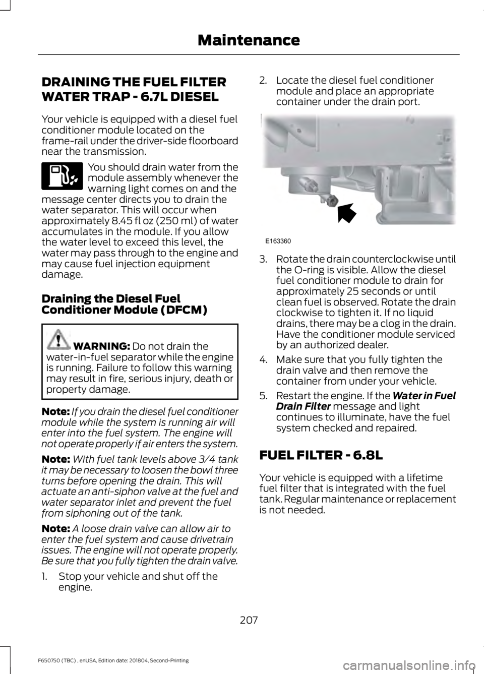
1. Stop your vehicle and shut off the engine. 2. Locate the diesel fuel conditioner
module and place an appropriate
container under the drain port. 3.
Rotate the drain counterclockwise until
the O-ring is visible. Allow the diesel
fuel conditioner module to drain for
approximately 25 seconds or until
clean fuel is observed. Rotate the drain
clockwise to tighten it. If no liquid
drains, there may be a clog in the drain.
Have the conditioner module serviced
by an authorized dealer.
4. Make sure that you fully tighten the drain valve and then remove the
container from under your vehicle.
5. Restart the engine. If the Water in Fuel
Drain Filter
message and light
continues to illuminate, have the fuel
system checked and repaired.
FUEL FILTER - 6.8L
Your vehicle is equipped with a lifetime
fuel filter that is integrated with the fuel
tank. Regular maintenance or replacement
is not needed.
207
F650750 (TBC) , enUSA, Edition date: 201804, Second-Printing Maintenance E163360
Page 211 of 387

CHANGING THE 12V BATTERY
WARNING: This vehicle may be
equipped with more than one battery,
removal of cable from only one battery
does not disconnect the vehicle
electrical system. Be sure to disconnect
cables from all batteries when
disconnecting power. Failure to do so
may cause serious personal injury or
property damage. WARNING:
Batteries normally
produce explosive gases which can
cause personal injury. Therefore, do not
allow flames, sparks or lighted
substances to come near the battery.
When working near the battery, always
shield your face and protect your eyes.
Always provide proper ventilation. WARNING:
When lifting a
plastic-cased battery, excessive pressure
on the end walls could cause acid to flow
through the vent caps, resulting in
personal injury and damage to the
vehicle or battery. Lift the battery with a
battery carrier or with your hands on
opposite corners. WARNING:
Keep batteries out of
reach of children. Batteries contain
sulfuric acid. Avoid contact with skin,
eyes or clothing. Shield your eyes when
working near the battery to protect
against possible splashing of acid
solution. In case of acid contact with skin
or eyes, flush immediately with water for
a minimum of 15 minutes and get prompt
medical attention. If acid is swallowed,
call a physician immediately.
Note: If your battery has a cover/shield,
make sure it is reinstalled after the battery
has been cleaned or replaced. Note:
Battery posts, terminals and related
accessories contain lead and lead
compounds. Wash hands after handling.
Note: Electrical or electronic accessories
or components added to the vehicle by the
dealer or the owner may adversely affect
battery performance and durability.
Your vehicle is equipped with a Motorcraft
maintenance-free battery which normally
does not require additional water during
its life of service.
For longer, trouble-free operation, keep the
top of the battery clean and dry. Also,
make certain the battery cables are always
tightly fastened to the battery terminals.
If you see any corrosion on the battery or
terminals, remove the cables from the
terminals and clean with a wire brush. You
can neutralize the acid with a solution of
baking soda and water.
It is recommended that the negative
battery cable terminal be disconnected
from the battery if you plan to store your
vehicle for an extended period of time.
Because your vehicle ’s engine is
electronically controlled by a computer,
some control conditions are maintained
by power from the battery. When the
battery is disconnected or a new battery
is installed, the engine must relearn its idle
and fuel trim strategy for optimum
driveability and performance. To begin this
process
1. With the vehicle at a complete stop, set the parking brake.
2. Put the gearshift in park (P) or neutral (N) and turn off all accessories.
3. Start the engine. Run the engine until it reaches normal operating
temperature.
4. Allow the engine to idle for at least one
minute.
208
F650750 (TBC) , enUSA, Edition date: 201804, Second-Printing Maintenance
Page 252 of 387

Safety Practices
WARNING: If your vehicle
is stuck in snow, mud or sand, do
not rapidly spin the tires;
spinning the tires can tear the
tire and cause an explosion. A
tire can explode in as little as
three to five seconds. WARNING: Do not spin the
wheels at over
34 mph
(55 km/h). The tires may fail and
injure a passenger or bystander.
Driving habits have a great deal
to do with your tire mileage and
safety.
• Observe posted speed limits
• Avoid fast starts, stops and
turns
• Avoid potholes and objects on
the road
• Do not run over curbs or hit the
tire against a curb when
parking
Highway Hazards
No matter how carefully you drive
there ’s always the possibility that
you may eventually have a flat tire
on the highway. Drive slowly to the
closest safe area out of traffic.
This may further damage the flat
tire, but your safety is more
important. If you feel a sudden vibration or
ride disturbance when driving, or
you suspect your tire or vehicle
has been damaged, immediately
reduce your speed. Drive with
caution until you can safely pull
off the road. Stop and inspect the
tires for damage. If a tire is
under-inflated or damaged,
deflate it, remove wheel and
replace it with your spare tire and
wheel. If you cannot detect a
cause, have the vehicle towed to
the nearest repair facility or tire
dealer to have the vehicle
inspected.
Tire and Wheel Alignment
A bad jolt from hitting a curb or
pothole can cause the front end
of your vehicle to become
misaligned or cause damage to
your tires. If your vehicle seems to
pull to one side when you’re
driving, the wheels may be out of
alignment. Have an authorized
dealer check the wheel alignment
periodically.
Wheel misalignment in the front
or the rear can cause uneven and
rapid treadwear of your tires and
should be corrected by an
authorized dealer. Front-wheel
drive vehicles and those with an
independent rear suspension may
require alignment of all four
wheels.
The tires should also be balanced
periodically. An unbalanced tire
and wheel assembly may result in
irregular tire wear.
249
F650750 (TBC) , enUSA, Edition date: 201804, Second-Printing Wheels and Tires
Page 385 of 387

Selective Catalytic Reductant System -
Diesel.............................................................105
Contaminated Diesel Exhaust Fluid or Inoperative Selective Catalytic Reduction
System.............................................................. 109
Diesel Exhaust Fluid Guidelines and Information...................................................... 108
Diesel Exhaust Fluid Level.............................. 105
Diesel Exhaust Fluid Warning Messages and Vehicle Operations............................... 107
Filling the Diesel Exhaust Fluid Tank..........105
Sitting in the Correct Position....................75
Snow Chains See: Using Snow Chains.................................. 251
Spare Wheel See: Changing a Road Wheel......................... 251
Special Notices................................................14
Fleet Telematics Modem.................................... 14
FordPass Connect................................................. 14
New Vehicle Limited Warranty......................... 14
Special Instructions.............................................. 14
Special Operating Conditions Scheduled Maintenance................................................331
Diesel Engine....................................................... 334
Exceptions............................................................ 339
Gasoline Engines................................................. 331
Speed Control See: Cruise Control............................................ 138
Spring U-Bolt Check...................................228 U-bolt Nut Torque............................................. 228
Stability Control
............................................135
Principle of Operation....................................... 135
Starter Switch See: Ignition Switch............................................ 86
Starting a Diesel Engine..............................88 ........................................................................\
............ 88
Cold Weather Starting....................................... 89
Diesel Engine Fast Start Glow Plug System................................................................ 88
Starting a Gasoline Engine.........................87 Failure to Start....................................................... 87
Guarding Against Exhaust Fumes.................. 87
Important Ventilating Information................88
Stopping the Engine When Your Vehicle is Moving................................................................. 87
Stopping the Engine When Your Vehicle is Stationary........................................................... 87Starting and Stopping the Engine...........86
General Information........................................... 86
Steering............................................................140
Steering System Inspection.....................226 Hydraulic System............................................... 226
Steering Column Joint Bolts.......................... 226
Steering Wheel
...............................................46
Storage Compartments..............................85
Sun Visors.........................................................55 Slide-on-rod........................................................... 55
Suspension System Inspection
..............227
Switching Off the Engine............................89
Symbols Glossary...........................................10
SYNC™............................................................287
General Information.......................................... 287
SYNC™ Troubleshooting
...........................312
T
Technical Specifications See: Capacities and Specifications............255
The Better Business Bureau (BBB) Auto Line Program (U.S. Only)........................162
Tire Care
..........................................................236
Glossary of Tire Terminology......................... 236
Information Contained on the Tire Sidewall............................................................ 236
Tires See: Wheels and Tires..................................... 236
Towing a Trailer
.............................................144
Load Placement................................................. 144
Towing..............................................................144
Traction Control
............................................133
Principle of Operation....................................... 133
Trailer Brakes
..................................................129
Trailer Air Supply and Parking Brake
Modular Controls........................................... 129
Trailer Brake Hand Control.............................. 129
Transmission Code Designation............260
Transmission...................................................115
Transporting the Vehicle
...........................158
U
Under Hood Overview - 6.7L Diesel
.............................................................190
Under Hood Overview - 6.8L....................191
USB Port
.........................................................285
382
F650750 (TBC) , enUSA, Edition date: 201804, Second-Printing Index