Page 249 of 490
Fuel Economy (ECON) Mode
The Fuel Economy (ECON) mode can improve the vehi-
cle’s overall fuel economy during normal driving condi-
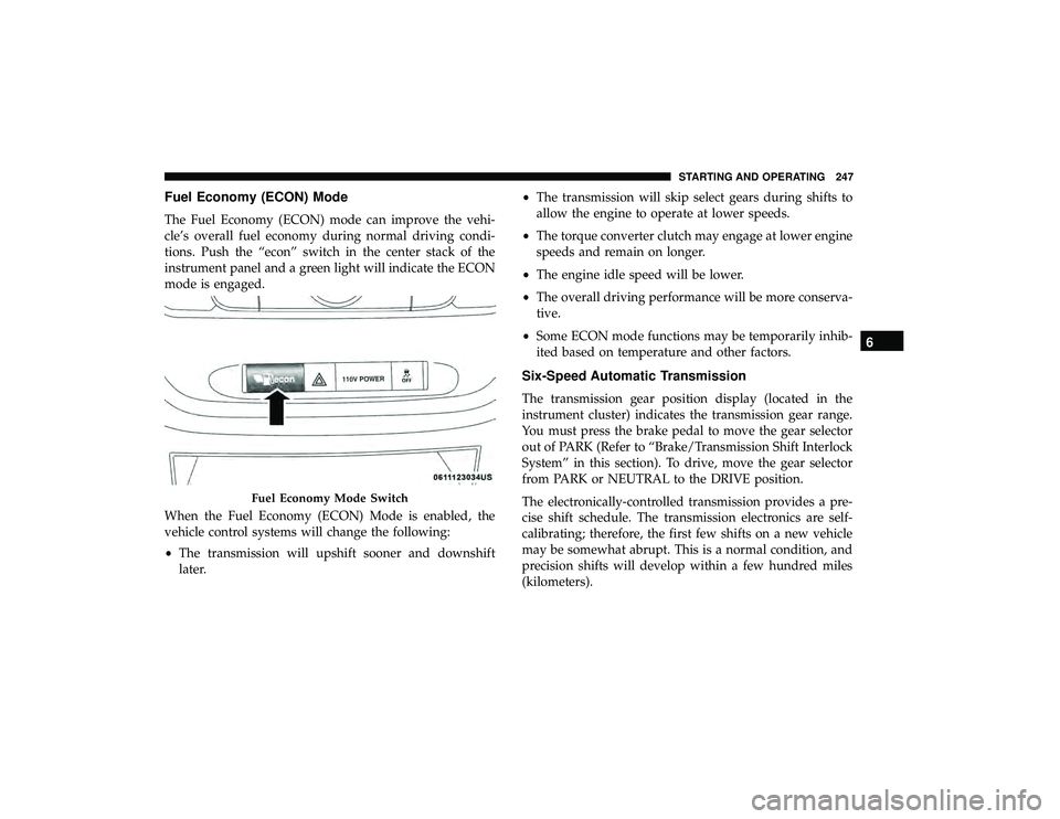
tions. Push the “econ” switch in the center stack of the
instrument panel and a green light will indicate the ECON
mode is engaged.
When the Fuel Economy (ECON) Mode is enabled, the
vehicle control systems will change the following:
•The transmission will upshift sooner and downshift
later. •
The transmission will skip select gears during shifts to
allow the engine to operate at lower speeds.
• The torque converter clutch may engage at lower engine
speeds and remain on longer.
• The engine idle speed will be lower.
• The overall driving performance will be more conserva-
tive.
• Some ECON mode functions may be temporarily inhib-
ited based on temperature and other factors.
Six-Speed Automatic Transmission
The transmission gear position display (located in the
instrument cluster) indicates the transmission gear range.
You must press the brake pedal to move the gear selector
out of PARK (Refer to “Brake/Transmission Shift Interlock
System” in this section). To drive, move the gear selector
from PARK or NEUTRAL to the DRIVE position.
The electronically-controlled transmission provides a pre-
cise shift schedule. The transmission electronics are self-
calibrating; therefore, the first few shifts on a new vehicle
may be somewhat abrupt. This is a normal condition, and
precision shifts will develop within a few hundred miles
(kilometers).
Fuel Economy Mode Switch
6
STARTING AND OPERATING 247
Page 258 of 490
WARNING!
Speed Control can be dangerous where the system
cannot maintain a constant speed. Your vehicle could
go too fast for the conditions, and you could lose
control and have an accident. Do not use Speed Control
in heavy traffic or on roads that are winding, icy,
snow-covered or slippery.
To Activate
Push the ON/OFF button. The Cruise Indicator Light in
the instrument cluster display will illuminate. To turn the
system off, push the ON/OFF button a second time. The
Cruise Indicator Light will turn off. The system should be
turned off when not in use.
WARNING!
Leaving the Speed Control system on when not in use
is dangerous. You could accidentally set the system or
cause it to go faster than you want. You could lose
control and have an accident. Always leave the system
off when you are not using it.
To Set A Desired Speed
Turn the Speed Control on. When the vehicle has reached
the desired speed, push the SET (-) button and release.
Release the accelerator and the vehicle will operate at the
selected speed.
NOTE:The vehicle should be traveling at a steady speed
and on level ground before pushing the SET (-) button.
To Vary The Speed Setting
To Increase Speed
When the Speed Control is set, you can increase speed by
pushing the RES (+) button.
The driver ’s preferred units can be selected through the
instrument panel settings if equipped. Refer to “Getting To
Know Your Instrument Panel” for more information. The
speed decrement shown is dependant on the chosen speed
unit of U.S. (mph) or Metric (km/h):
U.S. Speed (mph)
• Pushing the RES (+) button once will result ina1mph
increase in set speed. Each subsequent tap of the button
results in an increase of 1 mph.
256 STARTING AND OPERATING
Page 259 of 490
•If the button is continually pushed, the set speed will
continue to increase until the button is released, then the
new set speed will be established.
Metric Speed (km/h)
• Pushing the RES (+) button once will result in a 1 km/h
increase in set speed. Each subsequent tap of the button
results in an increase of 1 km/h.
• If the button is continually pushed, the set speed will
continue to increase until the button is released, then the
new set speed will be established.
To Decrease Speed
When the Speed Control is set, you can decrease speed by
pushing the SET (-) button.
The driver ’s preferred units can be selected through the
instrument panel settings if equipped. Refer to “Getting To
Know Your Instrument Panel” for more information. The
speed decrement shown is dependant on the chosen speed
unit of U.S. (mph) or Metric (km/h):
U.S. Speed (mph)
• Pushing the SET (-) button once will result ina1mph
decrease in set speed. Each subsequent tap of the button
results in a decrease of 1 mph. •
If the button is continually pushed, the set speed will
continue to decrease until the button is released, then the
new set speed will be established.
Metric Speed (km/h)
• Pushing the SET (-) button once will result in a 1 km/h
decrease in set speed. Each subsequent tap of the button
results in a decrease of 1 km/h.
• If the button is continually pushed, the set speed will
continue to decrease until the button is released, then the
new set speed will be established.
To Accelerate For Passing
Press the accelerator as you would normally. When the
pedal is released, the vehicle will return to the set speed.
Using Speed Control On Hills
The transmission may downshift on hills to maintain the
vehicle set speed.
NOTE: The Speed Control system maintains speed up and
down hills. A slight speed change on moderate hills is
normal.
On steep hills, a greater speed loss or gain may occur so it
may be preferable to drive without Speed Control.
6
STARTING AND OPERATING 257
Page 261 of 490
ParkSense Sensors
The four ParkSense sensors, located in the rear fascia/
bumper, monitor the area behind the vehicle that is within
the sensors’ field of view. The sensors can detect obstacles
from approximately 12 inches (30 cm) up to 79 inches (200
cm) from the rear fascia/bumper in the horizontal direc-
tion, depending on the location, type and orientation of the
obstacle.
ParkSense Warning Display
The ParkSense Warning Display is located in the instru-
ment cluster display. It provides both visual and audible
warnings to indicate the distance between the rear fascia/
bumper and the detected obstacle.The ParkSense Warning screen will only be displayed if
Sound and Display is selected from the Customer-
Programmable Features section of the instrument cluster
display. Refer to “Instrument Cluster Display” in “Getting
To Know Your Instrument Panel” for further information.
ParkSense Warning Display
6
STARTING AND OPERATING 259
Page 265 of 490
NOTE:ParkSense will reduce the radio volume, if on,
when the system is sounding an audio tone.
Enabling/Disabling ParkSense
ParkSense can be enabled and disabled through the
Customer-Programmable Features section of the instru-
ment cluster display. The available choices are: OFF, Sound
Only, or Sound and Display.
When ParkSense is disabled, the instrument cluster will
display the “PARK ASSIST SYSTEM OFF” message for
approximately five seconds. When the gear selector is
moved to REVERSE and the system is disabled, the instru-
ment cluster display will display the “PARK ASSIST SYS-
TEM OFF” message for as long as the vehicle is in
REVERSE.
Refer to “Instrument Cluster Display” in “Getting To Know
Your Instrument Panel” for further information.
Service The ParkSense Rear Park Assist System
During vehicle start up, when the ParkSense Rear Park
Assist System has detected a faulted condition, the instru-
ment cluster will actuate a single chime, once per ignition
cycle, and it will display the “SERVICE PARK ASSIST
SYSTEM” message. When the gear selector is moved to
REVERSE and the system has detected a faulted condition, the instrument cluster display will display the “SERVICE
PARK ASSIST SYSTEM” message for as long as the vehicle
is in REVERSE. Under this condition, ParkSense will not
operate.
Refer to “Instrument Cluster Display” in “Getting To Know
Your Instrument Panel” for further information.
If “SERVICE PARK ASSIST SYSTEM” appears in the in-
strument cluster display after making sure the rear fascia/
bumper is free from snow, ice, mud, dirt and debris, see
your authorized dealer.
Cleaning The ParkSense System
Clean the ParkSense sensors with water, car wash soap and
a soft cloth. Do not use rough or hard cloths. Do not scratch
or poke the sensors. Otherwise, you could damage the
sensors.
ParkSense System Usage Precautions
NOTE:
•
Ensure that the rear bumper is free of snow, ice, mud,
dirt and debris to keep the ParkSense system operating
properly.
• Jackhammers, large trucks, and other vibrations could
affect the performance of ParkSense.
6
STARTING AND OPERATING 263
Page 288 of 490
HAZARD WARNING FLASHERS
The Hazard Warning flasher switch is located in the lower
center area of the instrument panel.Push the switch to turn on the Hazard Warning
flasher. When the switch is activated, all direc-
tional turn signals will flash on and off to warn
oncoming traffic of an emergency. Push the
switch a second time to turn off the Hazard Warning
flashers. This is an emergency warning system and it should not be
used when the vehicle is in motion. Use it when your
vehicle is disabled and it is creating a safety hazard for
other motorists.
When you must leave the vehicle to seek assistance, the
Hazard Warning flashers will continue to operate even
though the ignition is placed in the OFF position.
NOTE:
With extended use, the Hazard Warning flashers
may wear down your battery.
286 IN CASE OF EMERGENCY
Page 296 of 490
CavityCartridge Fuse Mini-Fuse Description
J15 40 Amp Green –Front Blower
J17 40 Amp Green –Starter Solenoid
J18 20 Amp Blue –Powertrain Control Module Trans Range
J19 60 Amp Yellow –Radiator Fan
J20 30 Amp Pink –Front Wiper LO/HI
J21 20 Amp Blue –Front/Rear Washer
J22 25 Amp Clear –Sunroof Module
M1 –15 Amp Blue Rear Center Brake Lamp/Brake Switch
M2 –20 Amp Yellow Front Fog Lamps
M3 –20 Amp Yellow Vacuum Pump Motor
M5 –25 Amp Clear Inverter
M6 –20 Amp Yellow Power Outlet #1 (ACC), Rain Sensor, Cigar
Lighter (Instrument Panel or with ConsoleRear)
M7 –20 Amp Yellow Power Outlet #2 (BATT/ACC SELECT) –
Center Seat or with Console Rear
M8 –20 Amp Yellow Front Heated Seat — If Equipped
M9 –20 Amp Yellow Rear Heated Seat — If Equipped
294 IN CASE OF EMERGENCY
Page 299 of 490
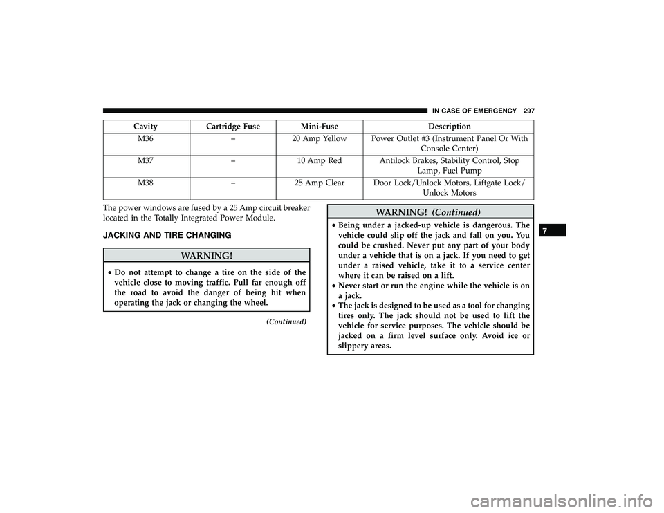
CavityCartridge Fuse Mini-Fuse Description
M36 –20 Amp Yellow Power Outlet #3 (Instrument Panel Or With
Console Center)
M37 –10 Amp Red Antilock Brakes, Stability Control, Stop
Lamp, Fuel Pump
M38 –25 Amp Clear Door Lock/Unlock Motors, Liftgate Lock/
Unlock Motors
The power windows are fused by a 25 Amp circuit breaker
located in the Totally Integrated Power Module.
JACKING AND TIRE CHANGING
WARNING!
• Do not attempt to change a tire on the side of the
vehicle close to moving traffic. Pull far enough off
the road to avoid the danger of being hit when
operating the jack or changing the wheel.
(Continued)
WARNING! (Continued)
•Being under a jacked-up vehicle is dangerous. The
vehicle could slip off the jack and fall on you. You
could be crushed. Never put any part of your body
under a vehicle that is on a jack. If you need to get
under a raised vehicle, take it to a service center
where it can be raised on a lift.
• Never start or run the engine while the vehicle is on
a jack.
• The jack is designed to be used as a tool for changing
tires only. The jack should not be used to lift the
vehicle for service purposes. The vehicle should be
jacked on a firm level surface only. Avoid ice or
slippery areas.7
IN CASE OF EMERGENCY 297