Page 295 of 490
The numbers inside the TIPM cover correspond to the
following table.
CavityCartridge Fuse Mini-Fuse Description
J1 40 Amp Green –Power Folding Seat
J2 30 Amp Pink –Power Liftgate Module
J3 30 Amp Pink –Rear Door Module
J4 25 Amp Clear –Driver Door Node
J5 25 Amp Clear –Passenger Door Node
J6 40 Amp Green –Antilock Brakes Pump/Stability Control Sys-
tem
J7 30 Amp Pink –Antilock Brakes Valve/Stability Control Sys-
tem
J8 40 Amp Green –Power Memory Seat – If Equipped
J9 –– Not Used
J10 30 Amp Pink –Headlamp Wash/Manifold Tuning Valve – If
Equipped
J11 30 Amp Pink –Power Sliding Door Module/Anti–Theft
Module – If Equipped
J12 30 Amp Pink –HVAC Rear Blower, Radiator Fan Motor
J13 60 Amp Yellow –Ignition Off Draw (IOD) – Main
J14 40 Amp Green –Rear Window Defogger
7
IN CASE OF EMERGENCY 293
Page 299 of 490
CavityCartridge Fuse Mini-Fuse Description
M36 –20 Amp Yellow Power Outlet #3 (Instrument Panel Or With
Console Center)
M37 –10 Amp Red Antilock Brakes, Stability Control, Stop
Lamp, Fuel Pump
M38 –25 Amp Clear Door Lock/Unlock Motors, Liftgate Lock/
Unlock Motors
The power windows are fused by a 25 Amp circuit breaker
located in the Totally Integrated Power Module.
JACKING AND TIRE CHANGING
WARNING!
• Do not attempt to change a tire on the side of the
vehicle close to moving traffic. Pull far enough off
the road to avoid the danger of being hit when
operating the jack or changing the wheel.
(Continued)
WARNING! (Continued)
•Being under a jacked-up vehicle is dangerous. The
vehicle could slip off the jack and fall on you. You
could be crushed. Never put any part of your body
under a vehicle that is on a jack. If you need to get
under a raised vehicle, take it to a service center
where it can be raised on a lift.
• Never start or run the engine while the vehicle is on
a jack.
• The jack is designed to be used as a tool for changing
tires only. The jack should not be used to lift the
vehicle for service purposes. The vehicle should be
jacked on a firm level surface only. Avoid ice or
slippery areas.7
IN CASE OF EMERGENCY 297
Page 303 of 490
Spare Tire Removal
The spare tire is stowed inside a protective cover located
under the center of the vehicle between the front doors by
means of a cable winch mechanism. The “spare tire drive”
nut is located on the floor, under a plastic cap at the front
of the floor console or under front super console forward
bin liner.
Spare Tire Removal Instructions
The spare tire is located under the vehicle beneath the
center console area.
1. Assemble the spare tire tools into a T-handle and placethe square end over the spare tire winch drive nut.
2. Rotate the nut to the left until the winch mechanism stops turning freely. This will allow enough slack in the
cable to allow you to pull the spare tire out from
underneath the vehicle.
Spare Tire Location
Spare Tire And Cover
7
IN CASE OF EMERGENCY 301
Page 321 of 490
NOTE:Sealant may leak out through the puncture in the
tire.
If the sealant (white fluid) does not flow within0–10
seconds through the Sealant Hose:
1. Push the Power Button to turn Off the Tire Service Kit. Disconnect the Sealant Hose from the valve stem. Make
sure the valve stem is free of debris. Reconnect the
Sealant Hose to the valve stem. Check that the Mode
Select Knob is in the Sealant Mode position and not Air
Mode. Push the Power Button to turn On the Tire
Service Kit.
2. Connect the Power Plug to a different 12 Volt power outlet in your vehicle or another vehicle, if available.
Make sure the vehicle is running before turning ON the
Tire Service Kit.
3. The Sealant Bottle may be empty due to previous use. Call for assistance. If the sealant (white fluid) does flow through the Sealant
Hose:
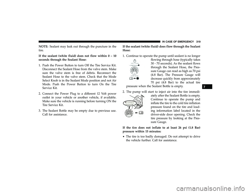
1. Continue to operate the pump until sealant is no longer
flowing through hose (typically takes
30 - 70 seconds). As the sealant flows
through the Sealant Hose, the Pres-
sure Gauge can read as high as 70 psi
(4.8 Bar). The Pressure Gauge will
decrease quickly from approximately
70 psi (4.8 Bar) to the actual tire
pressure when the Sealant Bottle is empty.
2. The pump will start to inject air into the tire immedi- ately after the Sealant Bottle is empty.
Continue to operate the pump and
inflate the tire to the cold tire inflation
pressure found on the tire and load-
ing information label located in the
driver-side door opening. Check the
tire pressure by looking at the Pres-
sure Gauge.
If the tire does not inflate to at least 26 psi (1.8 Bar)
pressure within 15 minutes:
• The tire is too badly damaged. Do not attempt to drive
the vehicle further. Call for assistance.
7
IN CASE OF EMERGENCY 319
Page 324 of 490
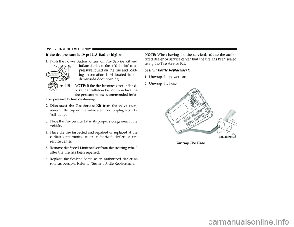
If the tire pressure is 19 psi (1.3 Bar) or higher:
1. Push the Power Button to turn on Tire Service Kit andinflate the tire to the cold tire inflation
pressure found on the tire and load-
ing information label located in the
driver-side door opening.
NOTE: If the tire becomes over-inflated,
push the Deflation Button to reduce the
tire pressure to the recommended infla-
tion pressure before continuing.
2. Disconnect the Tire Service Kit from the valve stem, reinstall the cap on the valve stem and unplug from 12
Volt outlet.
3. Place the Tire Service Kit in its proper storage area in the vehicle.
4. Have the tire inspected and repaired or replaced at the earliest opportunity at an authorized dealer or tire
service center.
5. Remove the Speed Limit sticker from the steering wheel after the tire has been repaired.
6. Replace the Sealant Bottle at an authorized dealer as soon as possible. Refer to “Sealant Bottle Replacement”. NOTE:
When having the tire serviced, advise the autho-
rized dealer or service center that the tire has been sealed
using the Tire Service Kit.
Sealant Bottle Replacement:
1. Unwrap the power cord.
2. Unwrap the hose.
Unwrap The Hose
322 IN CASE OF EMERGENCY
Page 347 of 490
CAUTION!
Do not use chemical flushes in your air conditioning
system as the chemicals can damage your air condition-
ing components. Such damage is not covered by the
New Vehicle Limited Warranty.
Refrigerant Recovery And Recycling R-134a — If
Equipped
R-134a Air Conditioning Refrigerant is a hydrofluoro-
carbon (HFC) that is an ozone-friendly substance. The
manufacturer recommends that air conditioning service be
performed by an authorized dealer or other service facili-
ties using recovery and recycling equipment.
NOTE:Use only manufacturer approved A/C system PAG
compressor oil and refrigerants.
A/C Air Filter
Refer to the “Maintenance Plan” in the “Scheduled Servic-
ing” chapter for the proper maintenance intervals.
WARNING!
Do not remove the cabin air filter while the vehicle is
running, or while the ignition is in the ACC or ON/
RUN mode. With the cabin air filter removed and the
blower operating, the blower can contact hands and
may propel dirt and debris into your eyes, resulting in
personal injury.
The A/C air filter is located in the fresh air inlet behind the
glove compartment. Perform the following procedure to
replace the filter:
1. Open the glove compartment and remove all contents.
2. Push in on the sides of the glove compartment, remove tether and lower the door.
3. Pivot the glove compartment downward.
4. Disengage the two retaining tabs that secure the filter cover to the HVAC housing, and remove the cover.
8
SERVICING AND MAINTENANCE 345
Page 349 of 490
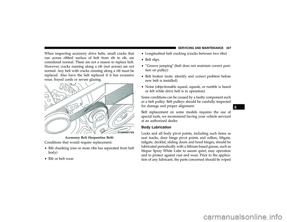
When inspecting accessory drive belts, small cracks that
run across ribbed surface of belt from rib to rib, are
considered normal. These are not a reason to replace belt.
However, cracks running along a rib (not across) are not
normal. Any belt with cracks running along a rib must be
replaced. Also have the belt replaced if it has excessive
wear, frayed cords or severe glazing.
Conditions that would require replacement:
•Rib chunking (one or more ribs has separated from belt
body)
• Rib or belt wear •
Longitudinal belt cracking (cracks between two ribs)
• Belt slips
• “Groove jumping� (belt does not maintain correct posi-
tion on pulley)
• Belt broken (note: identify and correct problem before
new belt is installed)
• Noise (objectionable squeal, squeak, or rumble is heard
or felt while drive belt is in operation)
Some conditions can be caused by a faulty component such
as a belt pulley. Belt pulleys should be carefully inspected
for damage and proper alignment.
Belt replacement on some models requires the use of
special tools, we recommend having your vehicle serviced
at an authorized dealer.
Body Lubrication
Locks and all body pivot points, including such items as
seat tracks, door hinge pivot points and rollers, liftgate,
tailgate, decklid, sliding doors and hood hinges, should be
lubricated periodically with a lithium based grease, such as
Mopar Spray White Lube to assure quiet, easy operation
and to protect against rust and wear. Prior to the applica-
tion of any lubricant, the parts concerned should be wiped
Accessory Belt (Serpentine Belt)
8
SERVICING AND MAINTENANCE 347
Page 364 of 490
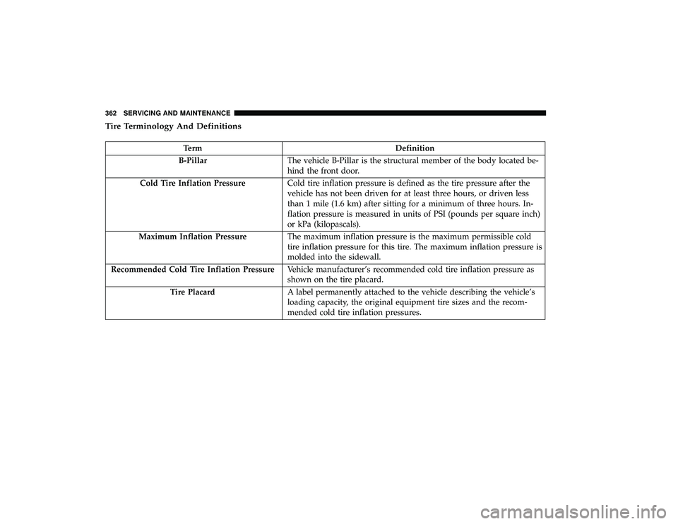
Tire Terminology And Definitions
TermDefinition
B-Pillar The vehicle B-Pillar is the structural member of the body located be-
hind the front door.
Cold Tire Inflation Pressure Cold tire inflation pressure is defined as the tire pressure after the
vehicle has not been driven for at least three hours, or driven less
than 1 mile (1.6 km) after sitting for a minimum of three hours. In-
flation pressure is measured in units of PSI (pounds per square inch)
or kPa (kilopascals).
Maximum Inflation Pressure The maximum inflation pressure is the maximum permissible cold
tire inflation pressure for this tire. The maximum inflation pressure is
molded into the sidewall.
Recommended Cold Tire Inflation Pressure Vehicle manufacturer’s recommended cold tire inflation pressure as
shown on the tire placard.
Tire Placard A label permanently attached to the vehicle describing the vehicle’s
loading capacity, the original equipment tire sizes and the recom-
mended cold tire inflation pressures.
362 SERVICING AND MAINTENANCE