Page 65 of 188

4-27
4
WARNING
EWB00411These shock absorber assemblies contain
highly pressurized nitrogen gas. Read and
understand the following information be-
fore handling the shock absorber assem-
blies.
Do not tamper with or attempt to open
the cylinder assemblies.
Do not subject the shock absorber as-
semblies to an open flame or other high
heat source. This may cause the unit to
explode due to excessive gas pressure.
Do not deform or damage the cylinders
in any way. Cylinder damage will result in
poor damping performance.
Do not dispose of a damaged or worn
out shock absorber assembly yourself.
Take the shock absorber assembly to a
Yamaha dealer for any service.
EBU33623Rear shock absorbersThe rear shock absorber assemblies are
equipped with a spring preload adjusting nut,
a rebound damping force adjusting screw, a
fast compression damping force adjusting
bolt, and a slow compression damping force
adjusting screw.
WARNING
EWB02492 Suspension components become hot
during operation. Never touch the com-
pression damping force adjusting bolt
and screw, the rebound damping force
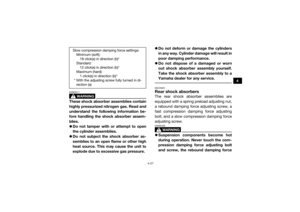
Slow compression damping force settings:
Minimum (soft):18 click(s) in direction (b)*
Standard: 12 click(s) in direction (b)*
Maximum (hard): 1 click(s) in direction (b)*
* With the adjusting screw fully turned in di- rection (a)
UB3D7AE0.book Page 27 Tuesday, November 7, 2017 9:38 AM
Page 66 of 188

4-28
4
adjusting screw or the oil reservoir with
your bare hand or skin until suspension
components have cooled.
Always adjust the shock absorber as-
semblies on the left and right side to the
same setting. Uneven adjustment can
cause poor handling and loss of stability,
which could lead to an accident. NOTICEECB00091Never turn an adjusting mechanism be-
yond the minimum and maximum settings. TIPAlthough the total number of clicks or turns of
a damping force adjusting mechanism may
not exactly match the following specifications
due to small differences in production, the ac-
tual number of clicks or turns always repre-
sents the entire adjusting range. To obtain a
precise adjustment, it would be advisable to check the number of clicks or turns of each
damping force adjusting mechanism and to
modify the specifications as necessary.
Spring preload
1. Loosen the locknut.
2. Turn the spring preload adjusting nut in direction (a) to increase the spring pre-
load and thereby harden the suspension,
and in direction (b) to decrease the spring
preload and thereby soften the suspen-
sion.
UB3D7AE0.book Page 28 Tuesday, November 7, 2017 9:38 AM
Page 67 of 188
4-29
4
TIPA special wrench can be obtained at a
Yamaha dealer to make this adjustment.
The spring preload setting is determined by
measuring distance A, shown in the illustra-
tion. The shorter distance A is, the higher
the spring preload; the longer distance A is,
the lower the spring preload. With each
complete turn of the adjusting nut, distance
A is changed by 1.5 mm (0.06 in).
3. Tighten the locknut to the specified
torque. NOTICE: Always tighten the
locknut against the adjusting nut, and
then tighten it to the specified torque.
[ECB00082]
1. Locknut
2. Spring preload adjusting nut
3. Special wrench
1
3
2
(a)
(b)
Spring preload setting: Minimum (soft):Distance A = 386.0 mm (15.20 in)
Standard: Distance A = 378.0 mm (14.88 in)
Maximum (hard): Distance A = 372.0 mm (14.65 in)1. Distance A
1
UB3D7AE0.book Page 29 Tuesday, November 7, 2017 9:38 AM
Page 68 of 188

4-30
4
Rebound damping force
Turn the rebound damping force adjusting
screw in direction (a) to increase the rebound
damping force and thereby harden the damp-
ing, and in direction (b) to decrease the re-
bound damping force and thereby soften the
damping.Compression damping force
Fast compression damping force
To increase the fast compression damping
force and thereby harden the compression
damping, turn the fast compression damping
force adjusting bolt in direction (a). To de-
crease the fast compression damping force
and thereby soften the compression damp-
ing, turn the adjusting bolt in direction (b).
Tightening torque:
Locknut:30 N·m (3.0 kgf·m, 22 lb·ft)1. Rebound damping force adjusting screw
1
(a)
(b)
Rebound damping setting:Minimum (soft):30 click(s) in direction (b)*
Standard: 14 click(s) in direction (b)*
Maximum (hard): 1 click(s) in direction (b)*
* With the adjusting screw fully turned in di- rection (a)
UB3D7AE0.book Page 30 Tuesday, November 7, 2017 9:38 AM
Page 69 of 188
4-31
4
Slow compression damping forceTo increase the slow compression damping
force and thereby harden the compression
damping, turn the slow compression damp-
ing force adjusting screw in direction (a). To
decrease the slow compression damping for-
ce and thereby soften the compression
damping, turn the adjusting screw in direction
(b).
1. Fast compression damping force adjusting boltFast compression damping force settings:Minimum (soft):2 turn(s) out from the fully turned in posi-
tion
Standard: 1 1/4 turn(s) out from the fully turned in
position
Maximum (hard): Adjusting bolt fully turned in
1
(a)
(b)
1. Slow compression damping force adjusting screw
1
(a)
(b)
UB3D7AE0.book Page 31 Tuesday, November 7, 2017 9:38 AM
Page 70 of 188

4-32
4
WARNING
EWB03500These shock absorber assemblies contain
highly pressurized nitrogen gas. Read and
understand the following information be-
fore handling the shock absorber assem-
blies.
Do not tamper with or attempt to open
the cylinder assemblies.
Do not subject the shock absorber as-
sembly to an open flame or other high
heat source. This may cause the unit to
explode due to excessive gas pressure.
Do not deform or damage the cylinders
in any way. Cylinder damage will result in
poor damping performance.
Do not dispose of a damaged or worn
out shock absorber assembly yourself.
Take the shock absorber assembly to a
Yamaha dealer for any service.
EBU31552Trailer hitch bracket and receiver
Slow compression damping force settings: Minimum (soft):18 click(s) in direction (b)*
Standard: 12 click(s) in direction (b)*
Maximum (hard): 1 click(s) in direction (b)*
* With the adjusting screw fully turned in di- rection (a)
1. Trailer hitch bracket
2. Receiver
1
2
UB3D7AE0.book Page 32 Tuesday, November 7, 2017 9:38 AM
Page 71 of 188
4-33
4
This vehicle is equipped with a trailer hitch
bracket and a 2" (5 cm) receiver for a stan-
dard trailer hitch. Trailer towing equipment
can be obtained at a Yamaha dealer. See
page 6-7 for loading information.EBU32952Auxiliary DC jack
This model has an auxiliary DC jack in the
dashboard. A 12-V accessory with the proper
plug, such as a radio or smartphone charger,
can be used when the engine is running and
the headlights are off.
1. Start the engine. (See page 6-2.)
2. Turn the headlights off. (See page 4-11.)
3. Open the auxiliary DC jack cap.
4. Turn the accessory off.
5. Insert the accessory power plug.
6. Turn the accessory on.TIP When inserting or removing the accessory
power plug, turn the accessory off.
When the auxiliary DC jack is not being
used, cover it with the cap.
1. Auxiliary DC jack cap
2. Auxiliary DC jack
21
Auxiliary DC jack maximum capacity:
10 A (120 W)
UB3D7AE0.book Page 33 Tuesday, November 7, 2017 9:38 AM
Page 72 of 188
4-34
4
NOTICEECB02250Do not use accessories requiring more
than the stated maximum capacity. Do-
ing so may overload the circuit and cau-
se the fuse to blow.
If accessories are used without the en-
gine running, the battery may discharge.
Do not use an automotive cigarette light-
er or other accessories with a plug that
gets hot, because the jack can be dam-
aged. UB3D7AE0.book Page 34 Tuesday, November 7, 2017 9:38 AM