2018 TOYOTA AVENSIS ECO mode
[x] Cancel search: ECO modePage 8 of 660

8
AVENSIS_OM_OM20C79E_(EE)
For your information
Please note that this manual applies to all models and all equipment, includ-
ing options. Therefore, you may find some explanations for equipment not
installed on your vehicle.
All specifications provided in this manual are current at the time of printing.
However, because of the Toyota policy of continual product improvement, we
reserve the right to make changes at any time without notice.
Depending on specifications, the vehicle shown in the illustrations may differ
from your vehicle in terms of equipment.
Both genuine Toyota and a wide variety of other spare parts and accessories
for Toyota vehicles are currently available on the market. Should it be deter-
mined that any of the genuine Toyota parts or accessories supplied with the
vehicle need to be replaced, Toyota recommends that genuine Toyota parts
or accessories, be used to replace them. Other parts or accessories of
matching quality can also be used. Toyota cannot accept any liability or guar-
antee spare parts and accessories which are not genuine Toyota products,
nor for replacement or installation involving such parts. In addition, damage
or performance problems resulting from the use of non-genuine Toyota spare
parts or accessories may not be covered under warranty.
The installation of an RF-transmitter system in your vehicle could affect elec-
tronic systems such as:
●Multiport fuel injection system/sequential multiport fuel injection system
●Cruise control system (if equipped)
●Anti-lock brake system
●SRS airbag system
●Seat belt pretensioner system
●Toyota Safety Sense (if equipped)
Be sure to check with any authorized Toyota retailer or Toyota authorized
repairer, or any reliable repairer for precautionary measures or special
instructions regarding installation of an RF-transmitter system.
Further information regarding frequency bands, power levels, antenna posi-
tions and installation provisions for the installation of RF-transmitters, is avail-
able on request at any authorized Toyota retailer or Toyota authorized
repairer, or any reliable repairer.
Main Owner’s Manual
Accessories, spare parts and modification of your Toyota
Installation of an RF-transmitter system
Page 31 of 660

311-1. For safe use
1
AVENSIS_OM_OM20C79E_(EE)
For safety and security
WARNING
Observe the following precautions.
Failure to do so may cause the driver’s floor mat to slip, possibly interfering
with the pedals while driving. An unexpectedly high speed may result or it may
become difficult to stop the vehicle. This could lead to an accident, resulting in
death or serious injury.
■ When installing the driver’s floor mat
● Do not use floor mats designed for other models or different model year
vehicles, even if they are Toyota Genuine floor mats.
● Only use floor mats designed for the driver’s seat.
● Always install the floor mat securely using the retaining hooks (clips) pro-
vided.
● Do not use two or more floor mats on top of each other.
● Do not place the floor mat bottom-side up or upside-down.
■ Before driving
●Check that the floor mat is securely
fixed in the correct place with all the
provided retaining hooks (clips). Be
especially careful to perform this check
after cleaning the floor.
● With the engine stopped and the shift
lever in P (Multidrive) or N (manual
transmission), fully depress each pedal
to the floor to make sure it does not
interfere with the floor mat.
Page 100 of 660

1002. Instrument cluster
AVENSIS_OM_OM20C79E_(EE)
*1: These lights turn on when the engine switch is turned to the “ON” position
(vehicles without smart entry & start system) or IGNITION ON mode (vehi-
cles with smart entry & start system) to indicate that a system check is
being performed. They will turn off after the engine is started, or after a few
seconds. There may be a malfunction in a system if a light does not turn
on, or if the lights do not turn off. Have the vehicle inspected by any autho-
rized Toyota retailer or Toyota authorized repairer, or any reliable repairer.
*2: The light flashes to indicate a malfunction.
Page 102 of 660

1022. Instrument cluster
AVENSIS_OM_OM20C79E_(EE)
*1: These lights turn on when the engine switch is turned to the “ON” position
(vehicles without smart entry & start system) or IGNITION ON mode (vehi-
cles with smart entry & start system) to indicate that a system check is
being performed. They will turn off after the engine is started, or after a few
seconds. There may be a malfunction in a system if a light does not turn
on, or if the lights do not turn off. Have the vehicle inspected by any autho-
rized Toyota retailer or Toyota authorized repairer, or any reliable repairer.
*2: The light flashes to indicate that the system is operating.
*3: The light turns on when the system is turned off.
*4: This light illuminates on the multi-information display.
*5: For vehicles with the color display, this light illuminates on the multi-infor-
mation display.
*1
(If equipped)
Auto P-off indicator
( P. 231)
*1, 3
(If equipped)
PCS warning light
( P. 262)
*4
(If equipped)
Shift position indicator
( P. 222)
*5
(If equipped)
“SPORT” indicator
( P. 220)
*4
(If equipped)
Shift position indicator
( P. 222)
Parking brake indicator
( P. 230)
*1, 4
(If equipped)
Gear Shift Indicator
( P. 226)(If equipped)
Low outside
temperature indicator
( P. 107)
“PASSENGER
AIRBAG” indicator
(on the center
panel) ( P. 5 2 )
Page 103 of 660

1032. Instrument cluster
2
Instrument cluster
AVENSIS_OM_OM20C79E_(EE)
■Eco Driving Indicator Light (if equipped)
● The vehicle is being driven in “SPORT” mode (P. 220)
● If equipped, the paddle shift switch is operated while the shift position is D
● The vehicle speed is approximately 130 km/h (80 mph) or higher.
During Eco-Friendly acceleration (Eco-
driving), Eco Driving Indicator Light will
turn on. When the acceleration exceeds
Zone of Eco driving, and when the vehicle
is stopped, the light turns off.
Eco Driving Indicator Light will not operate
in the following conditions:
● The shift lever is in anything other than
D.
WARNING
■ If a safety system warning light does not come on
Should a safety system light such as ABS and SRS airbag warning light not
come on when you start the engine, this could mean that these systems are
not available to help protect you in an accident, which could result in death
or serious injury. Have the vehicle inspected by any authorized Toyota
retailer or Toyota authorized repairer, or any reliable repairer immediately if
this occurs.
Page 106 of 660

1062. Instrument cluster
AVENSIS_OM_OM20C79E_(EE)
Odometer and trip meter display
Displays the following items.
●Odometer
Displays the total distance the vehicle has been driven.
●Trip meter
Displays the distance the vehicle has been driven since the meter was
last reset. Trip meters A and B can be used to record and display differ-
ent distances independently.
●Maintenance required information (1WW and 2WW engines)
Displays the remaining distance until the engine oil should be changed.
If “-” is displayed before distance, it means oil maintenance is overdue.
Have the engine oil changed by any authorized Toyota retailer or Toyota
authorized repairer, or any reliable repairer.
• Displays the maintenance required information when the engine
switch is turned to the “ON” position (vehicles without smart entry &
start system) or in IGNITION ON mode (vehicles with smart entry &
start system).
• Maintenance required information reset method (P. 459)
●Stop & Start system operation time (1WW and 2WW engines
with monochrome display)
Displays the amount of time the engine was stopped due to operation of
the Stop & Start system during the current trip.
●Stop & Start system total operation time (1WW and 2WW
engines with monochrome display)
Displays the total amount of time that the engine has been stopped due
to operation of the Stop & Start system since the system was last reset.
●Stop & Start system operation time (1WW and 2WW engines
with color display)
Displays the elapsed time after the engine is stopped until it is re-started
by the Stop & Start system.
●Instrument panel light control display (vehicles with monochrome
display)
Displays the meter light control display.
Engine coolant temperature gauge
Displays the engine coolant temperature.
7
8
Page 117 of 660

117
2
2. Instrument cluster
Instrument cluster
AVENSIS_OM_OM20C79E_(EE)
Fuel consumption information
Press the “CAR” button, and then select “Trip information” or “Past
record” on the screen.
Average vehicle speed
Cruising range
Previous fuel consumption per
minute
Current fuel consumption
Reset the trip information data
Elapsed time
“Past record” screen appears
Average fuel consumption for the past 15 minutes is divided by color
into past averages and averages attained since the engine switch was
last turned to the “ON” position (vehicles without smart entry & start
system) or IGNITION ON mode (vehicles with smart entry & start sys-
tem). Use the displayed average fuel consumption as a reference.
These images are examples only, and may vary slightly from actual
conditions.
: If equipped
The fuel consumption information can be displayed on the navi-
gation system or multimedia system screen.
Display the trip information or past record screen
Trip information
1
2
3
4
5
6
7
Page 137 of 660

1373-2. Opening, closing and locking the doors
3
Operation of each component
AVENSIS_OM_OM20C79E_(EE)■
Setting and canceling the functions (vehicles without naviga-
tion system or multimedia system)
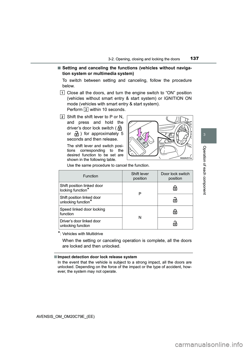
To switch between setting and canceling, follow the procedure
below.
Close all the doors, and turn the engine switch to “ON” position
(vehicles without smart entry & start system) or IGNITION ON
mode (vehicles with smart entry & start system).
Perform within 10 seconds.
Shift the shift lever to P or N,
and press and hold the
driver’s door lock switch (
or ) for approximately 5
seconds and then release.
The shift lever and switch posi-
tions corresponding to the
desired function to be set are
shown in the following table.
Use the same procedure to cancel the function.
*: Vehicles with Multidrive
When the setting or canceling operation is complete, all the doors
are locked and then unlocked.
■Impact detection door lock release system
In the event that the vehicle is subject to a strong impact, all the doors are
unlocked. Depending on the force of the impact or the type of accident, how-
ever, the system may not operate.
1
2
2
FunctionShift lever
positionDoor lock switch
position
Shift position linked door
locking function
*PShift position linked door
unlocking function
*
Speed linked door locking
function
NDriver’s door linked door
unlocking function