Page 65 of 324

63
Load space cover,
blind (SW)
When sharp deceleration occurs, objects
placed on the load space cover can turn
into projectiles.
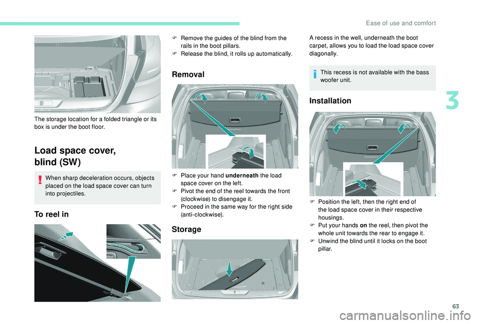
To reel inRemoval
Storage
The storage location for a folded triangle or its
box is under the boot floor. F
R
emove the guides of the blind from the
rails in the boot pillars.
F
R
elease the blind, it rolls up automatically.
F
P
lace your hand underneath the load
space cover on the left.
F
P
ivot the end of the reel towards the front
(clockwise) to disengage it.
F
P
roceed in the same way for the right side
(anti-clockwise). A recess in the well, underneath the boot
carpet, allows you to load the load space cover
diagonally.
This recess is not available with the bass
woofer unit.
Installation
F Position the left, then the right end of the load space cover in their respective
housings.
F
P
ut your hands on the reel, then pivot the
whole unit towards the rear to engage it.
F
U
nwind the blind until it locks on the boot
pillar.
3
Ease of use and comfort
Page 178 of 324

176
Trailers with LED lamps are not
compatible with the wiring harness of this
device.
To know the Technical data , and, in
particular, the towable weights for your
vehicle, refer to the corresponding section.
To ensure complete safety while driving
with a To w b a r d e v i c e , refer to the
corresponding section.
Fitting the towball
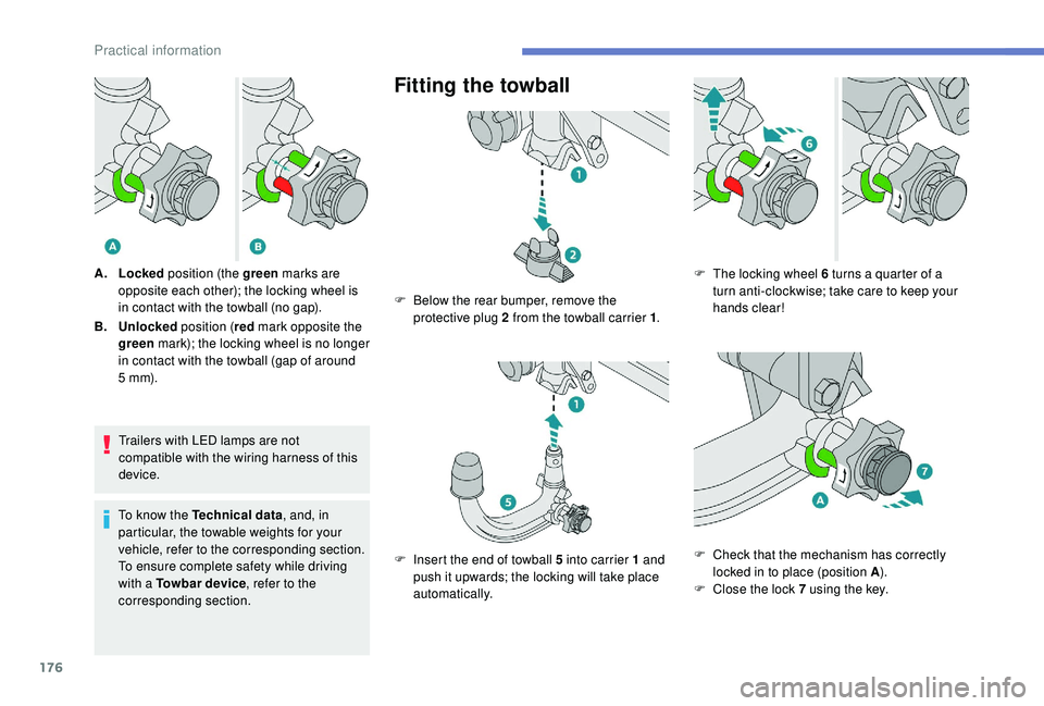
A. Locked position (the green marks are
opposite each other); the locking wheel is
in contact with the towball (no gap).
B. Unlocked position (red mark opposite the
green mark); the locking wheel is no longer
in contact with the towball (gap of around
5
m m). F
B
elow the rear bumper, remove the
protective plug 2 from the towball carrier 1 .
F
I
nsert the end of towball 5 into carrier 1 and
push it upwards; the locking will take place
automatically. F
T he locking wheel 6 turns a quarter of a
turn anti-clockwise; take care to keep your
hands clear!
F
C
heck that the mechanism has correctly
locked in to place (position A ).
F
C
lose the lock 7 using the key.
Practical information
Page 179 of 324
177
Removing the towball
F Always remove the key. The key cannot be removed when the lock is open.
F
C
lip the cap onto the lock.
F
R
emove the protective cover from the
towball.
F
A
ttach the trailer to the towball.
F
A
ttach the cable on the trailer to the safety
eye 4 on the carrier.
F
I
nsert the trailer plug and give it a quarter
turn to connect it to socket 3 of the carrier. F
G ive a quarter turn and pull the trailer plug
to disconnect it from socket 3 of the carrier.
F
D
etach the cable on the trailer from the
safety eye 4 on the carrier.
F
D
etach the trailer from the towball.
F
R
efit the protective cover to the towball.
F
R
emove the cap from the lock and press it
onto the head of the key. F
I nsert the key into the lock 7
.
F O pen the lock using the key.
F
H
old towball 5 firmly in one hand; using the
other hand, pull and turn locking wheel 6
fully in a clockwise direction; do not release
the locking wheel.
7
Practical information
Page 193 of 324

191
Access to the AdBlue® tank
via the boot
Filling the AdBlue® tank is an operation
included in every routine ser vice on your
vehicle by a PEUGEOT dealer or a qualified
workshop.
Nevertheless, given the capacity of the tank, it
may be necessary to top up the fluid between
ser vices, as soon as an alert (warning lamps
and a message) indicates it.
You can go to a PEUGEOT dealer or a qualified
workshop.
If you intend to do the topping-up yourself,
read the following procedure carefully.
The supply in a non-drip bottle simplifies
topping up.
F
S
witch off the ignition and remove the key. F
W
orking inside the boot, lift the carpet and
then, depending on the equipment, lift out
the spare wheel and/or the storage well.
F
W
ithout pressing, turn the black cap a
quarter turn anti-clockwise and lift it off.
F
T
urn the blue cap anti-clockwise.
F
O
btain non-drip bottles of AdBlue
®. After
first checking the use-by date, carefully
read the instructions for use on the label
before pouring the contents of the bottle into
your vehicle's AdBlue
® tank.
F
A
fter filling, per form the same operations in
reverse order.
With subwoofer
- Carefully disengage the wiring harness from its housing to give a little more free cable
length.
-
U
ndo the central nut and remove the
fastener (nut and bolt).
F
P
lace the subwoofer to the side of the boot.
7
Practical information
Page 194 of 324

192
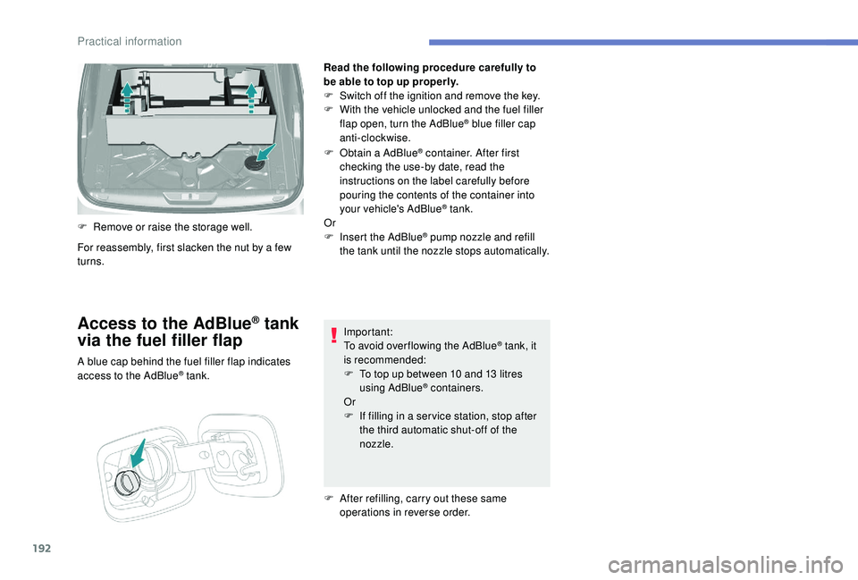
Read the following procedure carefully to
be able to top up properly.
F
S
witch off the ignition and remove the key.
F
W
ith the vehicle unlocked and the fuel filler
flap open, turn the AdBlue
® blue filler cap
anti-clockwise.
F
O
btain a AdBlue
® container. After first
checking the use-by date, read the
instructions on the label carefully before
pouring the contents of the container into
your vehicle's AdBlue
® tank.
Or
F
I
nsert the AdBlue
® pump nozzle and refill
the tank until the nozzle stops automatically.
Important:
To avoid over flowing the AdBlue
® tank, it
i
s recommended:
F
T
o top up between 10 and 13
litres
using AdBlue
® containers.
Or
F
I
f filling in a ser vice station, stop after
the third automatic shut-off of the
nozzle.
F
A
fter refilling, carry out these same
operations in reverse order.
Access to the AdBlue® tank
via the fuel filler flap
A blue cap behind the fuel filler flap indicates
access to the AdBlue® tank.
For reassembly, first slacken the nut by a few
turns. F
R
emove or raise the storage well.
Practical information
Page 202 of 324

200
Removing the pipe and
cartridge
Be careful of fluid discharge.
The expiry date of the fluid is indicated on
the cartridge.
The sealant cartridge is designed for
single use; it must be replaced even if only
partly used.
After use, do not discard the cartridge into
the environment, take it to an authorised
waste disposal site or a PEUGEOT dealer.
Do not forget to obtain a new sealant
cartridge, available from PEUGEOT
dealers or from a qualified workshop.
Checking/adjusting tyre
pressures
You can also use the compressor,
without injecting sealant, to check and, if
necessary, adjust the tyre pressures.F
T
urn selector A to the "Air"
position.
F
U
ncoil the white pipe G fully.
F
C
onnect the pipe to the tyre
valve.
F
C
onnect the compressor's electric plug to
the vehicle's 12 V socket.
Only the 12 V socket located at the front
of the vehicle can be used.
F
S
tart the vehicle and leave the engine
running.
F
T
urn the pipe assembly 2 to the left until it
comes into contact with the unit.
F
D
isconnect the connector 1 from the
cartridge by turning it a quarter turn anti-
clockwise.
F
P
ull the pipe assembly 2 out slightly, then
disconnect the connector 3 from the air
intake pipe by turning it a quarter turn anti-
clockwise. F
R
emove the pipe assembly 2
.
F
K
eep the compressor vertical.
F
U
nscrew the cartridge 4 from the bottom.
To fit the new cartridge and new pipe, carry out
these operations in reverse order.
The tyre inflation pressures are given on
this label.
In the event of a breakdown