Page 305 of 441

Wiper deicer switch (if so equipped)5-224 Features and controls
5
N00523501277
N00584400027
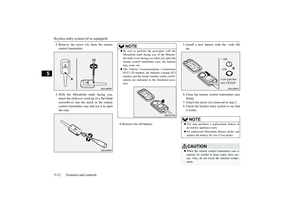
The electric rear window defogger switch canbe operated when the engine is running.
NOTE
The rear window wipe
r will automatically
perform several conti
nuous operations if the
selector lever is put in the “R” position whilethe windshield wipers
or the rear window
wiper is operating.(a
utomatic operation
mode)After the automatic operation, the rear win-dow wiper will stop operating if the knob isin the “OFF” position. If the knob is in the“INT” position, the re
ar window wiper will
return to the intermittent operation.It is possible to set the rear window wiper toperform the automatic operation only if theselector lever is put in the “R” position whilethe rear window wiper
is operating with the
knob in the “INT” position.See your authorized Mitsubishi Motorsdealer for details.If the knob is in the “OFF” position, turn theknob to the “INT” position twice quickly tooperate the rear window
wiper continuously.
(continuous ope
ration mode)
Turn the knob to the “OFF” position to stopthe rear window wipe
r continuous operation.
The wiper intermittent
operation time can be
adjusted.See your authorized Mitsubishi Motorsdealer for details.For vehicles equipped with the SmartphoneLink Display Audio, adjustments can bemade using screen ope
rations. For further
details, refer to the se
parate owner’s manual.
The washer fluid reservoir is located in theengine compartment.Check the fluid level re
gularly and refill if
necessary. (Refer to
“Washer fluid” on page
9-12.)
Precautions to observe when using wipers and washers
CAUTIONIf the washer is used
in cold weather, the
washer fluid sprayed onto the glass mightfreeze, blocking your vi
ew. Heat the glass
with the defroster befo
re using the washer.
NOTE
Do not use the wipers when the windshield isdry. This could scratch the glass and wear thewiper blades prematurely.Before using the wipe
rs in cold weather,
check to be sure that the wiper blades are notfrozen to the windshield or rear window.Using the wipers while the blades are frozencould cause the wiper motor to burn out.NOTE
If the moving wipers be
come blocked part-
way through a sweep by ic
e or other deposits
on the glass, the wipers may temporarily stopoperating to prevent the motor from over-heating. In this case, park the vehicle in asafe place, turn the ignition switch to the“OFF” position or put the operation mode inOFF, and then remove
the ice or other depos-
its.Because the wipers will start operating againafter the wiper motor cools down, check thatthe wipers operate
before using them.
Avoid using the washer for more than 20 sec-onds at a time. Do not operate the washerwhen the washer fluid reservoir is empty orthe pump may fail.During cold weather, add a recommendedwasher solution that will not freeze in thewasher fluid reservoir. Otherwise the washermay not work or may be damaged.Replace the wiper blades when they areworn. Use the proper size replacementblades. For further info
rmation, please con-
tact your authorized
Mitsubishi Motors
dealer.
Wiper deicer switch
(if so
equipped)
BK0249100US.book 224 ページ 2017年5月10日 水曜日 午前8時49分
Page 306 of 441

Electric rear window defogger switch
Features and controls 5-225
5
When the front wipers have frozen to thewindshield at the parked
positions, turning on
this switch will heat the windshield to makethe wipers operable. Pr
ess the electric rear
window defogger switch and the deicer willoperate.
N00523701497
The rear window defogger can be used whenthe engine is running.The indicator light (A) will come on whenyou press the electric rear window defoggerswitch. Electric current will flow through theheating wires on the rear window to helpclear away moisture or frost.After approximately 15 to 20 minutes ofoperation, the system wi
ll shut off automati-
cally.To switch the defogger OFF before 15 to 20minutes have passed,
press the switch again.
The indicator light will
go out and the defog-
ger will turn off.If you need the defogger for more than 15 to20 minutes, press the switch again. This willadd 15 to 20 more minutes.
NOTE
The wiper deicer is
activated/de
activated,
depending on the operation of the rear win-dow defogger. Refer to
“Electric rear win-
dow defogger switch
” on page 5-225.
Electric rear window defog-ger switch
CAUTIONThe rear window defogge
r is not designed to
melt snow. Remove
any snow manually
before using the rear window defogger.Use the rear window de
fogger only after the
engine has started and
is running. Be sure to
turn the defogger swit
ch off immediately
after the window is cl
ear to save on battery
power.Do not place stickers,
tape, or other items
that are attached with adhesive over the gridwires on the rear window.When cleaning the inside
rear window, use a
soft cloth and wipe lightly over the gridwires.NOTE
If your vehicle is equi
pped with heated out-
side rearview mirror, mist can also beremoved from the outside rearview mirrorswhen the rear window defogger switch ispressed. (Refer to “Hmirror” on page 5-63.)On vehicles equipped w
ith the wiper deicer,
when the rear window defogger switch ispushed, the windshield
becomes warm and
the wipers become operable. (Refer to“Wiper deicer switch” on page 5-224.)
BK0249100US.book 225 ページ 2017年5月10日 水曜日 午前8時49分
Page 307 of 441

Heated steering wheel sw
itch (if so equipped)
5-226 Features and controls
5
N00589100032
The heated steering wheel contains internalheaters in the rim. Heating areas are shown inthe illustration.
: Heating area
The heated steering wheel can be operatedwhen the ignition switch or operation mode isin ON.To turn on the heated steering wheel, push theheated steering wheel switch. The heatedsteering wheel will ope
rate for approximately
30 minutes and then it
will automatically turn
off.The indicator light (A) will illuminate whilethe heated steering wheel is operating.
It is possible to change the setting to makethe rear window def
ogger operate automati-
cally when ambient temperature becomeslow while the engine is running, even if youdo not push the rear window defoggerswitch.It operates automatica
lly only once after
turning the ignition switch to the “ON” posi-tion or putting the ope
ration mode in ON.
If you choose this setti
ng, the heated outside
rearview mirror (if so
equipped) and wiper
deicer (if so equippe
d) will also operate
automatically at the same time.For further information, please contact yourauthorized Mitsubishi Motors dealer.On vehicles equippe
d with the Smartphone
Link Display Audio, sc
reen operations can
be used to make the adjustment.Refer to the separate
owner’s manual for
details.NOTE
Heated steering wheel switch
(if so equipped)
Persons who are unable
to feel tempera-
ture change or skin
pain due to age, ill-
ness, injury, medicati
on, fatigue or other
physical conditions or
who have sensitive
skin may suffer burns when using theheated steering wheel. To reduce the riskof burns, people with such conditions mustuse care when using the heated steeringwheel.CAUTIONIf water or any other li
quid is spilled on the
steering wheel, allow it to dry thoroughlybefore attempting to use the heated steeringwheel. Turn the heated steering wheel offimmediately if it appe
ars to be malfunction-
ing during use.Also be aware that us
ing the heated steering
wheel with the engine off may run the bat-tery down.
BK0249100US.book 226 ページ 2017年5月10日 水曜日 午前8時49分
Page 308 of 441

Horn switch
Features and controls 5-227
5
N00523801195
To honk the horn, press around the “ ” markon the steering wheel.
N00563701183
The Link System takes control of the devicesconnected via the USB i
nput terminal or the
Bluetooth
® device; the system allows the
connected device to be operated by using theswitches in the vehicl
e or voice commands.
For details on how to operate, refer to “USBinput terminal” on page 5-227 and the sepa-rate owner’s manual.Bluetooth
® is a registered trademark of
BLUETOOTH SIG, INC.
N00566701168
You can connect your USB memory device oriPod
* to play music files stored in the USB
memory device or iPod.This section explains how to connect andremove a USB memory device or iPod.Refer to the separate owner’s manual fordetails on the types of
connectable devices
and supported files, and how to play musicfiles.*: “iPod” is a registered trademark of AppleInc. in the United Stat
es and other countries.
N00566801156
1. Park your vehicle in a safe place and turnthe ignition switch to the “LOCK” posi-tion or put the operation mode in OFF.
2. Open the USB input
terminal cover (A) in
the floor console box.3. Connect a commercia
lly available USB
connector cable (C) to the USB memorydevice (B).
Horn switch Link System
USB input terminal How to connect a USB memory device
Ty p e 1Ty p e 2
BK0249100US.book 227 ページ 2017年5月10日 水曜日 午前8時49分
Page 309 of 441

USB input terminal5-228 Features and controls
5
4. Connect the USB connector cable (C) tothe USB input terminal (D).5. To remove the USB connector cable, turnthe ignition switch to the “LOCK” posi-tion or put the operation mode in OFFfirst and perform the installation steps inreverse.
N00566901199
1. Park your vehicle in
a safe place and turn
the ignition switch to the “LOCK” posi-tion or put the operation mode in OFF.2. Open the USB input terminal cover (A) inthe floor console box.3. Connect the connector cable to the iPod.
4. Connect the connector cable (B) totheUSB input terminal (C).5. To remove the connect
or cable, turn the
ignition switch to the “LOCK” position orput the operation mode in OFF first andperform the installation steps in reverse.
CAUTIONKeep the lid of the floor console box closedwhile driving the vehicle. A lid or the con-tents of the floor console box could other-wise cause injuries.NOTE
Do not connect the US
B memory device to
the USB input term
inal directly.
The USB memory devi
ce may be damaged.
When closing the floor
console box, be care-
ful not to trap the USB connector cable.
How to connect an iPod
NOTE
Use a genuine connector
cable from Apple
Inc.
Ty p e 1Ty p e 2
CAUTIONKeep the lid of the floor console box closedwhile driving the vehicle. A lid or the con-tents of the floor console box could other-wise cause injuries.NOTE
When closing the floor
console box, be care-
ful not to trap the connector cable.
BK0249100US.book 228 ページ 2017年5月10日 水曜日 午前8時49分
Page 310 of 441
Sun visors
Features and controls 5-229
5
N00524601363
Pull the sun visor downward (1) to reducefront glare while driving. To reduce sideglare, turn the visor to the side (2).
A vanity mirror is fitted to the back of the sunvisor.Operating the lid of the vanity mirror willautomatically turn on the mirror light (A).
Cards can be slipped into the holder (B) onthe sun visor.
Sun visors
Vanity mirror
CAUTIONIf the lid of vanity mirror with light is keptopen for prolonged periods
of time, the vehi-
cle’s battery will be discharged.
Card holder
BK0249100US.book 229 ページ 2017年5月10日 水曜日 午前8時49分
Page 311 of 441

12 V power outlets5-230 Features and controls
5
N00525001683
To use a “plug-in” type
accessory, open the
cover or remove the ca
p, and insert the plug
in the power outlet.
Accessories can be operated when the igni-tion switch or the operation mode is in ON orACC.
Accessories can be oper
ated in all ignition
switch positions or all operation modes.
12 V power outlets
CAUTIONBe sure to use a “plug-in” type accessoryoperating at 12 V and at 120 W or less.When using more than one socket at thesame time, make sure the total power con-sumption of the electrical accessories doesnot exceed 120 W at 12 V.Also be aware that
using electronic equip-
ment with the engine
off may run the battery
down.When the power outlet is not in use, be sureto close the power outle
t cover or replace the
cap. This will prevent the power outlet frombecoming clogged and short circuiting.NOTE
Three 12V power
outlets can be used simul-
taneously.
Type 1 Floor console
Ty p e 2 Floor console boxRear
BK0249100US.book 230 ページ 2017年5月10日 水曜日 午前8時49分
Page 312 of 441

HomeLink® Wireless Control System (if so equipped)
Features and controls 5-231
5
N00554301040
HomeLink
® Wireless Control System is a
registered trademark of Gentex Corporation.HomeLink
® provides a convenient way to
replace up to 3 hand-held radio-frequency(RF) transmitters used
to activate devices
such as gate operators, garage door openers,entry door locks, securi
ty systems, even home
lighting. Addi
tional HomeLink
® information
can be found at www.homelink.com,www.youtube.com/HomeL
inkGentex, or by
calling the toll-free HomeLink
®-Hotline at 1-
800-355-3515.
N00584600029
Some garage door openers manufacturedafter 1995 have “rollin
g code protection”.
To program a garage door openerequipped with “rolli
ng code protection”;
you will need to access the garage dooropener motor to press the motor’s “Learn”a ladder and another person to assist you.It is recommended that a new battery beplaced in the hand-held transmitter of thedevice being programmed to HomeLink
®
for quicker training and accurate trans-mission of the radio-frequency signal.
HomeLink
® Wireless Con-
trol System
(if so equipped)
Do not use HomeLink
® with any garage
door opener that lacks safety stop andreverse features as re
quired by U.S. Fed-
eral Regulations.
A garage door opener
which cannot detect an object in the pathof a closing garage d
oor and then auto-
matically stop and reverse, does not meetcurrent U.S. Federal Regulations. Using agarage door opener wi
thout these features
increases the risk of serious injury ordeath.
During programming, your garage dooror gate may open or cl
ose. Make sure that
people and ob
jects are clear of the garage
door or gate that you are programming.NOTE
Once HomeLink
® is programmed, retain the
original transmitter for future programmingprocedures (for exam
ple, new vehicle pur-
chases). Upon sale of the vehicle, the pro-grammed HomeLink
® buttons should be
erased for security purposes. Refer to“Cleaning the programmed information” onpage 5-235.You can program a maximum of 3 devices.To change or replace any of the 3 devicesafter it has been in
itially programmed, you
must first erase the current settings.See “Cleaning the programmed information”on page 5-235 or “Reprogramming a singleHomeLink
® button” on page 5-235.
WA R N I N G
1-
HomeLink
® button 1
2-
HomeLink
® button 2
3-
HomeLink
® button 3
Before programming Home-Link
®
BK0249100US.book 231 ページ 2017年5月10日 水曜日 午前8時49分