2018 MERCEDES-BENZ SLC ROADSTER spare tire
[x] Cancel search: spare tirePage 265 of 298
To avoid hazardous situations:
Rnever install snow chains to the front
wheels
Ralwaysinstall snow chains in pairs to the
rear wheels.
For safety reasons, Mercedes-Benz recom-
mends that you only use snow chains that have
been specially approved for your vehicle by
Mercedes-Benz,ora re ofacorresponding
standard of quality. For more information,
please contact aqualified specialist workshop.
If you inten dtomount snow chains, please bear
the following points in mind:
RSnow chains may not be mounted on all
wheel/tire combinations. Permissible wheel-
tire combinations (
Ypage 284).
ROnly use snow chains when driving on roads
completely covered by snow. Remove the
snow chains as soon as possible when you
come to aroad that is not snow-covered.
RLocal regulations may restrict the use of snow
chains. Observe the appropriate regulations if
you wish to mount snow chains.
RDo not exceed the maximum permissible
speed of 30 mph (50 km/h).
You may wish to deactivate ESP
®when pulling
away with snow chains installed (Ypage 60).
You can thereby allow the wheels to spin in a
controlled manner ,achieving an increased driv-
ing force (cutting action).
Information about driving with an emergency
spare wheel (
Ypage 285).
Tire pressure
Tire pressur especifications
Important safety notes
GWARNING
Underinflated or overinflated tires pose the
following risks:
Rthe tires may burst, especially as the load
and vehicle speed increase.
Rthe tires may wear excessively and/or
unevenly, which may greatly impair tire
traction.
Rthe driving characteristics, as well as steer-
ing and braking, may be greatly impaired.
There is arisk of an accident.
Follow recommended tire inflation pressures
and check the pressure of all the tires includ-
ing the spare wheel:
Rmonthly, at least
Rif the load changes
Rbefore beginning along journey
Runder different operating conditions, e.g.
off-road driving
If necessary, correctt he tire pressure.
The data on the Tire and Loading Information
placard and tire pressure table shown here are
examples. Tire pressure specification sare vehi-
cle-specific and may deviate from the data
shown here. The tire pressure specifications
that are valid for your vehicle can be found on
the Tire and Loading Information placard and
tire pressure table on the vehicle.
General notes
The recommended tire pressures for the tires
mounted at the factor ycan be found on the
labels described here.
Operation with an emergency sparew heel:
information on operation with an emergency
spare wheel can be found in the general notes in
the "Emergency spare wheel" section
(
Ypage 286).
Further information on tire pressures can be
obtained at aqualified specialist workshop.
Tirep ressure263
Wheels and tires
Z
Page 268 of 298
Avoidtire pressures thata retoo high in al lthe
tires, including the spare wheel.
Overinflated tire smay:
Rincrease the braking distance
Radversel yaffect handling
Rwear excessivel yand/or unevenly
Rhave an adverse effect on rid ecomfort
Rbe more susceptibl etodamage
Maximum tire pressures
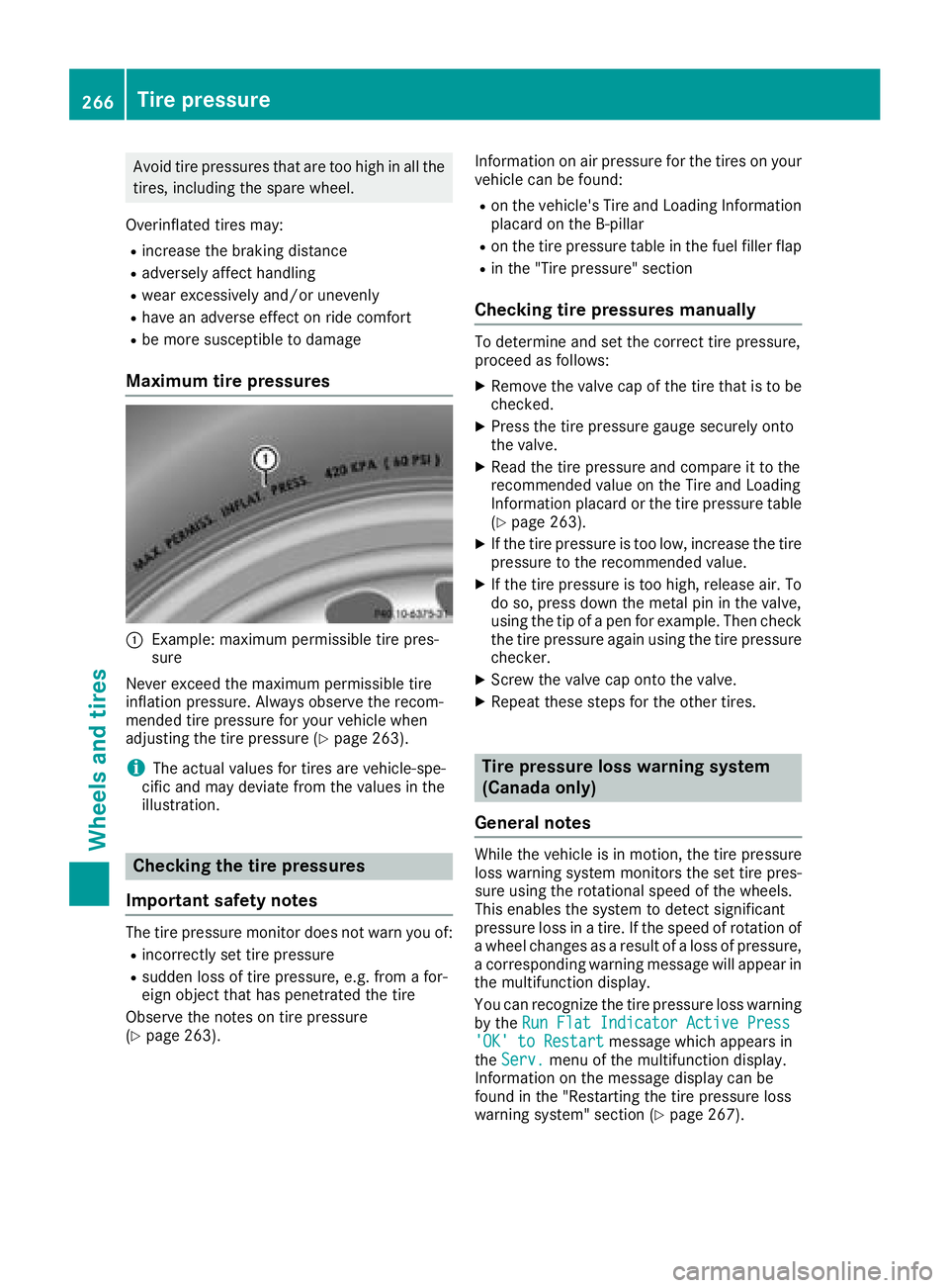
:Example: maximu mpermissibl etire pres-
sure
Never exceed the maximu mpermissibl etire
inflation pressure. Alway sobserve the recom-
mended tire pressure for your vehicl ewhen
adjusting the tire pressure (
Ypage 263).
iThe actual values for tire sarevehicle-spe-
cifi cand mayd eviate from the values in the
illustration.
Checkin gthe tire pressures
Important safety notes
The tire pressure monitor does not warn yo uof:
Rincorrectly set tire pressure
Rsudden loss of tire pressure, e.g .from afor-
eign object thath aspenetrated the tire
Observ ethe notes on tire pressure
(
Ypage 263). Informatio
nonairpressure for the tire sonyour
vehicl ecan be found:
Ron the vehicle's Tire and Loading Information
placard on the B-pillar
Ron the tire pressure table in the fuel fille rflap
Rin the "Tire pressure" section
Checkin gtire pressuresm anually
To determine and set the correct tire pressure,
proceedasfollows:
XRemove the valve cap of the tire thati stobe
checked.
XPress the tire pressure gaug esecurel yonto
the valve.
XRead the tire pressure and compar eittothe
recommende dvalue on the Tire and Loading
Informatio nplacard or the tire pressure table
(
Ypage 263).
XIf the tire pressure is too low, increase the tire
pressure to the recommende dvalue.
XIf the tire pressure is too high, release air. To
do so, press down the meta lpinin the valve,
using the tip of apen for example. The ncheck
the tire pressure agai nusing the tire pressure
checker.
XScrew the valve cap onto the valve.
XRepeat thes estepsf or the othe rtires.
Tire pressure loss warning system
(Canada only)
General notes
While the vehicl eisinmotion, the tire pressure
loss warning system monitors the set tire pres-
sure using the rotational speed of the wheels.
Thi senables the system to detect significant
pressure loss in atire .Ift he speed of rotatio nof
aw heel changesasa resultofa loss of pressure,
ac orresponding warning message will appear in
the multifunctio ndisplay.
Yo uc an recognize the tire pressure loss warning
by the Run FlatI ndicator Active Press
'OK'toRestartmessage which appear sin
the Serv.menu of the multifunctio ndisplay.
Informatio nonthe message display can be
found in the "Restarting the tire pressure loss
warning system "sectio n(
Ypage 267).
266Tire pressure
Wheel sand tires
Page 281 of 298
Speed rating
The speed rating is part of the tire identification.It specifies the speed range for which the tire is
approved.
GVW (Gross Vehicle Weight)
The gross vehicle weight includes the weight of the vehicle including fuel, tools, the spare wheel,
accessories installed, occupants, luggage and
the drawbar noseweight, if applicable. The gross
vehicle weight must not exceed the gross vehi-
cle weight rating GVWR as specified on the vehi- cle identification plate on the B-pillar on the
driver's side.
GVWR (Gross Vehicle Weight Rating)
The GVWR is the maximum permissible gross
weight of afully loaded vehicle (the weight of the
vehicle including all accessories, occupants,
fuel, luggage and the drawbar noseweight, if
applicable). The gross vehicle weight rating is
specified on the vehicle identification plate on
the B-pillar on the driver's side.
Maximu mloaded vehicle weight
The maximum weight is the sum of:
Rthe curb weight of the vehicle
Rthe weight of the accessories
Rthe load limit
Rthe weight of the factory installed optional
equipment
Kilopascal (kPa)
Metric unit for tire pressure. 6.9 kPa corre-
sponds to 1psi. Another unit for tire pressure is
bar. 100 kilopascals (kPa) are the equivalent of
1b ar.
Load index
In addition to the load-bearing index, the load
index may also be imprinted on the sidewallo f
the tire. This specifies the load-bearing capacity
more precisely.
Curb weight
The weight of avehicle with standard equipment
including the maximum capacity of fuel, oil and
coolant. It also includes the air-conditioning sys-
tem and optional equipment if these are instal-
led in the vehicle, but does not include passen-
gers or luggage.
Maximu mload rating
The maximum load rating is the maximum per-
missible weight in kilograms or lbs for which a
tire is approved.
Maximu mpermissible tire pressure
Maximum permissible tire pressure for one tire.
Maximu mload on one tire
Maximum load on one tire. This is calculated by
dividing the maximum axle load of one axle by
two.
PSI (pounds per squarei nch)
Astandard unit of measure for tire pressure.
Aspect ratio
Relationship between tire height and tire width
in percent.
Tire pressure
This is pressure inside the tire applying an out-
ward force to each square inch of the tire's sur-
face. The tire pressure is specified in pounds per
square inch (psi), in kilopascal (kPa) or in bar.
The tire pressure should only be corrected when the tires are cold.
Cold tire pressure
The tires are cold:
Rif the vehicle has been parked with the tires
out of direct sunlight for at least three hours
and
Rif the vehicle has not been driven further than
1m ile (1.6 km)
Tread
The part of the tire that comes into contact with
the road.
Bead
The tire bead ensures that the tire sits securely
on the wheel. There are several steel wires in the
bead to prevent the tire from coming loose from
the wheel rim.
Sidewall
The part of the tire between the tread and the
bead.
All about wheelsa nd tires279
Wheels and tires
Z
Page 286 of 298
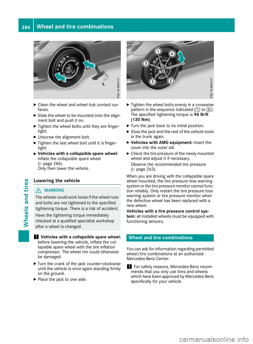
XClean thewheel and wheel hub contact sur-
faces.
XSlid ethe wheel to bemounte dontot he align-
men tbolt and push iton.
XTighte nthe wheel boltsuntilthey are finger-
tight.
XUnscrew th ealignmen tbolt.
XTighte nthe last wheel boltuntil it is finger-
tight.
XVehicles with acollapsible spa rewheel:
inflate th ecollapsible sparewheel
(
Ypage 286).
Only then lower th evehicle .
Lowering th evehicle
GWAR NING
The wheelsc ouldwork looseift hewheel nuts
and boltsare no ttightened to th especifie d
tightening torque. Thereisar iskofa cciden t.
Hav ethe tightening torque immediately
checked at aqualified specialist workshop
after awheel ischanged.
!Vehicles with acollapsible spa rewheel:
before lowering th evehicle ,inflate th ecol-
lapsible sparewheelwiththe tirei nflation
compressor. The wheel rim could otherwise
be damaged.
XTurn th ecrank of th ejackc ounter-clock wise
unt ilth ev ehicle is once again standing firmly
on th eground.
XPlacet hejacktoo neside.
XTighte nthe wheel boltse venlyinac rosswise
pattern inthes equenc eindicated (: toA).
The specifie dtightening torque is 96lb-ft
(1 30 Nm) .
XTurn th ejackb ack to its initial position.
XStow th ejac ka nd th erestoft hevehicle tools
in thet runk again.
XVehicles with AMG equipment: insert the
cover int othe outer sill.
XCheckt hetirep ressureoft henewly mounted
wheel and adjust it if necessary.
Observ ethe recommended tir epressure
(
Ypage 263).
When you are driving withthe collapsible spare
wheel mounte d,thet irep ressurel oss warning
system or th etirep ressurem onitorcanno tfunc-
tio nr eliably. Only restartthe tirep ressurel oss
warning system or tir epressurem onitorwhen
th ed efective wheel has been replace dwitha
ne ww heel.
Vehicles with atirep ressure control sys-
tem: all installed wheelsm ust be equippedwith
functioning sensors.
Wheel and tir ecombinations
You can ask for informatio nregardin gpermitted
wheel/t ire combinations at an authorized
Mercedes-Ben zCenter.
!For safety reasons, Mercedes-Ben zrecom-
men dsthat you only use tires and wheels
whichh ave been approvedbyM ercedes-Benz
specifically for your vehicle.
284Wheel and tir ecombinations
Wheels and tires
Page 287 of 298
These tires have been specially adapted for
use with the control systems, such as ABS or
ESP
®,and are marked as follows:
RMO = Mercedes-Benz Original
RMOE = Mercedes-Benz Original Extended
(tires featuring run-flat characteristics)
RMO1 = Mercedes-Benz Original (only cer-
tain AMG tires)
Mercedes-Benz Original Extended tires may
only be used on wheels that have been spe-
cifically approved by Mercedes-Benz.
Only use tires, wheels or accessories tested
and approved by Mercedes-Benz.C ertain
characteristics, e.g. handling, vehicle noise
emissions or fuel consumption, may other-
wise be adversely affected. In addition, when
driving with aload, tire dimension variations
could cause the tires to come into contact
with the bodywork and axle components .This
could result in damage to the tires or the vehi- cle.
Mercedes-Benz accepts no liability for dam-
age resulting from the use of tires, wheels or
accessories other than those tested and
approved.
Information on tires, wheels and approved
combinations can be obtained from any quali-
fied specialist workshop.
!Retreaded tires are neither tested nor rec-
ommended by Mercedes-Benz,s ince previ-
ous damage cannot alwaysbed etected on
retreaded tires. As aresult, Mercedes-Benz
cannot guarantee vehicle safety if retreaded
tires are mounted. Do not mount used tires if
you have no information about their previous
usage.
The recommended pressures for various oper-
ating conditions can be found:
Ron the Tire and Loading Information placard
on the B-pillar on the driver's side
Rin the tire pressure table on the fuel filler flap
Observe the notes on recommended tire pres-
sures under various operating conditions
(
Ypage 263).
Check tire pressures regularly, and only when
the tires are cold. Comply with the maintenance
recommendations of the tire manufacturer in
the vehicle document wallet. Notes on the vehicle equipment
–alwayse quip
the vehicle:
Rwith tires of the same size on agiven axle (left
and right)
Rwith the same type of tires at agiven time
(summer tires, winter tires, MOExtended
tires)
Exception: it is permissible to mount adiffer-
ent type or make in the event of aflat tire.
Observe t
he "MOExtended tires (tires with
run-flat characteristics)" section
(
Ypage 247).
Vehicles equipped with MOExtended tires are
not equipped with aTIREFIT kit at the factory. It
is therefor erecommended that you additionally
equip your vehicle with aTIREFIT kit if you mount
tires that do not feature run-flat characteristics,
e.g. winter tires. ATIREFIT kit may be obtained
from aqualified specialist workshop.
Emergency sparew heel
Important safety notes
GWARNING
The wheel or tire size as well as the tire type of the spare wheel or emergencys pare wheel
and the wheel to be replaced may differ.
Mountin ganemergencys pare wheel may
severely impair the driving characteristics.
There is arisk of an accident.
To avoid hazardous situations:
Radapt your driving style accordingly and
drive carefully.
Rnever mount more than one spare wheel or
emergencys pare wheel that differs in size.
Ronly useaspare wheel or emergencys pare
wheel of adifferent size briefly.
Rdo not switch ESP®off.
Rhave aspare wheel or emergencys pare
wheel of adifferent size replaced at the
nearest qualified specialist workshop.
Observe that the wheel and tire dimensions
as well as the tire type must be correct.
When using an emergencys pare wheel or spare
wheel of adifferent size, you must not exceed
the maximum speed of 50 mph (80 km/h).
Emergency sparew heel285
Wheels and tires
Z
Page 288 of 298
Snow chains mustnot be mounted on emer-
gency spare wheels.
General notes
You can as kfor information regarding permitted
emergency spare wheel satanauthorized
Mercedes-Benz Center.
You shoul dregularl ycheck the pressure of the
emergency spare wheel ,particularly prior to
long trips, and correct the pressure as neces-
sary (
Ypage 263). The value on the wheel is
valid.
An emergency spare wheel may also be moun-
ted against the direction of rotation. Observe
the time restriction on us easwellast he speed
limitation specified on the emergency spare
wheel.
Replace the tire saftersix years at the latest,
regardless of wear. Thisa lsoa pplies to the
emergency spare wheel.
Wheny ouare driving with the collapsibl espare
wheel mounted, the tire pressure loss warning
system or the tire pressure monitor canno tfunc-
tion reliably. Only restart the tire pressure loss
warning system or tire pressure monitor when
the defectiv ewheel hasb eenr eplaced with a
new wheel.
Vehicles with tire pressure monitor: after
mounting an emergency spare wheel ,the sys-
tem may stil ldisplay the tire pressure of the
removed wheel for afew minutes. The value dis-
played for the mounted emergency spare wheel
is not the same as the current tire pressure of
the emergency spare wheel.
Removin gthe emergencys pare wheel
Vehicles with acolla psibles pare wheel
The collapsibl espare wheel can be found in the
stowag ewellu nder the trunk floor (Ypage 221).
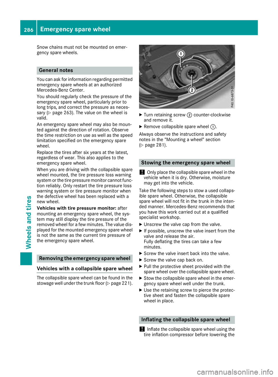
XTurn retaining screw ;counter-clockwise
and remove it.
XRemove collapsibl espare wheel :.
Alway sobserve the instructions and safety
notes in the "Mounting awheel"s ection
(
Ypage 281).
Stowin gthe emergencys pare wheel
!
Only place the collapsibl espare wheel in the
vehicl ewhenitisd ry.O therwise, moisture
may get into the vehicle.
Take the following stepstos towausedc ollaps-
ible spare wheel .Otherwise, the collapsible
spare wheel will not fit in the trunk in the inten-
ded manner. Mercedes-Benz recommendst hat
yo uh avet his work carrie doutataq uali fied
specialist workshop.
XUnscrewt he valve cap from the valve.
XIf possible ,unscrew the valve insert from the
valve and release the air.
Fully deflating the tire scan take afew
minutes.
XScrew the valve insert back into the valve.
XScrew the valve cap back on.
XPull the protectiv esheet provided with the
spare wheel overt he collapsiblespare wheel.
XStow the collapsibl espare wheel in the emer-
gency spare wheel well under the trunk.
XUse the retaining screwtop ierce the protec-
tive sheet and fasten the collapsibl espare
wheel in place.
Inflating the collapsibles pare wheel
!
Inflate the collapsibl espare wheel using the
tire inflation compressor before lowering the
286Emergencys pare wheel
Wheels and tires
Page 289 of 298
vehicle. The wheelrim could otherwise be
damaged.
!Do not operate the tire inflation compressor
for longer than eightm inutes atatime without
ab reak. It may otherwise overheat.
The tire inflation compressorc an be operated
again once it has cooled down.
XMount the collapsible spare wheelasd escri-
bed (Ypag e281).
The collapsible spare wheelm ust be mounted
before it is inflated.
XRemove the tire inflation compressorf rom
the stowage space under the trunk floor
(
Ypag e245).
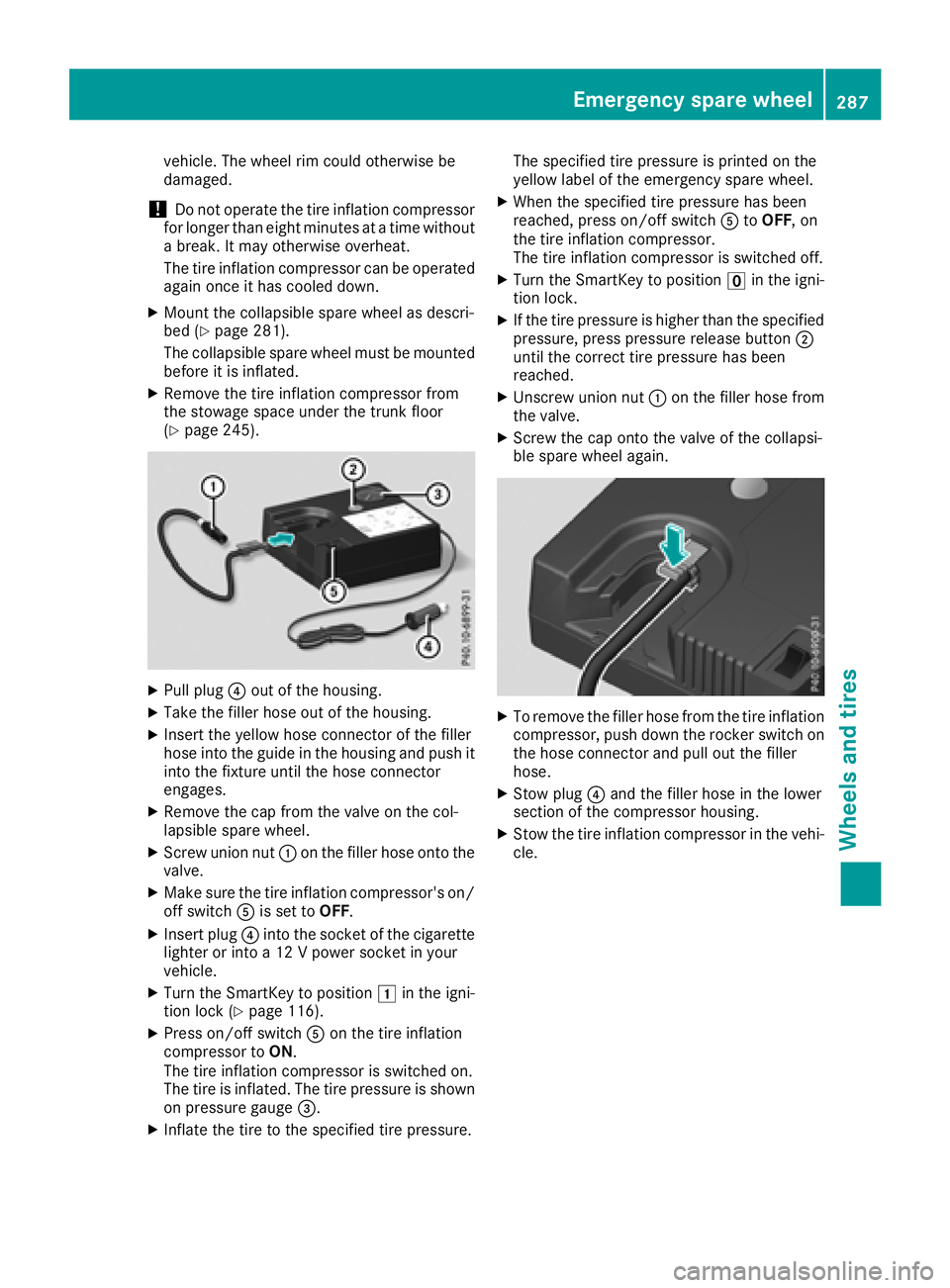
XPullplug ?out of the housing.
XTake the filler hose out of the housing.
XInsert the yellow hose connector of the filler
hose into the guide in the housing and push it
into the fixture until the hose connector
engages.
XRemove the cap from the valve on the col-
lapsibles pare wheel.
XScrew union nut :on the filler hose onto the
valve.
XMake sure the tire inflation compressor's on/
off switch Ais set to OFF.
XInsert plug ?into the socket of the cigarette
lighter or into a12Vpowers ocket in your
vehicle.
XTurn the SmartKey to position 1in the igni-
tion lock (Ypag e116).
XPress on/off switch Aon the tire inflation
compressort oON.
The tire inflation compressoriss witched on.
The tire is inflated. The tire pressure is shown
on pressure gauge =.
XInflate the tire to the specified tire pressure. The specified tire pressure is printed on the
yellow label of the emergency spare wheel.
XWhen the specified tire pressure has been
reached, press on/off switch
AtoOFF,o n
the tire inflation compressor.
The tire inflation compressoriss witched off.
XTurn the SmartKey to positionuin the igni-
tion lock.
XIf the tire pressure is highert han the specified
pressure, press pressure release button ;
until the correct tire pressure has been
reached.
XUnscrew union nut :on the filler hose from
the valve.
XScrew the cap onto the valve of the collapsi-
ble spare wheela gain.
XTo remove the filler hose from the tire inflation
compressor, push down the rocker switch on
the hose connector and pul lout the filler
hose.
XStow plug ?and the filler hose in the lower
section of the compressorh ousing.
XStow the tire inflation compressorint he vehi-
cle.
Emergency spare wheel287
Wheels and tires
Z