2018 MERCEDES-BENZ GLS SUV ECU
[x] Cancel search: ECUPage 305 of 398
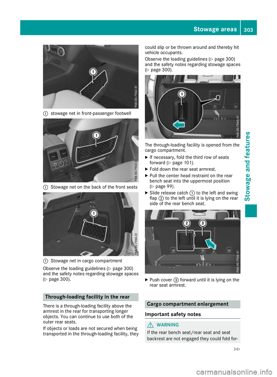
:stowage net in front-passenger footwell
:Stowage net on the back of the front seats
:Stowage net in cargo compartment
Observe the loading guidelines (
Ypage 300)
and the safety notes regarding stowage spaces
(
Ypage 300).
Through-loading facility in the rear
There is a through-loading facility above the
armrest in the rear for transporting longer
objects. You can continue to use both of the
outer rear seats.
If objects or loads are not secured when being
transported in the through-loading facility, they could slip or be thrown around and thereby hit
vehicle occupants.
Observe the loading guidelines (
Ypage 300)
and the safety notes regarding stowage spaces
(
Ypage 300).
The through-loading facility is opened from the
cargo compartment.
XIf necessary, fold the third row of seats
forward (Ypage 101).
XFold down the rear seat armrest.
XPull the center head restraint on the rear
bench seat into the uppermost position
(
Ypage 99).
XSlide release catch :to the left and swing
flap ;to the left until it is lying on the rear
side of the rear bench seat.
XPush cover =forward until it is lying on the
rear seat armrest.
Cargo compartment enlargement
Important safety notes
GWARNING
If the rear bench seat/rear seat and seat
backrest are not engaged they could fold for-
Stowage areas303
Stowage and features
Z
Page 307 of 398
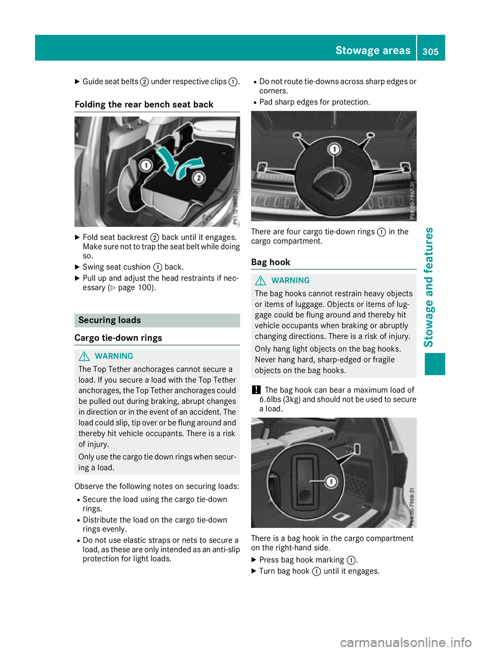
XGuide seat belts;under respective clips :.
Folding the rear bench seat back
XFold seat backrest;back until it engages.
Make sure not to trap the seat belt while doing so.
XSwing seat cushion :back.
XPull up and adjust the head restraints if nec-
essary (Ypage 100).
Securing loads
Cargo tie-down rings
GWARNING
The Top Tether anchorages cannot secure a
load. If you secure a load with the Top Tether
anchorages, the Top Tether anchorages could
be pulled out during braking, abrupt changes
in direction or in the event of an accident. The
load could slip, tip over or be flung around and
thereby hit vehicle occupants. There is a risk
of injury.
Only use the cargo tie down rings when secur-
ing a load.
Observe the following notes on securing loads:
RSecure the load using the cargo tie-down
rings.
RDistribute the load on the cargo tie-down
rings evenly.
RDo not use elastic straps or nets to secure a
load, as these are only intended as an anti-slip protection for light loads.
RDo not route tie-downs across sharp edges orcorners.
RPad sharp edges for protection.
There are four cargo tie-down rings :in the
cargo compartment.
Bag hook
GWARNING
The bag hooks cannot restrain heavy objects
or items of luggage. Objects or items of lug-
gage could be flung around and thereby hit
vehicle occupants when braking or abruptly
changing directions. There is a risk of injury.
Only hang light objects on the bag hooks.
Never hang hard, sharp-edged or fragile
objects on the bag hooks.
!The bag hook can bear a maximum load of
6.6lbs (3kg) and should not be used to secure
a load.
There is a bag hook in the cargo compartment
on the right-hand side.
XPress bag hook marking :.
XTurn bag hook:until it engages.
Stowage areas305
Stowage and features
Z
Page 308 of 398
Cargo compartment cover
Important safety notes
GWARNING
On its own, the cargo compartment cover
cannot secure or restrain heavy objects,
items of luggage and heavy loads. You could
be hit by an unsecured load during sudden
changes in direction, braking or in the event of
an accident. There is an increased risk of
injury or even fatal injury.
Always store objects so that they cannot be
flung around. Secure objects, luggage or
loads against slipping or tipping over, e.g. by
using tie downs, even if you are using the
cargo compartment cover.
!When loading the vehicle, make sure that
you do not stack the load in the cargo com-
partment higher than the lower edge of the
side windows. Do not place heavy objects on
top of the cargo compartment cover.
The cargo compartment cover may be installed
behind the 2nd or 3rd row of seats.
Extending/retracting the cargo com-
partment cover
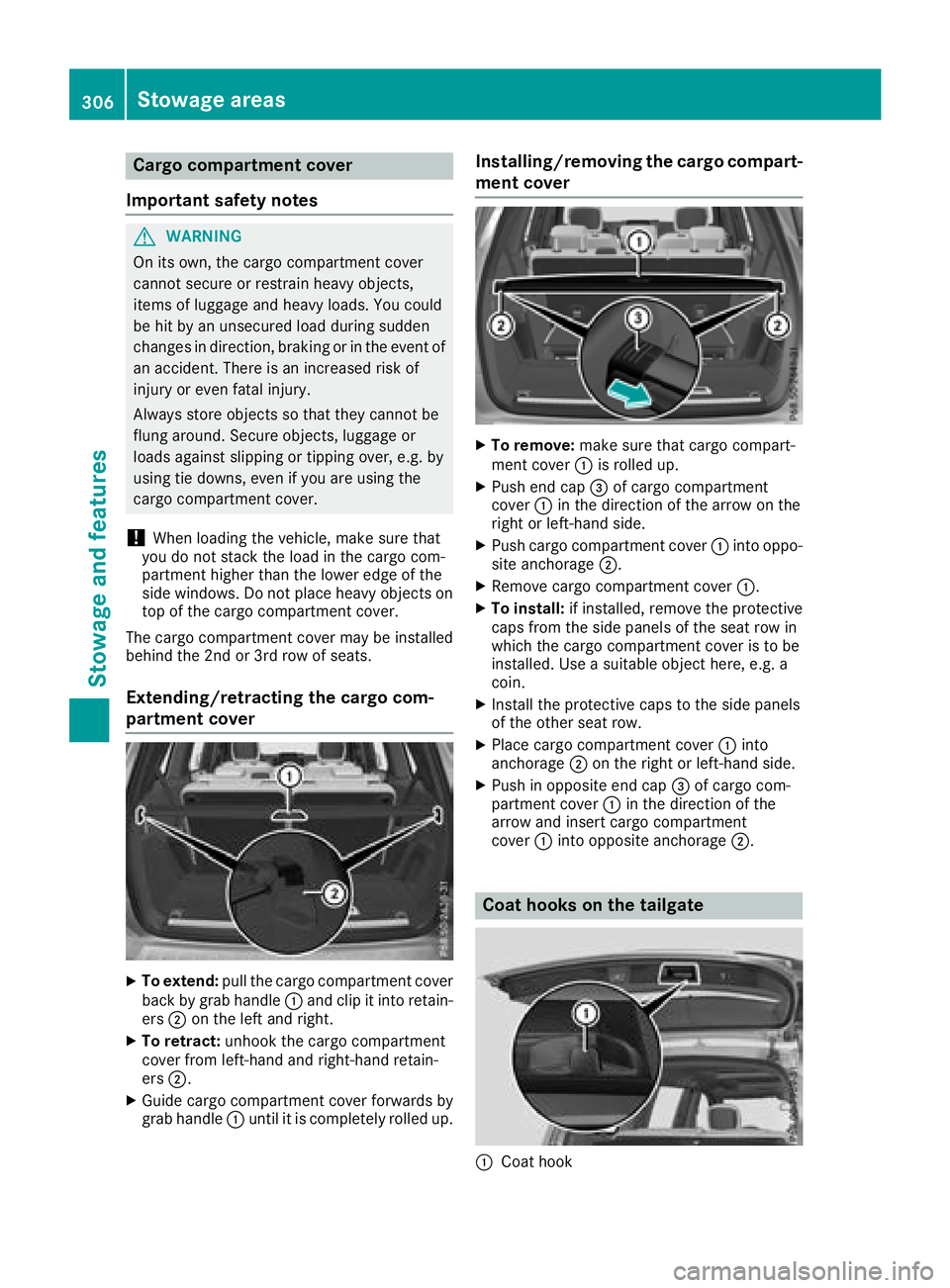
XTo extend: pull the cargo compartment cover
back by grab handle :and clip it into retain-
ers ;on the left and right.
XTo retract: unhook the cargo compartment
cover from left-hand and right-hand retain-
ers ;.
XGuide cargo compartment cover forwards by
grab handle :until it is completely rolled up.
Installing/removing the cargo compart-
ment cover
XTo remove: make sure that cargo compart-
ment cover :is rolled up.
XPush end cap =of cargo compartment
cover :in the direction of the arrow on the
right or left-hand side.
XPush cargo compartment cover :into oppo-
site anchorage ;.
XRemove cargo compartment cover :.
XTo install:if installed, remove the protective
caps from the side panels of the seat row in
which the cargo compartment cover is to be
installed. Use a suitable object here, e.g. a
coin.
XInstall the protective caps to the side panels
of the other seat row.
XPlace cargo compartment cover :into
anchorage ;on the right or left-hand side.
XPush in opposite end cap =of cargo com-
partment cover :in the direction of the
arrow and insert cargo compartment
cover :into opposite anchorage ;.
Coat hooks on the tailgate
:Coat hook
306Stowage areas
Stowage and features
Page 310 of 398
Roof carrier
Important safety notes
GWARNING
When you load the roof, the center of gravity
of the vehicle rises and the driving character-
istics change. If you exceed the maximum roof
load, the driving characteristics, as well as
steering and braking, will be greatly impaired.
There is a risk of an accident.
Never exceed the maximum roof load and
adjust your driving style.
!Mercedes-Benz recommends that you only
use roof carriers that have been tested and
approved for Mercedes-Benz vehicles. This
helps to prevent damage to the vehicle.
Position the load on the roof carrier in such a
way that the vehicle will not sustain damage
even when it is in motion.
Depending on the vehicle equipment, ensure
that when the roof carrier is installed you can:
Rraise the sliding sunroof fully
Ropen the panorama roof with power tilt/
sliding panel fully
Ropen the tailgate fully
You will find information on the maximum roof
load in the "Technical data" section
(
Ypage 392).
An incorrectly secured roof carrier or roof load
may become detached from the vehicle. You
must therefore ensure that you observe the roof
carrier manufacturer's installation instructions.
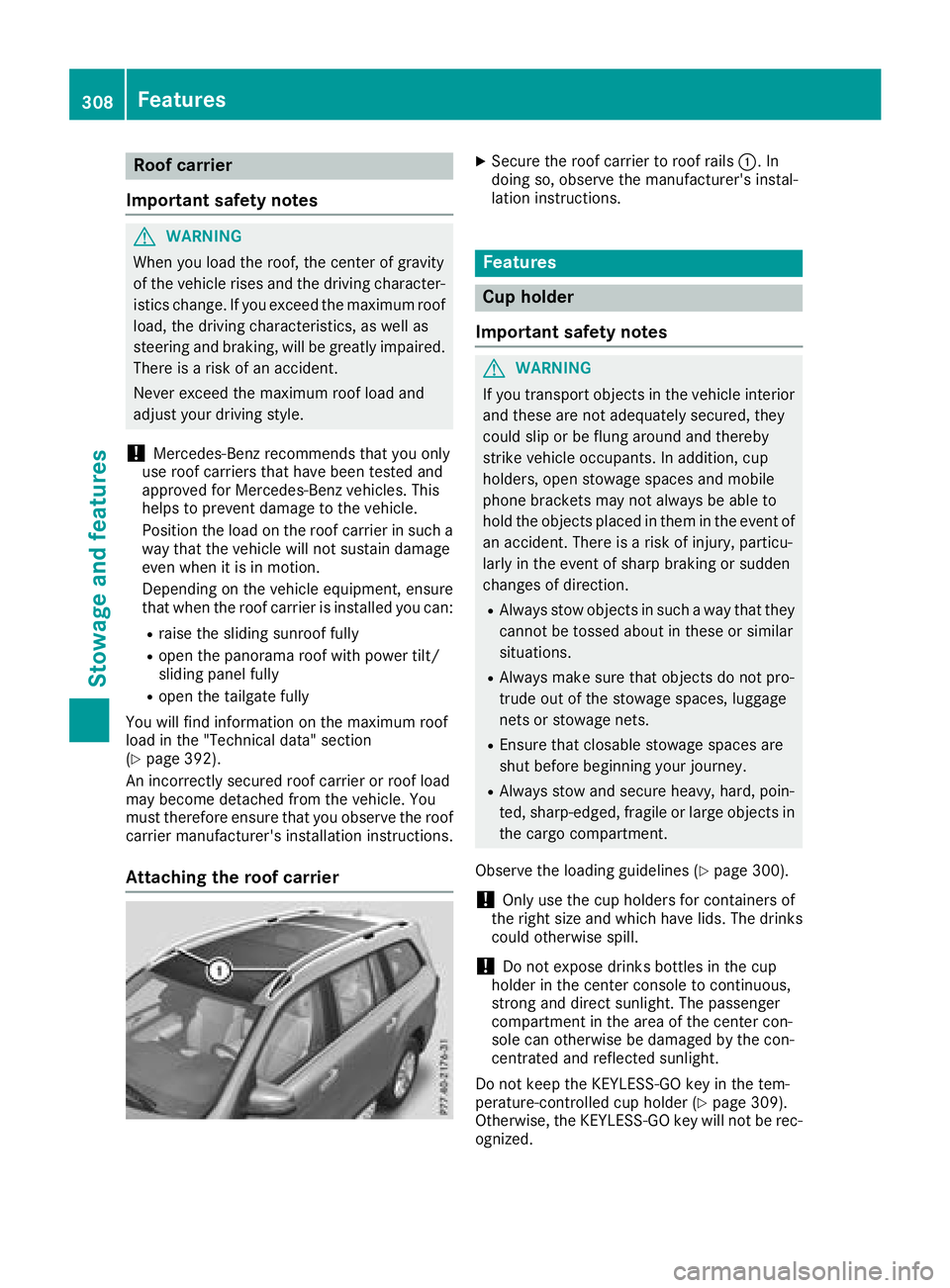
Attaching the roof carrier
XSecure the roof carrier to roof rails :. In
doing so, observe the manufacturer's instal-
lation instructions.
Features
Cup holder
Important safety notes
GWARNING
If you transport objects in the vehicle interior
and these are not adequately secured, they
could slip or be flung around and thereby
strike vehicle occupants. In addition, cup
holders, open stowage spaces and mobile
phone brackets may not always be able to
hold the objects placed in them in the event of
an accident. There is a risk of injury, particu-
larly in the event of sharp braking or sudden
changes of direction.
RAlways stow objects in such a way that they cannot be tossed about in these or similar
situations.
RAlways make sure that objects do not pro-
trude out of the stowage spaces, luggage
nets or stowage nets.
REnsure that closable stowage spaces are
shut before beginning your journey.
RAlways stow and secure heavy, hard, poin-
ted, sharp-edged, fragile or large objects in
the cargo compartment.
Observe the loading guidelines (
Ypage 300).
!Only use the cup holders for containers of
the right size and which have lids. The drinks
could otherwise spill.
!Do not expose drinks bottles in the cup
holder in the center console to continuous,
strong and direct sunlight. The passenger
compartment in the area of the center con-
sole can otherwise be damaged by the con-
centrated and reflected sunlight.
Do not keep the KEYLESS-GO key in the tem-
perature-controlled cup hol der (
Ypage 309).
Otherwise, the KEYLESS-GO key will not be rec-
ognized.
308Features
Stowage and features
Page 311 of 398
The stowage compartments in the doors provide
space for bottles with a capacity of up to
34 fl. oz. (1.0l).
The bottles are not secured or prevented from
tipping over. Therefore, do not place any open
drink containers in the stowage compartments.
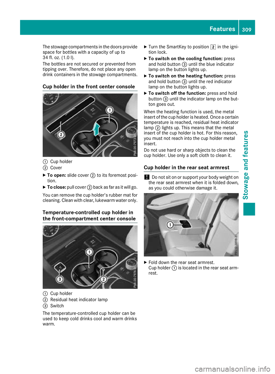
Cup holder in the front center console
:Cup holder
;Cover
XTo open: slide cover ;to its foremost posi-
tion.
XTo close: pull cover ;back as far as it will go.
You can remove the cup holder's rubber mat for
cleaning. Clean with clear, lukewarm water only.
Temperature-controlled cup holder in
the front-compartment center console
:Cup holder
;Residual heat indicator lamp
=Switch
The temperature-controlled cup holder can be
used to keep cold drinks cool and warm drinks
warm.
XTurn the SmartKey to position 2in the igni-
tion lock.
XTo switch on the cooling function: press
and hold button =until the blue indicator
lamp on the button lights up.
XTo switch on the heating function: press
and hold button =until the red indicator
lamp on the button lights up.
XTo switch off the function: press and hold
button =until the indicator lamp on the but-
ton goes out.
When the heating function is used, the metal
insert of the cup holder is heated. Once a certain
temperature is reached, residual heat indicator
lamp ;lights up. This means that the metal
insert of the cup holder is hot. For this reason,
you must not reach into the cup holder metal
insert.
Do not use hard or sharp objects to clean the
cup holder. Use only a soft cloth to clean it.
Cup holder in the rear seat armrest
!Do not sit on or support your body weight on
the rear seat armrest when it is folded down,
as you could otherwise damage it.
XFold down the rear seat armrest.
Cup holder :is located in the rear seat arm-
rest.
Features309
Stowage and features
Z
Page 317 of 398

The system offers various services, e.g.:
RAutomatic and manual emergency call
RRoadside Assistance call
RInfo call
You can find information and a description of all
available features under "Owners Online" at
http://www.mbusa.com.
System self-test
After you have switched on the ignition, the sys- tem carries out a self-diagnosis.
A malfunction in the system has been detected
if one of the following occurs:
RThe indicator lamp in the SOS button does not
come on during the system self-test.
RThe indicator lamp in the FRoadside
Assistance button does not light up during
self-diagnosis of the system.
RThe indicator lamp in the ïInfo call button
does not light up during the system self-diag-
nosis.
RThe indicator lamp in one or more of the fol-
lowing buttons continues to light up red after
the system self-diagnosis:
-SOS button
-F Roadside Assistance call button
-ïInfo call button
RTheInoperativeor the Service NotActivatedmessage appears in the multi-
function display after the system self-diagno-
sis.
If a malfunction is indicated as outlined above,
the system may not operate as expected. In the
event of an emergency, help will have to be
summoned by other means.
Have the system checked at the nearest author-
ized Mercedes-Benz Center or call the following
telephone assistance services:
Mercedes-Benz Customer Assistance Center at
1-800 FOR-MERCEDES (1-800-367-6372) or
1-866-990-9007.
Emergency call
Important safety notes
GWARNING
It can be dangerous to remain in the vehicle,
even if you have pressed the SOS button in an emergency if:
Ryou see smoke inside or outside of the vehi-
cle, e.g. if there is a fire after an accident
Rthe vehicle is on a dangerous section of
road
Rthe vehicle is not visible or cannot easily beseen by other road users, particularly when
dark or in poor visibility conditions
There is a risk of an accident and injury.
Leave the vehicle immediately in this or simi-
lar situations as soon as it is safe to do so.
Move to a safe location along with other vehi-
cle occupants. In such situations, secure the
vehicle in accordance with national regula-
tions, e. g. with a warning triangle.
General notes
Observe the notes on system activation
(Ypage 314).
The emergency call is triggered automatically if
an air bag is deployed or an Emergency Ten-
sioning Device is triggered. You cannot end an
automatically triggered emergency call yourself.
An emergency call can also be initiated man-
ually.
As soon as the emergency call has been initi-
ated, the indicator lamp in the SOS button
flashes. The Connecting Call
message
appears in the multifunction display.
The audio output is muted.
Once the connection has been made, the Call
Connectedmessage appears in the multifunc-
tion display.
All important information on the emergency is
transmitted, for example:
RCurrent location of the vehicle (as determined
by the GPS system)
RVehicle identification number
RInformation on the severity of the accident
Shortly after the emergency call has been initi-
ated, a voice connection is automatically estab-
Features315
Stowage and features
Z
Page 326 of 398
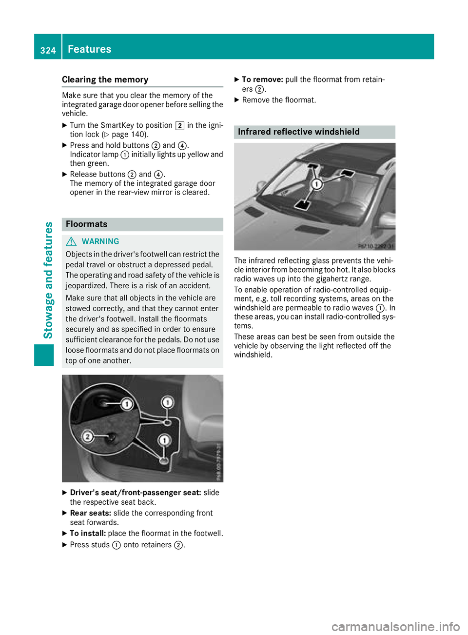
Clearing the memory
Make sure that you clear the memory of the
integrated garage door opener before selling the
vehicle.
XTurn the SmartKey to position2in the igni-
tion lock (Ypage 140).
XPress and hold buttons ;and ?.
Indicator lamp :initially lights up yellow and
then green.
XRelease buttons ;and ?.
The memory of the integrated garage door
opener in the rear-view mirror is cleared.
Floormats
GWARNING
Objects in the driver's footwell can restrict the pedal travel or obstruct a depressed pedal.
The operating and road safety of the vehicle is
jeopardized. There is a risk of an accident.
Make sure that all objects in the vehicle are
stowed correctly, and that they cannot enter
the driver's footwell. Install the floormats
securely and as specified in order to ensure
sufficient clearance for the pedals. Do not use
loose floormats and do not place floormats on
top of one another.
XDriver's seat/front-passenger seat: slide
the respective seat back.
XRear seats: slide the corresponding front
seat forwards.
XTo install: place the floormat in the footwell.
XPress studs :onto retainers ;.
XTo remove:pull the floormat from retain-
ers ;.
XRemove the floormat.
Infrared reflective windshield
The infrared reflecting glass prevents the vehi-
cle interior from becoming too hot. It also blocks
radio waves up into the gigahertz range.
To enable operation of radio-controlled equip-
ment, e.g. toll recording systems, areas on the
windshield are permeable to radio waves :. In
these areas, you can install radio-controlled sys-
tems.
These areas can best be seen from outside the
vehicle by observing the light reflected off the
windshield.
324Features
Stowage and features
Page 329 of 398
When checking the oil level:
Rpark the vehicle on a level surface.
Rthe engine should be switched off for approx-
imately five minutes if the engine is at normal
operating temperature.
Rif the engine is not at normal operating tem-
perature, e.g. if the engine was only started
briefly, wait about 30 minutes before carrying
out the measurement.
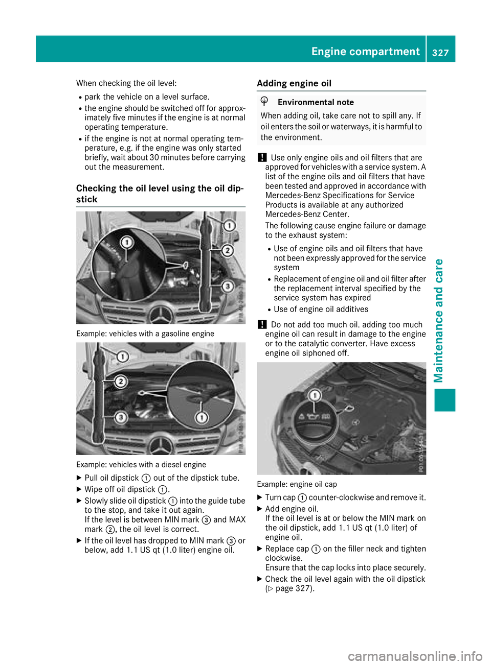
Checking the oil level using the oil dip-
stick
Example: vehicles with a gasoline engine
Example: vehicles with a diesel engine
XPull oil dipstick :out of the dipstick tube.
XWipe off oil dipstick :.
XSlowly slide oil dipstick :into the guide tube
to the stop, and take it out again.
If the level is between MIN mark =and MAX
mark ;, the oil level is correct.
XIf the oil level has dropped to MIN mark =or
below, add 1.1 US qt (1.0 liter) engine oil.
Adding engine oil
HEnvironmental note
When adding oil, take care not to spill any. If
oil enters the soil or waterways, it is harmful to
the environment.
!Use only engine oils and oil filters that are
approved for vehicles with a service system. A list of the engine oils and oil filters that have
been tested and approved in accordance with
Mercedes-Benz Specifications for Service
Products is available at any authorized
Mercedes-Benz Center.
The following cause engine failure or damage
to the exhaust system:
RUse of engine oils and oil filters that have
not been expressly approved for the service
system
RReplacement of engine oil and oil filter after
the replacement interval specified by the
service system has expired
RUse of engine oil additives
!Do not add too much oil. adding too much
engine oil can result in damage to the engine
or to the catalytic converter. Have excess
engine oil siphoned off.
Example: engine oil cap
XTurn cap :counter-clockwise and remove it.
XAdd engine oil.
If the oil level is at or below the MIN mark on
the oil dipstick, add 1.1 US qt (1.0 liter) of
engine oil.
XReplace cap :on the filler neck and tighten
clockwise.
Ensure that the cap locks into place securely.
XCheck the oil level again with the oil dipstick
(Ypage 327).
Engine compartment327
Maintenance and care
Z