2018 MERCEDES-BENZ G-CLASS length
[x] Cancel search: lengthPage 158 of 294

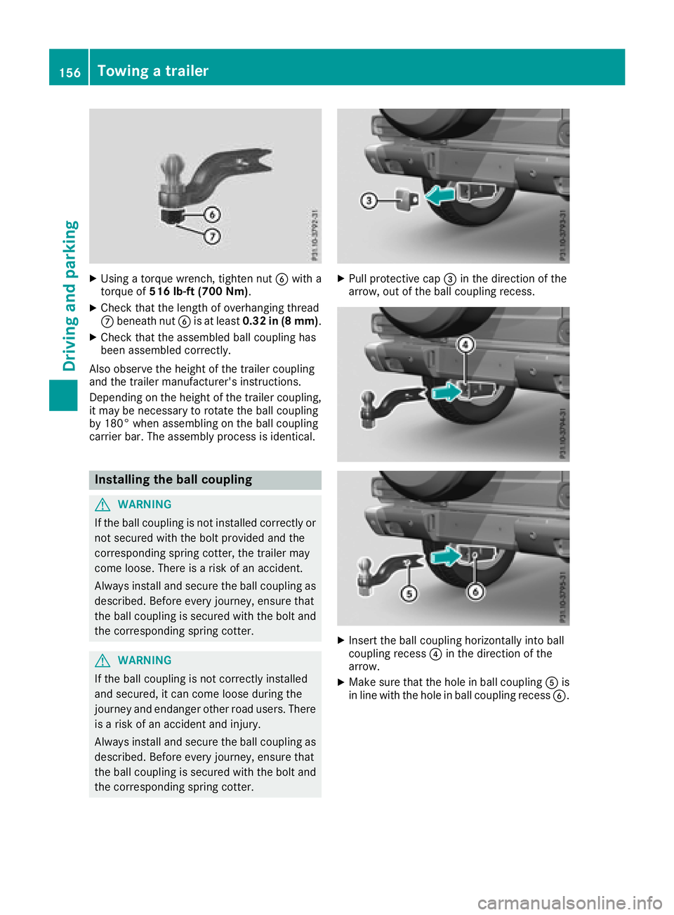
XUsing a torque wrench, tighten nutBwith a
torque of 516 lb-ft (700 Nm) .
XCheck that the length of overhanging thread
Cbeneath nut Bis at least 0.32 in (8 mm) .
XCheck that the assembled ball coupling has
been assembled correctly.
Also observe the height of the trailer coupling
and the trailer manufacturer's instructions.
Depending on the height of the trailer coupling,
it may be necessary to rotate the ball coupling
by 180° when assembling on the ball coupling
carrier bar. The assembly process is identical.
Installing the ball coupling
GWARNING
If the ball coupling is not installed correctly or not secured with the bolt provided and the
corresponding spring cotter, the trailer may
come loose. There is a risk of an accident.
Always install and secure the ball coupling as
described. Before every journey, ensure that
the ball coupling is secured with the bolt and
the corresponding spring cotter.
GWARNING
If the ball coupling is not correctly installed
and secured, it can come loose during the
journey and endanger other road users. There is a risk of an accident and injury.
Always install and secure the ball coupling as
described. Before every journey, ensure that
the ball coupling is secured with the bolt and
the corresponding spring cotter.
XPull protective cap =in the direction of the
arrow, out of the ball coupling recess.
XInsert the ball coupling horizontally into ball
coupling recess ?in the direction of the
arrow.
XMake sure that the hole in ball coupling Ais
in line with the hole in ball coupling recess B.
156Towing a trailer
Driving and parking
Page 159 of 294

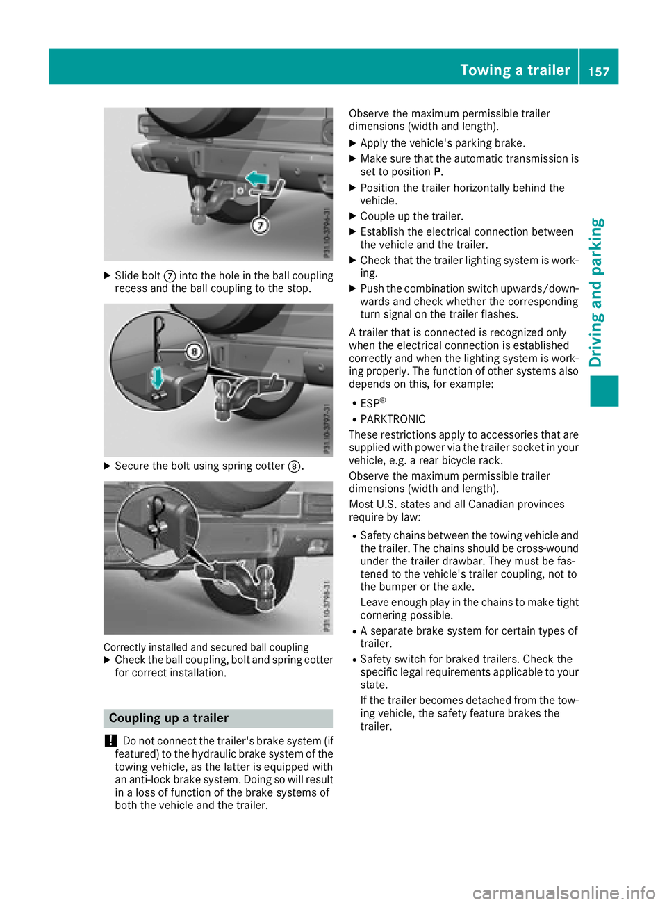
XSlide boltCinto the hole in the ball coupling
recess and the ball coupling to the stop.
XSecure the bolt using spring cotter D.
Correctly installed and secured ball couplingXCheck the ball coupling, bolt and spring cotter
for correct installation.
Coupling up a trailer
!
Do not connect the trailer's brake system (if
featured) to the hydraulic brake system of the
towing vehicle, as the latter is equipped with
an anti-lock brake system. Doing so will result
in a loss of function of the brake systems of
both the vehicle and the trailer. Observe the maximum permissible trailer
dimensions (width and length).
XApply the vehicle's parking brake.
XMake sure that the automatic transmission is
set to position
P.
XPosition the trailer horizontally behind the
vehicle.
XCouple up the trailer.
XEstablish the electrical connection between
the vehicle and the trailer.
XCheck that the trailer lighting system is work-
ing.
XPush the combination switch upwards/down-
wards and check whether the corresponding
turn signal on the trailer flashes.
A trailer that is connected is recognized only
when the electrical connection is established
correctly and when the lighting system is work-
ing properly. The function of other systems also
depends on this, for example:
RESP®
RPARKTRONIC
These restrictions apply to accessories that are
supplied with power via the trailer socket in your
vehicle, e.g. a rear bicycle rack.
Observe the maximum permissible trailer
dimensions (width and length).
Most U.S. states and all Canadian provinces
require by law
:
RSafety chains between the towing vehicle and
the trailer. The chains should be cross-wound
under the trailer drawbar. They must be fas-
tened to the vehicle's trailer coupling, not to
the bumper or the axle.
Leave enough play in the chains to make tight
cornering possible.
RA separate brake system for certain types of
trailer.
RSafety switch for braked trailers. Check the
specific legal requirements applicable to your
state.
If the trailer becomes detached from the tow-
ing vehicle, the safety feature brakes the
trailer.
Towing a trailer157
Driving and parking
Z
Page 160 of 294

Towing a trailer
There are several legal requirements for towing
a trailer, e.g. the maximum permissible speed.
Make sure that your car/trailer combination
complies with the local regulations:
Rin your place of residence
Rat your destination
The police and local authorities can provide reli- able information.
In order to accumulate driving experience and
accustom yourself to the new handling charac-
teristics, practice the following at a location
where there is no traffic:
RCornering
RStopping
RBacking up
Before driving, check the following:
RTrailer tow hitch
RSafety switch for braked trailers
RSafety chains
RElectrical connections
RLighting system
RWheels and tires
RLoad-securing measures
Adjust the exterior mirrors to provide an unob-
structed view of the rear section of the trailer.
Trailers with electronically controlled
brakes: pull away carefully in the vehicle/trailer
combination, brake manually using the brake
controller and check whether the brakes func-
tion correctly.
Check the load securing measures on a regular
basis.
When towing a trailer, your vehicle's handling
characteristics will be different in comparison
with when driving without a tra
iler.
The vehicle/trailer combination:
Ris heavier
Ris restricted in its acceleration and gradient-
climbing capability
Rhas an increased braking distance
Ris affected more by strong crosswinds
Rdemands more sensitive steering
Rhas a larger turning radius
Avoid sudden steering movements.
Avoid braking abruptly. If possible, brake gently
at first to allow the trailer to run on. Then,
increase the braking force rapidly. When overtaking, pay particular attention to the
extended length of your vehicle/trailer combi-
nation.
Due to the length of the vehicle/trailer combi-
nation, you require additional road space when
overtaking before you can change back to the
original lane.
If the automatic transmission repeatedly shifts
between gears on uphill or downhill gradients,
shift to a lower gear.
Driving in a lower gear and at a reduced speed
decreases the risk of engine damage.
Avoid constant braking. Otherwise, the vehicle
brakes and possibly also the trailer brakes may
overheat.
When driving downhill, shift to a lower gear to
utilize the engine's braking effect.
If the coolant temperature increases dramati-
cally while the air-conditioni ng s
ystem is
switched on, switch off the air-conditioning sys- tem.
Coolant heat can also be dissipated by opening
the windows and switching the ventilation
blower and the interior temperature to the high-
est level.
Decoupling a trailer
GWARNING
If you uncouple a trailer with the overrun
brake engaged, you could trap your hand
between the vehicle and the trailer drawbar.
There is a risk of injury.
Do not uncouple a trailer if the overrun brake
is engaged.
!Do not disconnect a trailer with an engaged
overrun brake. Otherwise, your vehicle could
be damaged by the rebounding of the overrun
brake.
XApply the parking brake.
XMake sure that the automatic transmission is
set to position P.
XSecure the vehicle and trailer against rolling
away.
XClose all doors, including the rear door.
XRemove the trailer cable.
XRemove the safety chains, if there are any.
XUncouple the trailer.
158Towing a trailer
Driving an d parking
Page 175 of 294

If you switch off the engine, the RACE TIMER is
reset to "0" after 30 seconds. All laps are
deleted.
You cannot delete individual stored laps. If you
have stopped 16 laps, the current lap does not
have to be reset.
XReset the current lap (Ypage 172).
XPressato confirm Reset.
The Reset Race-Timer?display message
appears in the multifunction display.
XPress the :button to select Yesand press
the a button to confirm.
All laps are deleted.
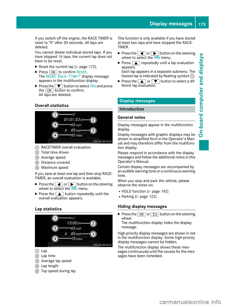
Overall statistics
:RACETIMER overall evaluation
;Total time driven
=Average speed
?Distance covered
AMaximum speed
If you save at least one lap and then stop RACE- TIMER, an overall evaluation is available.
XPress the =or; button on the steering
wheel to select the AMGmenu.
XPress the9button repeatedly until the
overall evaluation appears.
Lap statistics
:Lap
;Lap time
=Average lap speed
?Lap length
ATop speed during lap This function is only available if you have stored
at least two laps and have stopped the RACE-
TIMER.
XPress the
=or; button on the steering
wheel to select the AMGmenu.
XPress9repeatedly until a lap evaluation
appears.
Each lap appears in a separate submenu. The
fastest lap is indicated by flashing symbol :.
XPress the9or: button to select a dif-
ferent lap evaluation.
Display messages
Introduction
General notes
Display messages appear in the multifunction
display.
Display messages with graphic displays may be
shown in simplified form in the Operator's Man-
ual and may therefore differ from the multifunc-
tion display.
Please respond in accordance with the display
messages and follow the additional notes in this
Operator's Manual.
Certain display messages are accompanied by
an audible warning tone or a continuous warning
tone.
When you stop and park the vehicle, please
observe the notes on:
RHOLD function (Ypage 142)
RParking (Ypage 122)
Hiding display messages
XPress the aor% button on the steering
wheel.
The multifunction display hides the display
message.
High-priority display messages are shown in red
in the multifunction display. Some high-priority
display messages cannot be hidden.
The multifunction display shows these mes-
sages continuously until the causes for the mes-
sages have been remedied.
Display messages173
On-board computer and displays
Z
Page 250 of 294

In order for the battery to achieve the maximum
possible service life, it must always be suffi-
ciently charged.
Like other batteries, the vehicle battery may
discharge over time if you do not use the vehicle.
In this case, have the battery disconnected at a
qualified specialist workshop. You can also
charge the battery with a charger recommended
by Mercedes-Benz. Contact a qualified special-
ist workshop for further information.
Have the battery condition of charge checked
more frequently if you use the vehicle mainly for
short trips or if you leave it standing idle for a
lengthy period. Consult a qualified specialist
workshop if you wish to leave your vehicle
parked for a long period of time.
Remove the SmartKey if you park the vehicle
and do not require any electrical consumers.
The vehicle will then use very little energy, thus
conserving battery power.
iIf the power supply has been interrupted,
e.g. due to a discharged battery, you will have
to:
Rreset the head restraints on the front seats (Ypage 76)
Rreset the function for automatically folding
the exterior mirrors in/out by folding the
mirrors out once (
Ypage 82)
Charging the battery
!
Only use battery chargers with a maximum
charging voltage of 14.8 V.
GWARNING
During charging and jump-starting, explosive
gases can escape from the battery. There is a risk of an explosion.
Particularly avoid fire, open flames, creating
sparks and smoking. Ensure there is sufficient
ventilation while charging and jump-starting.
Do not lean over a battery.
GWARNING
Battery acid is caustic. There is a risk of injury.
Avoid contact with skin, eyes or clothing. Do
not inhale any battery gases. Do not lean over
the battery. Keep children away from batter-
ies. Wash away battery acid immediately with plenty of clean water and seek medical atten-
tion.
GWARNING
A discharged battery can freeze at tempera-
tures below freezing point. When jump-start-
ing the vehicle or charging the battery, gases can escape from the battery. There is a risk of
an explosion.
Allow the frozen battery to thaw out before
charging it or jump-starting.
!Only charge the battery using the jump-
starting connection point.
The jump-starting connection point is in the
engine compartment (
Ypage 249).
XOpen the hood.
XConnect the battery charger to the positive
terminal and ground point in the same order
as when connecting the donor battery in the
jump-starting procedure (
Ypage 249).
Keep away from fire and open flames. Do not
lean over a battery. Never charge the battery if it
is still installed in the vehicle, unless you use a
battery charger which has been tested and
approved by Mercedes-Benz. A battery charger
unit specially adapted for Mercedes-Benz vehi-
cles and tested and approved by Mercedes-
Benz is available as an accessory. It permits the
charging of the battery in its installed position.
Contact an authorized Mercedes-Benz Center
for further information and availability. Read the
battery charger's operating instructions before
charging the battery.
If the warning and indicator lamps do not light up
on the instrument cluster when temperatures
are low, it is probably because the discharged
battery has frozen. In this case you may neither
jump-start the vehicle nor charge the battery.
The service life of a thawed-out battery may be
shorter. The starting characteristics can be
impaired, particularly at low temperatures. Have
the thawed-out battery checked at a qualified
specialist workshop.
248Battery (vehicle)
Breakdown assistance
Page 251 of 294

Jump starting
For the jump-starting procedure, use only the jump-starting connection point in the engine com-
partment, consisting of a positive terminal and a ground point.
GWARNING
Battery acid is caustic. There is a risk of injury.
Avoid contact with skin, eyes or clothing. Do not inhale any battery gases. Do not lean over the
battery. Keep children away from batteries. Wash away battery acid immediately with plenty of
clean water and seek medical attention.
GWARNING
During charging and jump-starting, explosive gases can escape from the battery. There is a risk of an explosion.
Particularly avoid fire, open flames, creating sparks and smoking. Ensure there is sufficient ven-
tilation while charging and jump-starting. Do not lean over a battery.
GWARNING
During the charging process, a battery produces hydrogen gas. If a short circuit occurs or sparks
are created, the hydrogen gas can ignite. There is a risk of an explosion.
RMake sure that the positive terminal of a connected battery does not come into contact with
vehicle parts.
RNever place metal objects or tools on a battery.
RIt is important that you observe the described order of the battery terminals when connecting
and disconnecting a battery.
RWhen jump-starting, make sure that the battery poles with identical polarity are connected.
RIt is particularly important to observe the described order when connecting and disconnecting
the jumper cables.
RNever connect or disconnect the battery terminals while the engine is running.
GWARNING
A discharged battery can freeze at temperatures below freezing point. When jump-starting the
vehicle or charging the battery, gases can escape from the battery. There is a risk of an explosion. Allow the frozen battery to thaw out before charging it or jump-starting.
!Avoid repeated and lengthy starting attempts. Otherwise, the catalytic converter could be
damaged by the non-combusted fuel.
If the warning and indicator lamps do not light up on the instrument cluster when temperatures are
low, it is probably because the discharged battery has frozen. In this case, you may neither charge
the battery nor jump-start the vehicle. The service life of a thawed-out battery may be shorter. The
starting characteristics can be impaired, particularly at low temperatures. Have the thawed-out
battery checked at a qualified specialist workshop.
Jump starting249
Breakdown assistance
Z
Page 290 of 294

Refrigerant instruction label
Example: refrigerant instruction label
:Warning symbol
;Refrigerant filling capacity
=Applicable standards
?PAG oil part number
AType of refrigerant
Warning symbol :advises you about:
RPossible dangers
RHaving service work carried out at a qualified
specialist workshop
Filling capacities
Missing values were not available at time of
going to print.
ModelRefrigerant
Mercedes-AMG vehicles
G 550
ModelPAG oil
Mercedes-AMG vehicles
G 550
Vehicle data
General notes
Please note that for the specified vehicle data:
RThe heights specified may vary as a result of:
-Tires
-Load
-Condition of the suspension
-Optional equipment
RThe vehicle length specified includes the front
license plate adapter.
Dimensions and weights
Missing values were not available at time of
going to print.
G 550
: Distance to top
edge75 in - 78.9 in
(1905 mm -2005 mm)
; Distance to lower
edge26.8 in - 30.7 in
(680 mm -780 mm)
= Range of movement36.7 in (931 mm)
288Vehicle data
Technical data
Page 291 of 294

Mercedes-AMGG 63
:Upper-edge clear-
ance74.5 in - 78.4 in
(1892 mm -1992 mm)
; Lower-edge clear-
ance26.3 in - 30.2 in
(667 mm -767 mm)
= Range of movement36.7 in (931 mm)
Mercedes-AMG
G 65
:Distance to top
edge
; Distance to lower
edge
= Range of movement
Missing values were not available at time of
going to print.
G 550
Vehicle length187.6 in
(4764 mm)
Vehicle width including
exterior mirrors80.9 in
(2056 mm)
Vehicle height76.9 in
(1954 mm)
Wheelbase112.2 in
(2850 mm)
Minimum ground clear-
ance9.3 in
(235 mm)
Maximum roof load331 lb
(150 kg)
Turning radius44.6 ft
(13.60 m)
Gross vehicle weight rat-
ing (GVWR)7054.8 lb
(3200 kg)
Gross axle weight rating
(GAWR), front3417.1 lb
(1550 kg)
Gross axle weight rating
(GAWR), rear4188.7 lb
(1900 kg)
Mercedes-AMG G 63
Vehicle length187.8 in
(4769 mm)
Vehicle width including
exterior mirrors80.9 in
(2056 mm)
Vehicle height76.3 in
(1938 mm)
Wheelbase112.2 in
(2850 mm)
Minimum ground clear-
ance
Maximum roof load330 lb
(150 kg)
Turning radius44.6 ft
(13.60 m)
Gross vehicle weight rat-
ing (GVWR)7054.8 lb
(3200 kg)
Gross axle weight rating
(GAWR), front3417.1 lb
(1550 kg)
Gross axle weight rating
(GAWR), rear4122.6 lb
(1870 kg)
Mercedes-AMG G 65
Vehicle length187.8 in
(4769 mm)
Vehicle width including
exterior mirrors80.9 in
(2056 mm)
Vehicle height76.3 in
(1938 mm)
Wheelbase112.2 in
(2850 mm)
Minimum ground clear-
ance
Maximum roof load
Turning radius44.6 ft
(13.60 m)
Gross vehicle weight rat-
ing (GVWR)
Vehicle data289
Technical data
Z