Page 360 of 656
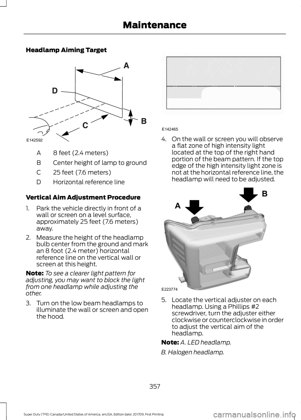
Headlamp Aiming Target
8 feet (2.4 meters)
A
Center height of lamp to ground
B
25 feet (7.6 meters)
C
Horizontal reference line
D
Vertical Aim Adjustment Procedure
1. Park the vehicle directly in front of a wall or screen on a level surface,
approximately 25 feet (7.6 meters)
away.
2. Measure the height of the headlamp bulb center from the ground and mark
an 8 foot (2.4 meter) horizontal
reference line on the vertical wall or
screen at this height.
Note: To see a clearer light pattern for
adjusting, you may want to block the light
from one headlamp while adjusting the
other.
3. Turn on the low beam headlamps to illuminate the wall or screen and open
the hood. 4. On the wall or screen you will observe
a flat zone of high intensity light
located at the top of the right hand
portion of the beam pattern. If the top
edge of the high intensity light zone is
not at the horizontal reference line, the
headlamp will need to be adjusted. 5. Locate the vertical adjuster on each
headlamp. Using a Phillips #2
screwdriver, turn the adjuster either
clockwise or counterclockwise in order
to adjust the vertical aim of the
headlamp.
Note: A. LED headlamp.
B. Halogen headlamp.
357
Super Duty (TFE) Canada/United States of America, enUSA, Edition date: 201709, First Printing MaintenanceE142592 E142465 A
B
E223774
Page 361 of 656
6. Repeat steps 3 thru 5 to adjust the
other headlamp.
7. Close the hood and turn off the lamps.
Horizontal Aim Adjustment
Horizontal aim is not required for this
vehicle and is not adjustable.
CHANGING A BULB WARNINGS
Switch the lamps and the ignition off.
Failure to follow this warning could
result in serious personal injury.
Bulbs become hot when in use. Let
them cool down before you remove
them.
Use the correct specification bulb. See
Bulb Specification Chart (page 361).
Install in the reverse order unless otherwise
stated.
Front Park and Direction Indicator
Lamp Bulbs
Note: To access the right-hand side bulbs,
remove the air intake pipe. See
Changing
the Engine Air Filter (page 363).
To access the left-hand side bulbs, remove
the washer reservoir filler tube. Vehicles with
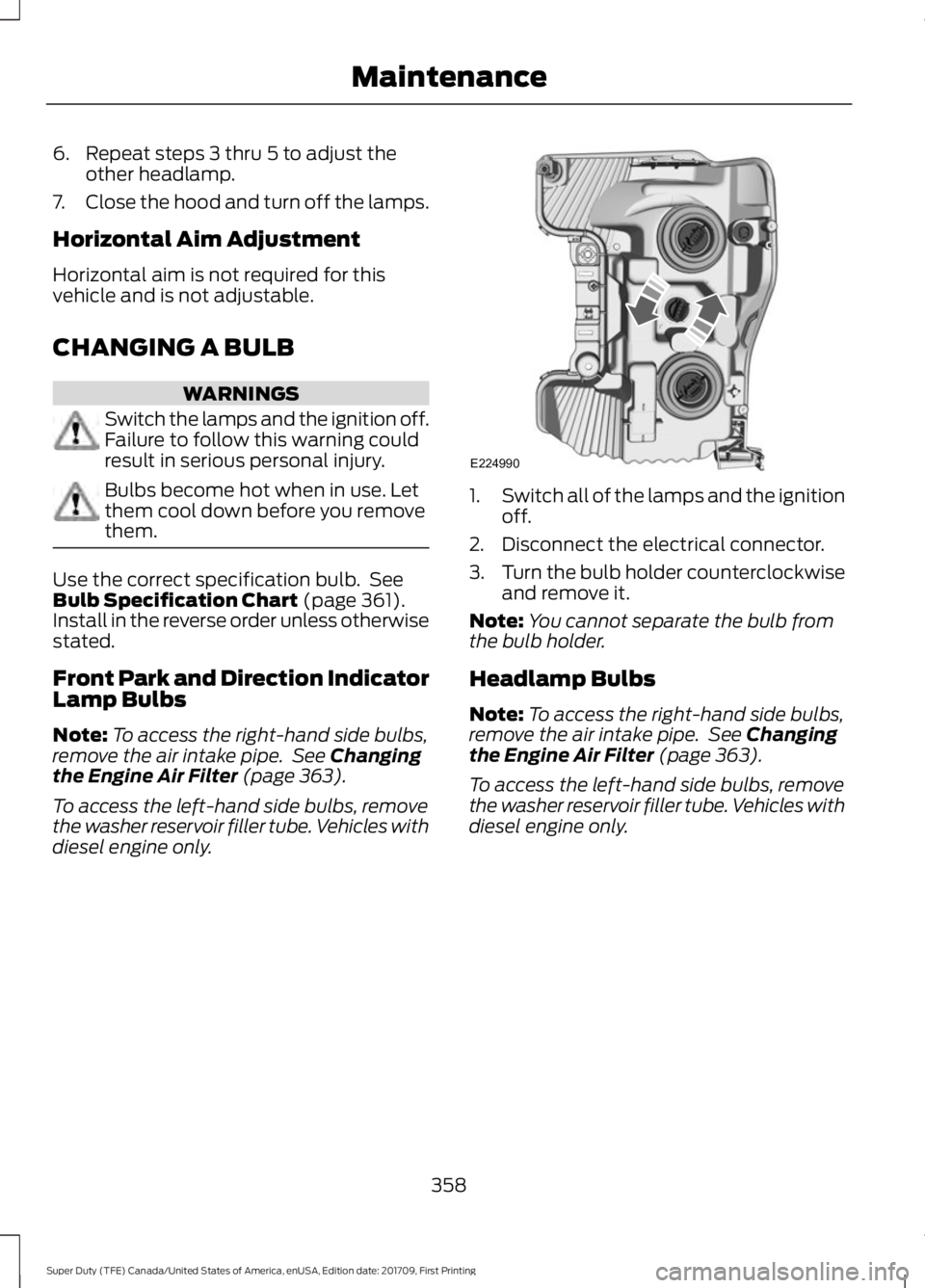
diesel engine only. 1.
Switch all of the lamps and the ignition
off.
2. Disconnect the electrical connector.
3. Turn the bulb holder counterclockwise
and remove it.
Note: You cannot separate the bulb from
the bulb holder.
Headlamp Bulbs
Note: To access the right-hand side bulbs,
remove the air intake pipe. See
Changing
the Engine Air Filter (page 363).
To access the left-hand side bulbs, remove
the washer reservoir filler tube. Vehicles with
diesel engine only.
358
Super Duty (TFE) Canada/United States of America, enUSA, Edition date: 201709, First Printing MaintenanceE224990
Page 362 of 656
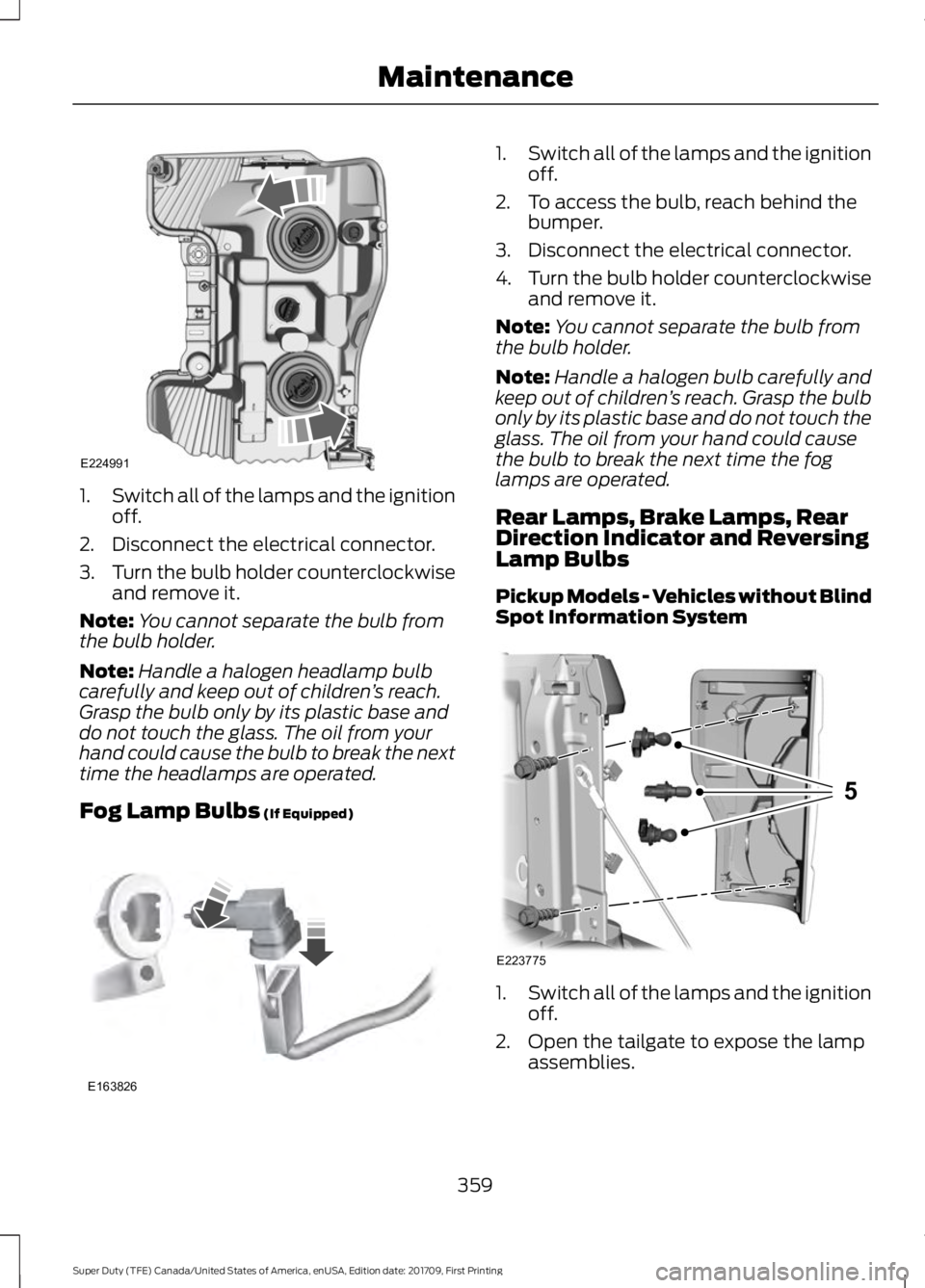
1.
Switch all of the lamps and the ignition
off.
2. Disconnect the electrical connector.
3. Turn the bulb holder counterclockwise
and remove it.
Note: You cannot separate the bulb from
the bulb holder.
Note: Handle a halogen headlamp bulb
carefully and keep out of children ’s reach.
Grasp the bulb only by its plastic base and
do not touch the glass. The oil from your
hand could cause the bulb to break the next
time the headlamps are operated.
Fog Lamp Bulbs (If Equipped) 1.
Switch all of the lamps and the ignition
off.
2. To access the bulb, reach behind the bumper.
3. Disconnect the electrical connector.
4. Turn the bulb holder counterclockwise
and remove it.
Note: You cannot separate the bulb from
the bulb holder.
Note: Handle a halogen bulb carefully and
keep out of children ’s reach. Grasp the bulb
only by its plastic base and do not touch the
glass. The oil from your hand could cause
the bulb to break the next time the fog
lamps are operated.
Rear Lamps, Brake Lamps, Rear
Direction Indicator and Reversing
Lamp Bulbs
Pickup Models - Vehicles without Blind
Spot Information System 1.
Switch all of the lamps and the ignition
off.
2. Open the tailgate to expose the lamp assemblies.
359
Super Duty (TFE) Canada/United States of America, enUSA, Edition date: 201709, First Printing MaintenanceE224991 E163826 E223775
5
Page 363 of 656
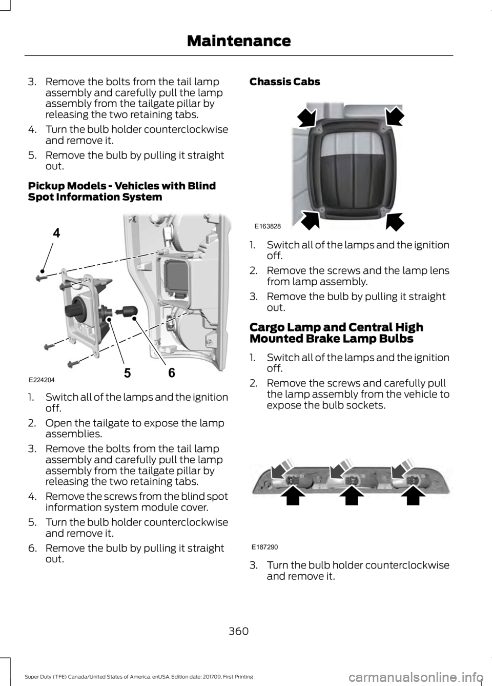
3. Remove the bolts from the tail lamp
assembly and carefully pull the lamp
assembly from the tailgate pillar by
releasing the two retaining tabs.
4. Turn the bulb holder counterclockwise
and remove it.
5. Remove the bulb by pulling it straight out.
Pickup Models - Vehicles with Blind
Spot Information System 1.
Switch all of the lamps and the ignition
off.
2. Open the tailgate to expose the lamp assemblies.
3. Remove the bolts from the tail lamp assembly and carefully pull the lamp
assembly from the tailgate pillar by
releasing the two retaining tabs.
4. Remove the screws from the blind spot
information system module cover.
5. Turn the bulb holder counterclockwise
and remove it.
6. Remove the bulb by pulling it straight out. Chassis Cabs
1.
Switch all of the lamps and the ignition
off.
2. Remove the screws and the lamp lens from lamp assembly.
3. Remove the bulb by pulling it straight out.
Cargo Lamp and Central High
Mounted Brake Lamp Bulbs
1. Switch all of the lamps and the ignition
off.
2. Remove the screws and carefully pull the lamp assembly from the vehicle to
expose the bulb sockets. 3.
Turn the bulb holder counterclockwise
and remove it.
360
Super Duty (TFE) Canada/United States of America, enUSA, Edition date: 201709, First Printing MaintenanceE224204
4
65 E163828 E187290
Page 364 of 656
4. Remove the bulb by pulling it straight
out.
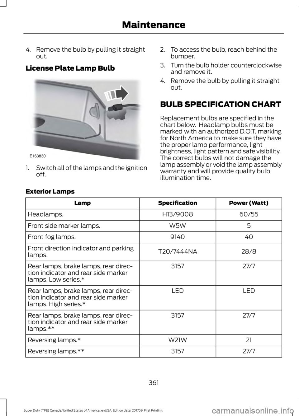
License Plate Lamp Bulb 1.
Switch all of the lamps and the ignition
off. 2. To access the bulb, reach behind the
bumper.
3. Turn the bulb holder counterclockwise
and remove it.
4. Remove the bulb by pulling it straight out.
BULB SPECIFICATION CHART
Replacement bulbs are specified in the
chart below. Headlamp bulbs must be
marked with an authorized D.O.T. marking
for North America to make sure they have
the proper lamp performance, light
brightness, light pattern and safe visibility.
The correct bulbs will not damage the
lamp assembly or void the lamp assembly
warranty and will provide quality bulb
illumination time.
Exterior Lamps Power (Watt)
Specification
Lamp
60/55
H13/9008
Headlamps.
5
W5W
Front side marker lamps.
40
9140
Front fog lamps.
28/8
T20/7444NA
Front direction indicator and parking
lamps.
27/7
3157
Rear lamps, brake lamps, rear direc-
tion indicator and rear side marker
lamps. Low series.*
LED
LED
Rear lamps, brake lamps, rear direc-
tion indicator and rear side marker
lamps. High series.*
27/7
3157
Rear lamps, brake lamps, rear direc-
tion indicator and rear side marker
lamps.**
21
W21W
Reversing lamps.*
27/7
3157
Reversing lamps.**
361
Super Duty (TFE) Canada/United States of America, enUSA, Edition date: 201709, First Printing MaintenanceE163830
Page 371 of 656
3. Drain the diesel fuel conditioner
module. Turn the drain plug
counterclockwise until it stops. Do not
use any tools to loosen the drain plug.
Drain the filter, approximately 0.53 gal
(2 L), into an appropriate container.
Do not re-use the fuel drained from the
module. 4. Disconnect the electrical connector.
5. Fully loosen the bolts securing the
lower portion of the diesel fuel
conditioner module housing.
Note: Do not fully remove the bolts from
the lower portion of the diesel fuel
conditioner module housing.
6. Remove the lower portion of the diesel
fuel conditioner module housing.
368
Super Duty (TFE) Canada/United States of America, enUSA, Edition date: 201709, First Printing Maintenance3
E226212 4
5
6
E226213
Page 372 of 656
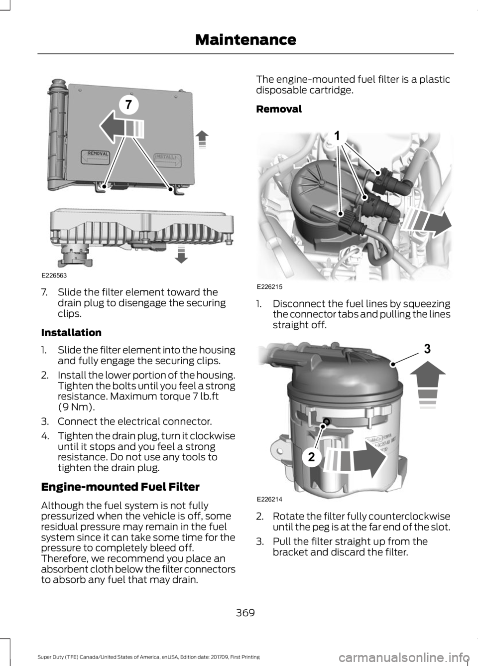
7. Slide the filter element toward the
drain plug to disengage the securing
clips.
Installation
1. Slide the filter element into the housing
and fully engage the securing clips.
2. Install the lower portion of the housing.
Tighten the bolts until you feel a strong
resistance. Maximum torque 7 lb.ft
(9 Nm).
3. Connect the electrical connector.
4. Tighten the drain plug, turn it clockwise
until it stops and you feel a strong
resistance. Do not use any tools to
tighten the drain plug.
Engine-mounted Fuel Filter
Although the fuel system is not fully
pressurized when the vehicle is off, some
residual pressure may remain in the fuel
system since it can take some time for the
pressure to completely bleed off.
Therefore, we recommend you place an
absorbent cloth below the filter connectors
to absorb any fuel that may drain. The engine-mounted fuel filter is a plastic
disposable cartridge.
Removal
1.
Disconnect the fuel lines by squeezing
the connector tabs and pulling the lines
straight off. 2.
Rotate the filter fully counterclockwise
until the peg is at the far end of the slot.
3. Pull the filter straight up from the bracket and discard the filter.
369
Super Duty (TFE) Canada/United States of America, enUSA, Edition date: 201709, First Printing Maintenance7
E226563 E226215
1 E226214
2
3
Page 373 of 656
Installation
1. Install the new filter into the filter
bracket. Turn the filter clockwise to
lock it in place.
2. Reconnect the fuel lines.
370
Super Duty (TFE) Canada/United States of America, enUSA, Edition date: 201709, First Printing Maintenance