2018 FORD F250 SUPER DUTY lock
[x] Cancel search: lockPage 263 of 656
System Lights, Messages and
Audible Alerts
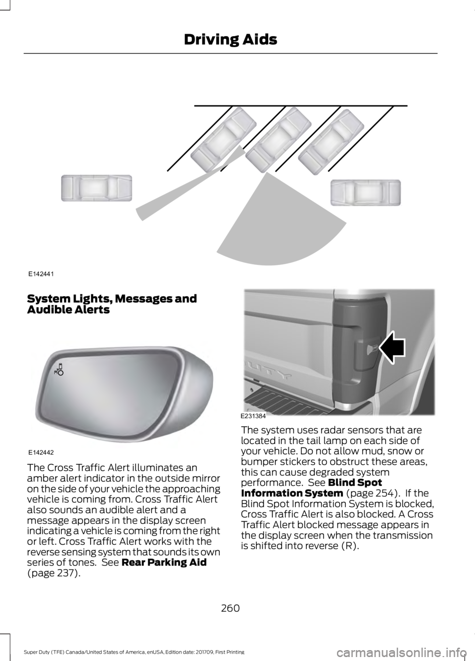
The Cross Traffic Alert illuminates an
amber alert indicator in the outside mirror
on the side of your vehicle the approaching
vehicle is coming from. Cross Traffic Alert
also sounds an audible alert and a
message appears in the display screen
indicating a vehicle is coming from the right
or left. Cross Traffic Alert works with the
reverse sensing system that sounds its own
series of tones. See Rear Parking Aid
(page 237). The system uses radar sensors that are
located in the tail lamp on each side of
your vehicle. Do not allow mud, snow or
bumper stickers to obstruct these areas,
this can cause degraded system
performance. See
Blind Spot
Information System (page 254). If the
Blind Spot Information System is blocked,
Cross Traffic Alert is also blocked. A Cross
Traffic Alert blocked message appears in
the display screen when the transmission
is shifted into reverse (R).
260
Super Duty (TFE) Canada/United States of America, enUSA, Edition date: 201709, First Printing Driving AidsE142441 E142442 E231384
Page 265 of 656

•
Heavy or uneven efforts may be caused
by low power steering fluid. Check for
low power steering pump fluid level
before seeking service by your dealer.
• Do not fill the power steering pump
reservoir above the MAX mark on the
reservoir, as this may result in leaks
from the reservoir.
If the power steering system breaks down
(or if the engine is turned off), you can
steer the vehicle manually, but it takes
more effort.
If the steering wanders or pulls, check for:
• an improperly inflated tire
• uneven tire wear
• loose or worn suspension components
• loose or worn steering components
• improper vehicle alignment
If any steering components are serviced or
replaced, install new fasteners (many are
coated with thread adhesive or have
prevailing torque features which may not
be re-used). Never re-use a bolt or nut.
Torque fasteners to specifications.
A high crown in the road or high crosswinds
may also make the steering seem to
wander or pull.
Adaptive Steering (If Equipped)
Note: The adaptive steering system has
diagnostic checks that continuously monitor
the system. If a fault is detected a message
displays in the information display. If a red
warning message displays, stop your vehicle
as soon as it is safe to do so. The message
may clear if the fault is no longer present. If
an adaptive steering system warning
message appears each time you start your
vehicle, have the system checked as soon
as possible. The adaptive steering system continually
changes the steering ratio with changes to
vehicle speed, optimizing the steering
response in all conditions. The system also
changes when you switch on the
transmission tow/haul feature. When you
select the tow/haul button, the adaptive
steering system reduces vehicle sensitivity
to steering inputs at higher vehicle speeds,
while maintaining the ease of parking and
maneuverability at low speeds.
Note:
The adaptive steering system is
designed with a locking device. With the
lock engaged, the adaptive steering system
remains mechanically locked at a fixed
steering ratio. You may also notice a click
when you switch the vehicle on or after you
switch it off, as the lock disengages or
engages.
Note: If your vehicle loses electrical power
or detects a fault when you are driving, the
system automatically shuts down and you
retain normal steering function with a fixed
steering ratio. During this time it is possible
that the steering wheel may not be straight
when the vehicle is driving straight ahead.
In addition, the driver may notice that the
steering wheel angle required to steer the
vehicle may be different.
Note: During parking maneuvers, the
adaptive steering system balances the driver
work load for various steering wheel inputs
and vehicle loading conditions. Under
extreme operating conditions the system
locking device may engage. This strategy
prevents overheating and permanent
damage to the adaptive steering system.
Typical steering and driving maneuvers
allow the system to cool and return to
normal operation.
262
Super Duty (TFE) Canada/United States of America, enUSA, Edition date: 201709, First Printing Driving Aids
Page 267 of 656
Note:
It is recommended that you turn the
collision warning system off if a snow plow
or similar object is installed in such a way
that it may block the radar sensor. Your
vehicle will remember the selected setting
across key cycles.
Note: When possible, the manufacturer
recommends using the highest sensitivity
setting. If warnings are too frequent, you can
reduce your system's sensitivity. Reduced
sensitivity causes fewer and later system
warnings. See General Information (page
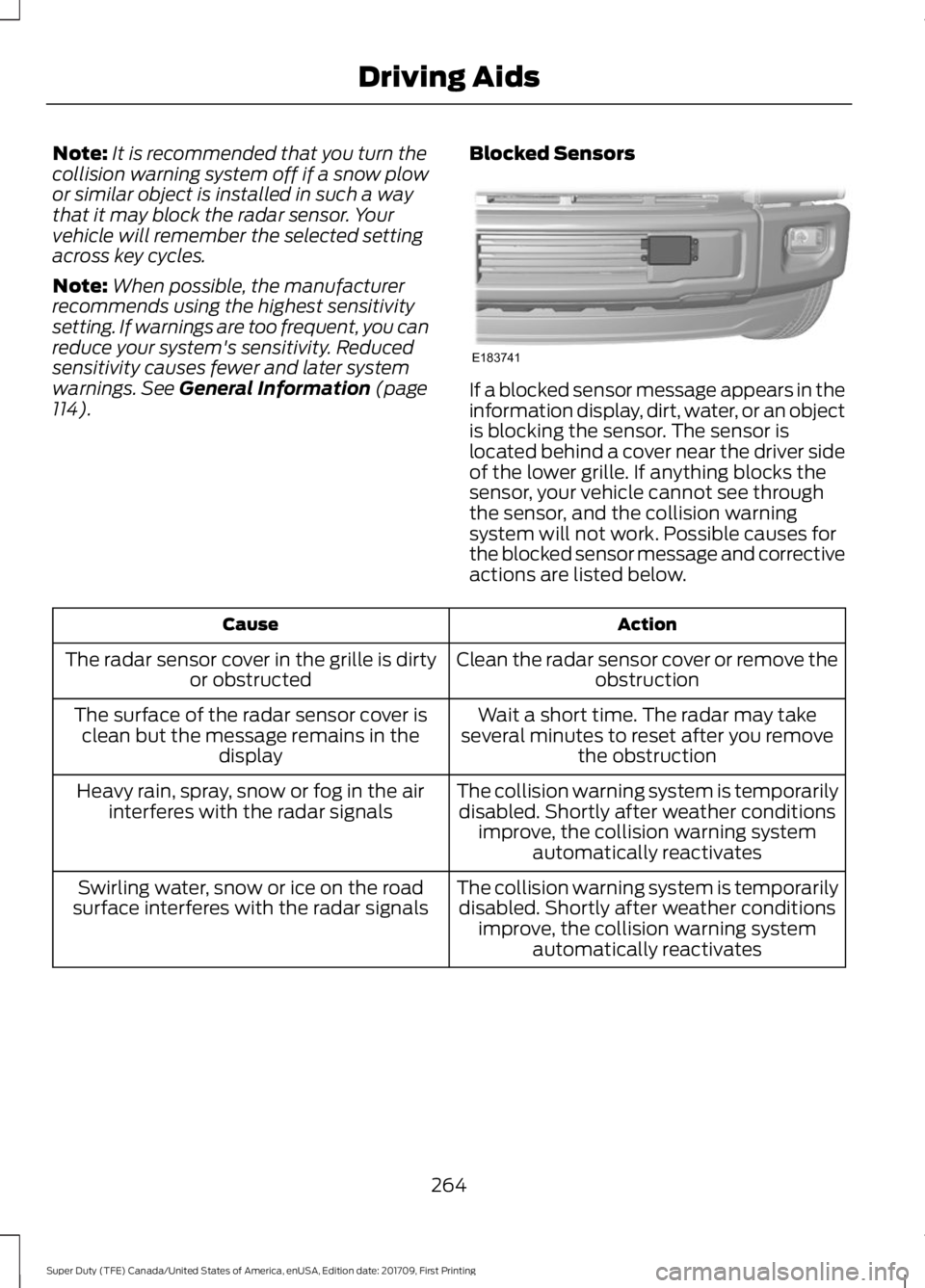
114). Blocked Sensors If a blocked sensor message appears in the
information display, dirt, water, or an object
is blocking the sensor. The sensor is
located behind a cover near the driver side
of the lower grille. If anything blocks the
sensor, your vehicle cannot see through
the sensor, and the collision warning
system will not work. Possible causes for
the blocked sensor message and corrective
actions are listed below.
Action
Cause
Clean the radar sensor cover or remove theobstruction
The radar sensor cover in the grille is dirty
or obstructed
Wait a short time. The radar may take
several minutes to reset after you remove the obstruction
The surface of the radar sensor cover is
clean but the message remains in the display
The collision warning system is temporarilydisabled. Shortly after weather conditions improve, the collision warning system automatically reactivates
Heavy rain, spray, snow or fog in the air
interferes with the radar signals
The collision warning system is temporarilydisabled. Shortly after weather conditions improve, the collision warning system automatically reactivates
Swirling water, snow or ice on the road
surface interferes with the radar signals
264
Super Duty (TFE) Canada/United States of America, enUSA, Edition date: 201709, First Printing Driving AidsE183741
Page 268 of 656
System Limitations
WARNING
The collision warning system
’s brake
support only reduces collision speed
if you first apply your brakes. You
must brake as you would in any typical
braking situation. Due to the nature of radar technology,
there may be certain instances where
vehicles do not provide a collision warning.
These include:
•
Stationary vehicles or vehicles moving
below 6 mph (10 km/h).
• Pedestrians or objects in the roadway.
• Oncoming vehicles in the same lane.
• Severe weather conditions (see
blocked sensor section).
• Debris build-up on the grille near the
headlamps (see blocked sensor
section).
• Small distance to vehicle ahead.
• Large steering wheel and pedal
movements (very active driving style).
Damage to the front end of your vehicle
may alter the radar sensor's coverage area.
This may result in missed or false collision
warnings. Have an authorized dealer check
your radar sensor for proper coverage and
operation.
265
Super Duty (TFE) Canada/United States of America, enUSA, Edition date: 201709, First Printing Driving Aids
Page 275 of 656
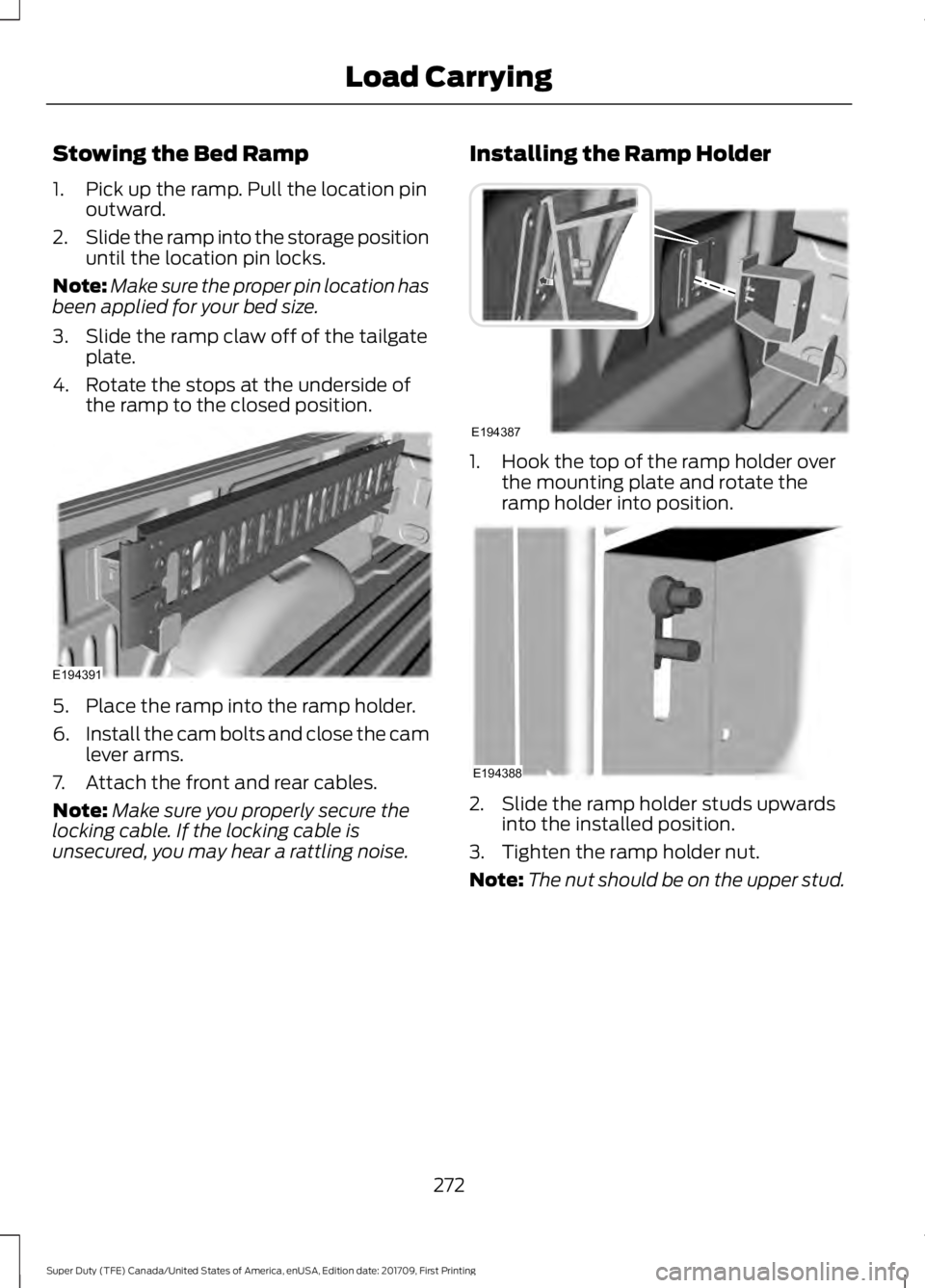
Stowing the Bed Ramp
1. Pick up the ramp. Pull the location pin
outward.
2. Slide the ramp into the storage position
until the location pin locks.
Note: Make sure the proper pin location has
been applied for your bed size.
3. Slide the ramp claw off of the tailgate plate.
4. Rotate the stops at the underside of the ramp to the closed position. 5. Place the ramp into the ramp holder.
6.
Install the cam bolts and close the cam
lever arms.
7. Attach the front and rear cables.
Note: Make sure you properly secure the
locking cable. If the locking cable is
unsecured, you may hear a rattling noise. Installing the Ramp Holder 1. Hook the top of the ramp holder over
the mounting plate and rotate the
ramp holder into position. 2. Slide the ramp holder studs upwards
into the installed position.
3. Tighten the ramp holder nut.
Note: The nut should be on the upper stud.
272
Super Duty (TFE) Canada/United States of America, enUSA, Edition date: 201709, First Printing Load CarryingE194391 E194387 E194388
Page 284 of 656
System is circling something beside the
sticker or system cannot find the sticker:
•
Make sure the rear camera is clean and
the sticker is clearly visible in the
camera image. Clean the camera and
sticker if necessary.
• The camera system uses the entered
measurements to help locate the
sticker. Inaccurate sticker
measurements degrade the system's
ability to locate the sticker. Verify the
measurements entered into the system
are accurate.
• Remove the incorrectly circled label or
decal if possible.
• If you cannot resolve the issue, a new
sticker location should be tried. The
new sticker location must meet the
requirements noted in step 3 of the
setup instructions. Only one sticker can
be placed on the trailer for correct
system function. The previous sticker
must be removed or covered so only
one sticker is visible to the camera.
Calibration
The system monitors various vehicle
parameters to ensure your vehicle is being
driven straight and the trailer straight
behind your vehicle. Any steering input or
trailer movement pauses the calibration.
For best results:
• Use a long, straight and smooth road
when attempting to calibrate.
• Drive straight forward.
• Drive between 4–24 mph
(6– 39 km/h).
System Operation
The following warnings or difficulties may
occur during feature operation. Tips to
resolve them are listed below. The system is not available:
•
The system relies on many
sub-systems in your vehicle to correctly
operate. If those sub-systems are not
correctly operating, the system may
not be available.
•Low battery voltage is one
condition which prevents the
system from operating. Please
make sure the battery is correctly
charged if the system is not
available.
• You may need to drive your vehicle
straight forward above
25 mph
(40 km/h) before the system is
available again.
• If the message still displays, take your
vehicle to an authorized dealer for
service.
Sticker lost:
• Check for the following if you receive
the lost sticker message when using
the system.
•Stop your vehicle as soon as the
message displays.
• Make sure the sticker is visible in
the rear view camera image.
• Clean the sticker and camera to
make sure they are unobstructed.
• Remove any items that may be
blocking the view of the sticker.
Depending on your trailer
configuration and any equipment
mounted to your trailer, it is
possible for the sticker to be
blocked from the view of the
camera as it rotates on the hitch
ball, but not be blocked during
setup. Remove the obstruction if
possible. It may be necessary to
281
Super Duty (TFE) Canada/United States of America, enUSA, Edition date: 201709, First Printing Towing
Page 289 of 656
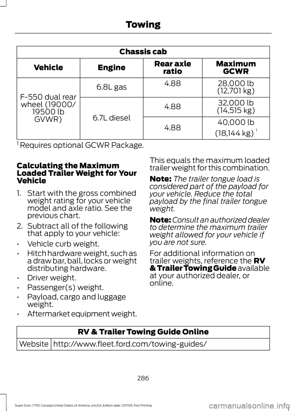
Chassis cab
MaximumGCWR
Rear axle
ratio
Engine
Vehicle
28,000 lb
(12,701 kg)
4.88
6.8L gas
F-550 dual rear wheel (19000/ 19500 lbGVWR) 32,000 lb
(14,515 kg)
4.88
6.7L diesel 40,000 lb
(18,144 kg) 1
4.88
1 Requires optional GCWR Package.
Calculating the Maximum
Loaded Trailer Weight for Your
Vehicle
1. Start with the gross combined weight rating for your vehicle
model and axle ratio. See the
previous chart.
2. Subtract all of the following
that apply to your vehicle:
• Vehicle curb weight.
• Hitch hardware weight, such as
a draw bar, ball, locks or weight
distributing hardware.
• Driver weight.
• Passenger(s) weight.
• Payload, cargo and luggage
weight.
• Aftermarket equipment weight. This equals the maximum loaded
trailer weight for this combination.
Note:
The trailer tongue load is
considered part of the payload for
your vehicle. Reduce the total
payload by the final trailer tongue
weight.
Note: Consult an authorized dealer
to determine the maximum trailer
weight allowed for your vehicle if
you are not sure.
For additional information on
trailer weights, reference the RV
& Trailer Towing Guide available
at your authorized dealer, or
online. RV & Trailer Towing Guide Online
http://www.fleet.ford.com/towing-guides/
Website
286
Super Duty (TFE) Canada/United States of America, enUSA, Edition date: 201709, First Printing Towing
Page 293 of 656
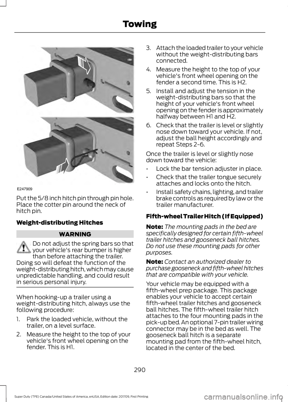
Put the 5/8 inch hitch pin through pin hole.
Place the cotter pin around the neck of
hitch pin.
Weight-distributing Hitches
WARNING
Do not adjust the spring bars so that
your vehicle's rear bumper is higher
than before attaching the trailer.
Doing so will defeat the function of the
weight-distributing hitch, which may cause
unpredictable handling, and could result
in serious personal injury. When hooking-up a trailer using a
weight-distributing hitch, always use the
following procedure:
1. Park the loaded vehicle, without the
trailer, on a level surface.
2. Measure the height to the top of your vehicle's front wheel opening on the
fender. This is H1. 3.
Attach the loaded trailer to your vehicle
without the weight-distributing bars
connected.
4. Measure the height to the top of your vehicle's front wheel opening on the
fender a second time. This is H2.
5. Install and adjust the tension in the weight-distributing bars so that the
height of your vehicle's front wheel
opening on the fender is approximately
halfway between H1 and H2.
6. Check that the trailer is level or slightly
nose down toward your vehicle. If not,
adjust the ball height accordingly and
repeat Steps 2-6.
Once the trailer is level or slightly nose
down toward the vehicle:
• Lock the bar tension adjuster in place.
• Check that the trailer tongue securely
attaches and locks onto the hitch.
• Install safety chains, lighting, and trailer
brake controls as required by law or the
trailer manufacturer.
Fifth-wheel Trailer Hitch (If Equipped)
Note: The mounting pads in the bed are
specifically designed for certain fifth-wheel
trailer hitches and gooseneck ball hitches.
Do not use these mounting pads for other
purposes.
Note: Contact an authorized dealer to
purchase gooseneck and fifth-wheel hitches
that are compatible with your vehicle.
Your vehicle may be equipped with a
fifth-wheel prep package. This package
enables your vehicle to accept certain
fifth-wheel trailer hitches and gooseneck
ball hitches. The fifth-wheel trailer hitch
attaches to the four mounting pads in the
pick-up bed. An optional 7-pin trailer wiring
connector may be in the bed as well. The
gooseneck ball hitch is a separate
mounting pad from the fifth-wheel hitch,
located in the center of the bed.
290
Super Duty (TFE) Canada/United States of America, enUSA, Edition date: 201709, First Printing TowingE247909