2018 FORD F250 SUPER DUTY lock
[x] Cancel search: lockPage 376 of 656
When washing and waxing, park your
vehicle in a shaded area out of direct
sunlight. Always wash your vehicle before
applying wax.
•
Use a quality wax that does not contain
abrasives.
• Follow the manufacturer ’s instructions
to apply and remove the wax.
• Apply a small amount of wax in a
back-and-forth motion, not in circles.
• Do not allow wax to come in contact
with any non-body (low-gloss black)
colored trim. The wax will discolor or
stain the parts over time.
•Roof racks.
• Bumpers.
• Grained door handles.
• Side moldings.
• Mirror housings.
• Windshield cowl area.
• Do not apply wax to glass areas.
• After waxing, your car's paint should
feel smooth, and be free of streaks and
smudges.
CLEANING THE ENGINE
Engines are more efficient when they are
clean because grease and dirt buildup keep
the engine warmer than normal.
When washing:
• Take care when using a power washer
to clean the engine. The high-pressure
fluid could penetrate the sealed parts
and cause damage.
• Do not spray a hot engine with cold
water to avoid cracking the engine
block or other engine components. •
Spray Motorcraft Engine Shampoo and
Degreaser on all parts that require
cleaning and pressure rinse clean. In
Canada, use Motorcraft Engine
Shampoo.
• Never wash or rinse the engine while it
is hot or running; water in the running
engine may cause internal damage.
• Never wash or rinse any ignition coil,
spark plug wire or spark plug well, or
the area in and around these locations.
• Cover the battery, power distribution
box, and air filter assembly to prevent
water damage when cleaning the
engine.
CLEANING THE EXHAUST -
6.7L DIESEL WARNINGS
Failure to maintain the functional
holes, in the tailpipe section of the
exhaust, clean and free of debris or
foreign material may result in the holes
becoming blocked or plugged. Do not
modify or remove the tail-pipe section.
Blocked or plugged holes or
removal/modification of the system could
result in elevated exhaust gas
temperatures which may result in
vehicle/property damage or personal
injury. The normal operating temperature
of the exhaust system is very high.
Never work around or attempt to
repair any part of the exhaust system until
it has cooled. Use special care when
working around the diesel oxidation
catalytic converter and/or the diesel
particulate filter (DPF). The diesel
373
Super Duty (TFE) Canada/United States of America, enUSA, Edition date: 201709, First Printing Vehicle Care
Page 408 of 656
•
To reduce the chances of interference
from another vehicle, perform the
system reset procedure at least three
feet (one meter) away from another
Ford Motor Company vehicle
undergoing the system reset procedure
at the same time.
• Do not wait more than two minutes
between resetting each tire sensor or
the system will time-out and the entire
procedure will have to be repeated on
all four wheels.
• A double horn will sound indicating the
need to repeat the procedure.
Performing the System Reset Procedure
(Single Rear Wheel)
Read the entire procedure before
attempting.
1. Drive the vehicle above 20 mph
(32 km/h) for at least two minutes,
then park in a safe location where you
can easily get to all four tires and have
access to an air pump.
2. Place the ignition in the off position and
keep the key in the ignition.
3. Cycle the ignition to the on position with the engine off.
4. Turn the hazard flashers on then off three times. You must accomplish this
within 10 seconds. If the reset mode
has been entered successfully, the horn
will sound once, the system indicator
will flash and a message is shown in
the information display. If this does not
occur, please try again starting at Step
2. If after repeated attempts to enter
the reset mode, the horn does not
sound, the system indicator does not
flash and no message is shown in the
information display, seek service from
your authorized dealer. 5. Train the tire pressure monitoring
system sensors in the tires using the
following system reset sequence
starting with the left front tire in the
following clockwise order: Left front
(driver's side front tire), Right front
(passenger's side front tire), Right rear
(passenger's side rear tire), Left rear
(driver's side rear tire).
6. Remove the valve cap from the valve stem on the left front tire. Decrease the
air pressure until the horn sounds.
Note: The single horn chirp confirms that
the sensor identification code has been
learned by the module for this position. If a
double horn is heard, the reset procedure
was unsuccessful, and you must repeat it.
7. Remove the valve cap from the valve stem on the right front tire. Decrease
the air pressure until the horn sounds.
8. Remove the valve cap from the valve stem on the right rear tire. Decrease the
air pressure until the horn sounds.
9. Remove the valve cap from the valve stem on the left rear tire. Decrease the
air pressure until the horn sounds.
Training is complete after the horn
sounds for the last tire trained (driver's
side rear tire), the system indicator
stops flashing, and a message is shown
in the information display.
10. Turn the ignition off. If two short horn
beeps are heard, the reset procedure
was unsuccessful and you must
repeat it. If after repeating the
procedure and two short beeps are
heard when the ignition is turned to
off, seek assistance from your
authorized dealer.
405
Super Duty (TFE) Canada/United States of America, enUSA, Edition date: 201709, First Printing Wheels and Tires
Page 413 of 656
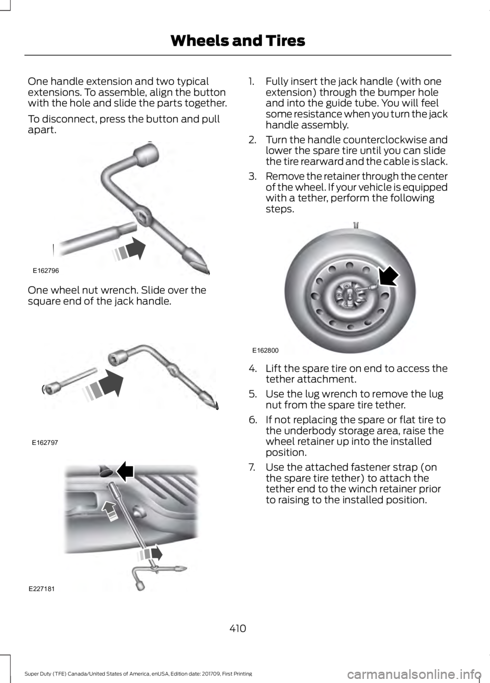
One handle extension and two typical
extensions. To assemble, align the button
with the hole and slide the parts together.
To disconnect, press the button and pull
apart.
One wheel nut wrench. Slide over the
square end of the jack handle. 1. Fully insert the jack handle (with one
extension) through the bumper hole
and into the guide tube. You will feel
some resistance when you turn the jack
handle assembly.
2. Turn the handle counterclockwise and
lower the spare tire until you can slide
the tire rearward and the cable is slack.
3. Remove the retainer through the center
of the wheel. If your vehicle is equipped
with a tether, perform the following
steps. 4.
Lift the spare tire on end to access the
tether attachment.
5. Use the lug wrench to remove the lug nut from the spare tire tether.
6. If not replacing the spare or flat tire to the underbody storage area, raise the
wheel retainer up into the installed
position.
7. Use the attached fastener strap (on the spare tire tether) to attach the
tether end to the winch retainer prior
to raising to the installed position.
410
Super Duty (TFE) Canada/United States of America, enUSA, Edition date: 201709, First Printing Wheels and TiresE162796 E162797 E227181 E162800
Page 414 of 656
Tire Change Procedure
WARNINGS
When one of the front wheels is off
the ground, the transmission alone
will not prevent the vehicle from
moving or slipping off the jack, even if the
transmission is in park (P). To help prevent your vehicle from
moving when changing a wheel, shift
the transmission into park (P), set
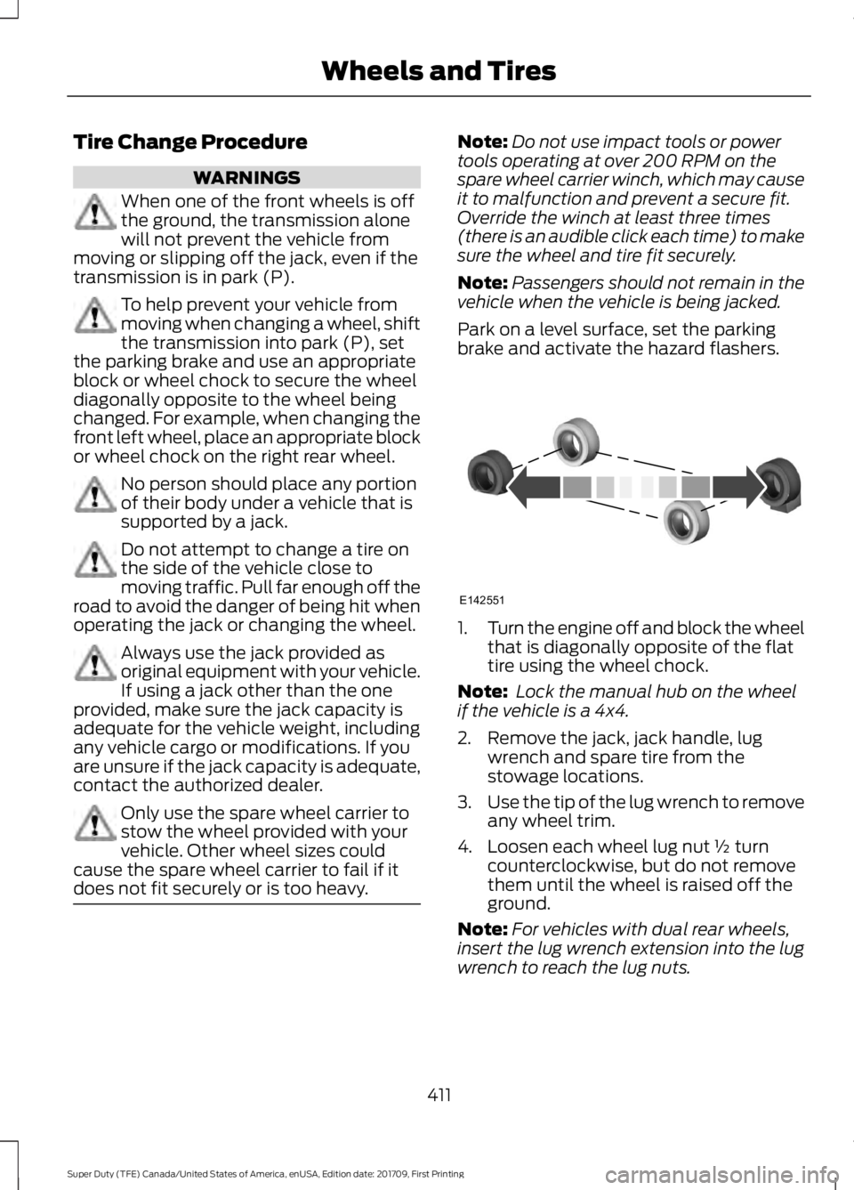
the parking brake and use an appropriate
block or wheel chock to secure the wheel
diagonally opposite to the wheel being
changed. For example, when changing the
front left wheel, place an appropriate block
or wheel chock on the right rear wheel. No person should place any portion
of their body under a vehicle that is
supported by a jack.
Do not attempt to change a tire on
the side of the vehicle close to
moving traffic. Pull far enough off the
road to avoid the danger of being hit when
operating the jack or changing the wheel. Always use the jack provided as
original equipment with your vehicle.
If using a jack other than the one
provided, make sure the jack capacity is
adequate for the vehicle weight, including
any vehicle cargo or modifications. If you
are unsure if the jack capacity is adequate,
contact the authorized dealer. Only use the spare wheel carrier to
stow the wheel provided with your
vehicle. Other wheel sizes could
cause the spare wheel carrier to fail if it
does not fit securely or is too heavy. Note:
Do not use impact tools or power
tools operating at over 200 RPM on the
spare wheel carrier winch, which may cause
it to malfunction and prevent a secure fit.
Override the winch at least three times
(there is an audible click each time) to make
sure the wheel and tire fit securely.
Note: Passengers should not remain in the
vehicle when the vehicle is being jacked.
Park on a level surface, set the parking
brake and activate the hazard flashers. 1.
Turn the engine off and block the wheel
that is diagonally opposite of the flat
tire using the wheel chock.
Note: Lock the manual hub on the wheel
if the vehicle is a 4x4.
2. Remove the jack, jack handle, lug wrench and spare tire from the
stowage locations.
3. Use the tip of the lug wrench to remove
any wheel trim.
4. Loosen each wheel lug nut ½ turn counterclockwise, but do not remove
them until the wheel is raised off the
ground.
Note: For vehicles with dual rear wheels,
insert the lug wrench extension into the lug
wrench to reach the lug nuts.
411
Super Duty (TFE) Canada/United States of America, enUSA, Edition date: 201709, First Printing Wheels and TiresE142551
Page 416 of 656

Rear
Note:
Jack at the specified locations to
avoid damage to the vehicle.
Jacking the Vehicle 1. Turn the jack handle clockwise until
the wheel is completely off the ground
and high enough to install the spare
tire.
2. Remove the lug nuts with the lug wrench.
3. Replace the flat tire with the spare tire,
making sure the valve stem is facing
outward for all front wheels and single
rear wheel vehicles. If you are replacing
an inboard rear tire on dual rear wheel
vehicles, the valve stem must be facing
outward. If you are replacing the
outboard wheel, the valve stem must
be facing inward. Reinstall the lug nuts
until the wheel is snug against the hub.
Do not fully tighten the lug nuts until
the wheel has been lowered.
4. Lower the wheel by turning the jack handle counterclockwise.
5. Remove the jack and fully tighten the lug nuts in the order shown. See
Technical Specifications (page 419).
6. Stow the flat tire. See Stowing the flat or spare tire if the vehicle is equipped
with a spare tire carrier. 7. Stow the jack, jack handle and lug
wrench. Make sure the jack is securely
fastened so it does not rattle when
driving.
8. Unblock the wheels. 8-lug nut torque sequence
10-lug nut torque sequence
413
Super Duty (TFE) Canada/United States of America, enUSA, Edition date: 201709, First Printing Wheels and TiresE162811 E161441
13
4
27
6
5
8 1
2
3
4
5
6
7 8
9
10
E169375 E162820
Page 417 of 656
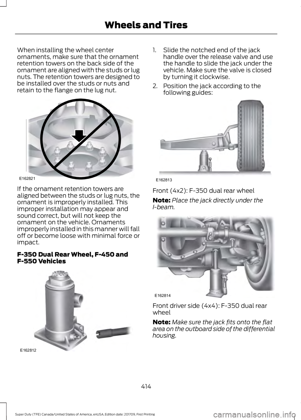
When installing the wheel center
ornaments, make sure that the ornament
retention towers on the back side of the
ornament are aligned with the studs or lug
nuts. The retention towers are designed to
be installed over the studs or nuts and
retain to the flange on the lug nut.
If the ornament retention towers are
aligned between the studs or lug nuts, the
ornament is improperly installed. This
improper installation may appear and
sound correct, but will not keep the
ornament on the vehicle. Ornaments
improperly installed in this manner will fall
off or become loose with minimal force or
impact.
F-350 Dual Rear Wheel, F-450 and
F-550 Vehicles 1. Slide the notched end of the jack
handle over the release valve and use
the handle to slide the jack under the
vehicle. Make sure the valve is closed
by turning it clockwise.
2. Position the jack according to the following guides: Front (4x2): F-350 dual rear wheel
Note:
Place the jack directly under the
I-beam. Front driver side (4x4): F-350 dual rear
wheel
Note:
Make sure the jack fits onto the flat
area on the outboard side of the differential
housing.
414
Super Duty (TFE) Canada/United States of America, enUSA, Edition date: 201709, First Printing Wheels and TiresE162821 E162812 E162813 E162814
Page 419 of 656

2. Use an up-and-down motion with the
jack handle to raise the wheel
completely off the ground.
Note: Hydraulic jacks are equipped with a
pressure release valve that prevents lifting
loads which exceed the jack's rated
capacity.
3. Remove the lug nuts with the lug wrench.
4. Replace the flat tire with the spare tire,
making sure the valve stem is facing
outward on all front an inboard rear
wheels. If you are replacing the
outboard wheel, the valve stem must
be facing inward. Reinstall the lug nuts
until the wheel is snug against the hub.
Do not fully tighten the lug nuts until
the wheel has been lowered.
5. Lower the wheel by slowly turning the release valve counterclockwise.
Opening the release valve slowly will
provide a more controlled rate of
descent.
6. Remove the jack and fully tighten the lug nuts in the order shown. See
Technical Specifications (page 419).
7. Stow the flat tire. See Stowing the flat or spare tire if the vehicle is equipped
with a spare tire carrier.
8. Stow the jack, jack handle and lug wrench. Make sure the jack is securely
fastened so it does not rattle when
driving.
9. Unblock the wheels. 8-lug nut torque sequence
10-lug nut torque sequence
Installing Dual Rear Wheel Ornaments
1. Align the ornament with the lug nuts.
A is the clip and B is the flange.
416
Super Duty (TFE) Canada/United States of America, enUSA, Edition date: 201709, First Printing Wheels and TiresE161441
13
4
27
6
5
8 1
2
3
4
5
6
7 8
9
10
E169375 AB
E162822
Page 421 of 656
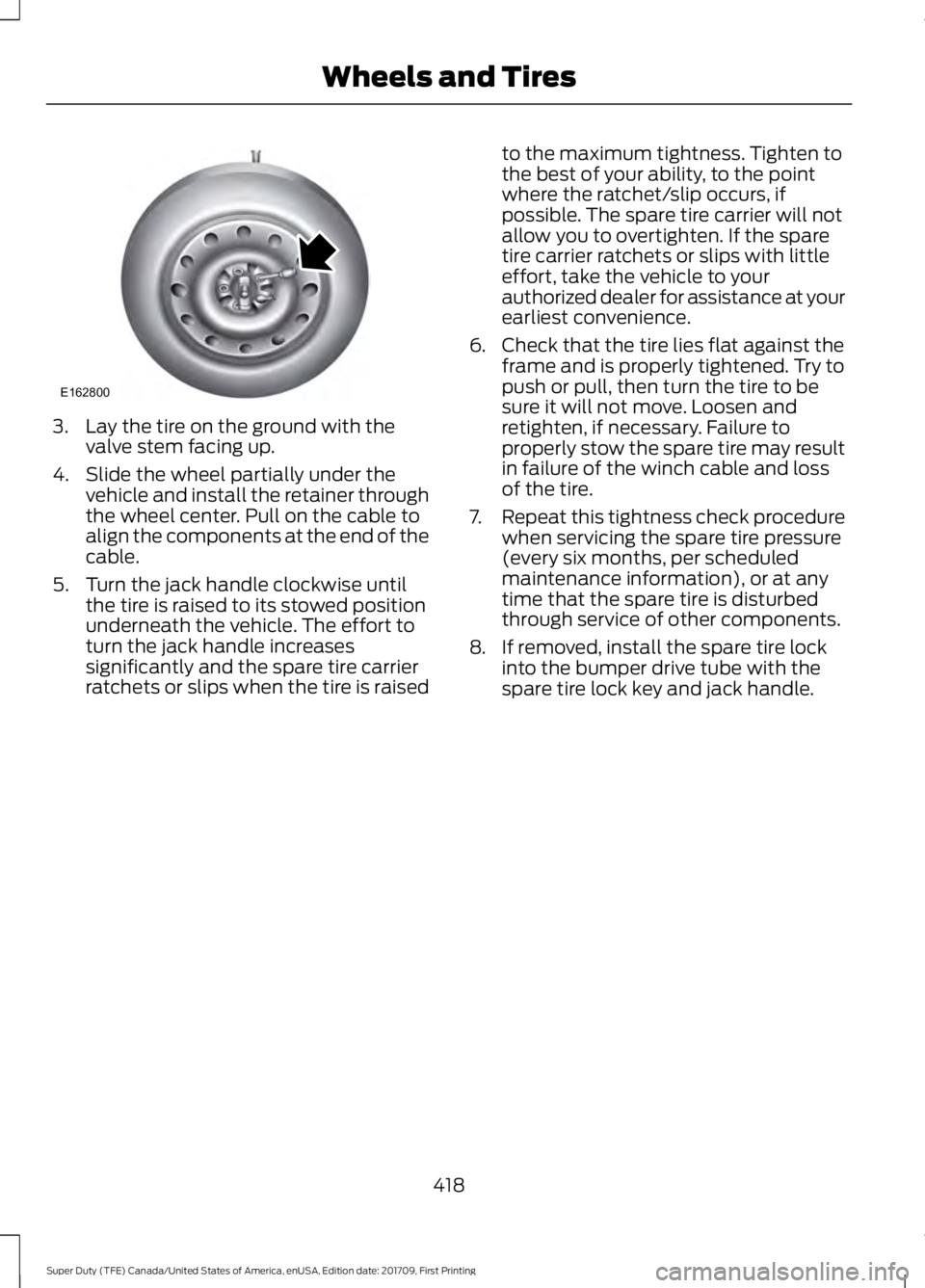
3. Lay the tire on the ground with the
valve stem facing up.
4. Slide the wheel partially under the vehicle and install the retainer through
the wheel center. Pull on the cable to
align the components at the end of the
cable.
5. Turn the jack handle clockwise until the tire is raised to its stowed position
underneath the vehicle. The effort to
turn the jack handle increases
significantly and the spare tire carrier
ratchets or slips when the tire is raised to the maximum tightness. Tighten to
the best of your ability, to the point
where the ratchet/slip occurs, if
possible. The spare tire carrier will not
allow you to overtighten. If the spare
tire carrier ratchets or slips with little
effort, take the vehicle to your
authorized dealer for assistance at your
earliest convenience.
6. Check that the tire lies flat against the frame and is properly tightened. Try to
push or pull, then turn the tire to be
sure it will not move. Loosen and
retighten, if necessary. Failure to
properly stow the spare tire may result
in failure of the winch cable and loss
of the tire.
7. Repeat this tightness check procedure
when servicing the spare tire pressure
(every six months, per scheduled
maintenance information), or at any
time that the spare tire is disturbed
through service of other components.
8. If removed, install the spare tire lock into the bumper drive tube with the
spare tire lock key and jack handle.
418
Super Duty (TFE) Canada/United States of America, enUSA, Edition date: 201709, First Printing Wheels and TiresE162800