Page 437 of 696
Front Turn Signal Lamp
1. Open the hood.
2. Twist the front turn signal lamp socket assembly coun-terclockwise, and then remove the front turn signal
lamp assembly from the lamp housing.
3. Pull the bulb out of the socket and insert the replace- ment bulb.
4. Install the front turn signal lamp socket assembly into the housing, and rotate the front turn signal lamp socket
clockwise to lock it in place.
Front And Rear Side Marker Lamps
1. Remove the three fasteners from the inner wheel linerand carefully peel back liner for access.
2. Firmly grasp the front side marker lamp socket and rotate 1/4 turn counterclockwise to remove it from the
lamp assembly.
Front Turn Signal Lamp Socket
Inner Wheel Liner Fasteners
7
IN CASE OF EMERGENCY 435
Page 438 of 696
3. Remove bulb from the front side marker lamp socketand replace with a new bulb.
4. Install front side marker lamp socket in lamp assembly and rotate 1/4 turn clockwise to lock into place.
5. Position the inner wheel liner in place and install the three fasteners.
Front Fog Lamp — Halogen
1. Remove fasteners from inner wheel liner and carefullypeel back liner for access.
2. Reach through the front fascia to fog lamp housing to access the bulb.
3. Rotate the front fog lamp bulb counterclockwise, and remove the bulb from the front fog lamp housing.
4. Disconnect the bulb from the electrical connector and then connect the replacement bulb.
Front Side Marker Lamp Bulb Removal
Front Fog Lamp Socket
436 IN CASE OF EMERGENCY
Page 439 of 696

CAUTION!
Do not touch the new bulb with your fingers. Oil
contamination will severely shorten bulb life. If the
bulb comes in contact with any oily surface, clean the
bulb with rubbing alcohol.
5. Install the front fog lamp bulb into the front fog lamp housing, and rotate the bulb clockwise to lock it in place.
6. Position the inner wheel liner in place and install fasteners.
Rear Liftgate Mounted Back-Up Lamps And Tail
Lamps (If Bulb Equipped)
1. Raise the liftgate.
2. Use a fiber stick or flat blade screw driver to pry off thebulb access cover on the lower liftgate trim.
3. Back-up lamps/tail lamp (if bulb equipped) are now visible. Rotate socket(s) counter clockwise.
4. Remove/replace bulb(s).
5. Reinstall the socket(s)
6. Reverse process to reinstall the liftgate trim.
Rear Bodyside Mounted Taillamps
1. Raise the liftgate.
2. Remove two torx head screws on bodyside lamp using a T30 screwdriver.
3. Remove lamp from vehicle body and locate bulb socket on rear of lamp. Rotate socket counter-clockwise.
4. Remove/replace bulb(s).
5. Reinstall the socket(s)
6. Reverse process to reinstall the lamp onto vehicle.
Center High-Mounted Stop Lamp (CHMSL)
The center high-mounted stop lamp is an LED assembly.
See your authorized dealer for replacement.
Rear License Lamp
The rear license lamps are LED. See your authorized dealer
for replacement.
7
IN CASE OF EMERGENCY 437
Page 447 of 696
Cavity Cartridge FuseBlade FuseDescription
F90 – – Not Used
F91 –15 Amp Blue Front Ventilated Seats/Heated Steering Wheel
F92 – 5 Amp Tan Security Gateway
F93 – – Not Used
F94 40 Amp Green –ESC Motor Pump
F95A –10 Amp Red USB Charge Port — ACC RUN
F95B –10 Amp Red Selectable Fuse Location
F96 –10 Amp Red Occupant Restraint Controller (ORC) (Airbag)
F97 –10 Amp Red Occupant Restraint Controller (ORC) (Airbag)
F98 –15 Amp Blue Left HID Headlamp
F99 30 Amp Pink –Trailer Tow Module - If Equipped
F100A –10 Amp Red AHLM
F100B –10 Amp Red Rear Camera/LBSS/RBSS/CVPM/Humidity
Sensor/In Vehicle Temperature Sensor
Circuit Breakers
CB1 25 Amp Power Seats (Driver)
CB2 25 Amp * Power Seats (Pass)
CB3 25 Amp FRT PWR Window W/O Door Nodes + RR PWR
Window Lockout
* 30A mini fuse is substituted for 25A Circuit Breaker.
7
IN CASE OF EMERGENCY 445
Page 448 of 696

JACKING AND TIRE CHANGING — IF EQUIPPED
WARNING!
•Do not attempt to change a tire on the side of the
vehicle close to moving traffic. Pull far enough off
the road to avoid the danger of being hit when
operating the jack or changing the wheel.
• Being under a jacked-up vehicle is dangerous. The
vehicle could slip off the jack and fall on you. You
could be crushed. Never put any part of your body
under a vehicle that is on a jack. If you need to get
under a raised vehicle, take it to a service center
where it can be raised on a lift.
• The jack is designed to be used as a tool for changing
tires only. The jack should not be used to lift the
vehicle for service purposes. The vehicle should be
jacked on a firm level surface only. Avoid ice or
slippery areas.
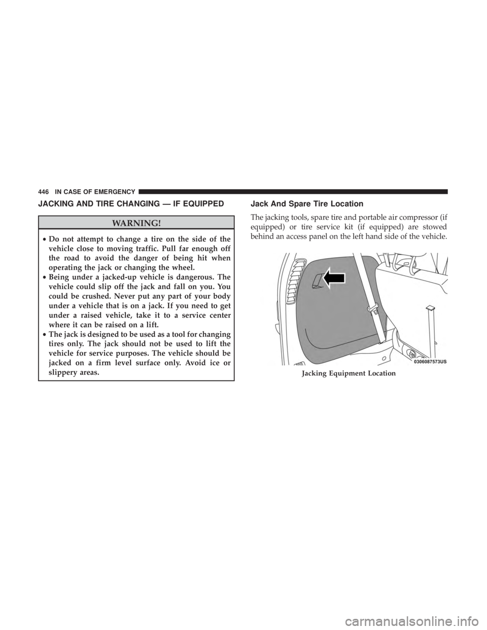
Jack And Spare Tire Location
The jacking tools, spare tire and portable air compressor (if
equipped) or tire service kit (if equipped) are stowed
behind an access panel on the left hand side of the vehicle.
Jacking Equipment Location
446 IN CASE OF EMERGENCY
Page 450 of 696

Preparations For Jacking
1. Park the vehicle on a firm, level surface. Avoid ice orslippery areas.
WARNING!
Do not attempt to change a tire on the side of the
vehicle close to moving traffic. Pull far enough off the
road to avoid being hit when operating the jack or
changing the wheel.
2. Turn on the Hazard Warning flasher.
3. Apply the parking brake.
4. Place the gear selector into PARK.
5. Place the ignition in OFF mode.
6. Block both the front and rear of the wheel diagonally opposite the jacking position. For example, if the right
front wheel is being changed, block the left rear wheel.
NOTE:Passengers should not remain in the
vehicle when the vehicle is being jacked.
Jacking Instructions
WARNING!
Carefully follow these tire changing warnings to help
prevent personal injury or damage to your vehicle:
• Always park on a firm, level surface as far from the
edge of the roadway as possible before raising the
vehicle.
• Turn on the Hazard Warning flasher.
• Block the wheel diagonally opposite the wheel to be
raised.
• Apply the parking brake firmly and set the transmis-
sion in PARK.
• Do not let any passenger sit in the vehicle when it is
on a jack.
• Do not get under the vehicle when it is on a jack. If
you need to get under a raised vehicle, take it to a
service center where it can be raised on a lift.
• Only use the jack in the positions indicated and for
lifting this vehicle during a tire change.
• If working on or near a roadway, be extremely
careful of motor traffic.
448 IN CASE OF EMERGENCY
Page 451 of 696
CAUTION!
Do not attempt to raise the vehicle by jacking on
locations other than those indicated in the Jacking
Instructions for this vehicle.
NOTE: Refer to “Tires” in “Servicing And Maintenance �for
information about the inflatable spare tire, its use, and
operation. 1. Loosen (but do not remove) the wheel lug nuts by
turning them to the left one turn while the wheel is still
on the ground.
2. There are two jack engagement locations on each side of the vehicle body. These locations are on the sill flange of
the vehicle body.
Jack Warning LabelExtending The Wrench
7
IN CASE OF EMERGENCY 449
Page 454 of 696

CAUTION!
Do not attempt to raise the vehicle by jacking on
locations other than those indicated.
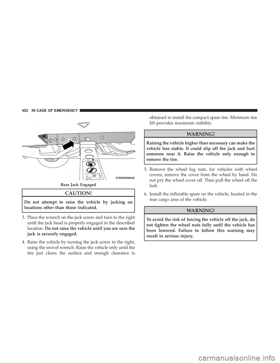
3. Place the wrench on the jack screw and turn to the right until the jack head is properly engaged in the described
location. Do not raise the vehicle until you are sure the
jack is securely engaged.
4. Raise the vehicle by turning the jack screw to the right, using the swivel wrench. Raise the vehicle only until the
tire just clears the surface and enough clearance is obtained to install the compact spare tire. Minimum tire
lift provides maximum stability.
WARNING!
Raising the vehicle higher than necessary can make the
vehicle less stable. It could slip off the jack and hurt
someone near it. Raise the vehicle only enough to
remove the tire.
5. Remove the wheel lug nuts, for vehicles with wheel covers, remove the cover from the wheel by hand. Do
not pry the wheel cover off. Then pull the wheel off the
hub.
6. Install the inflatable spare on the vehicle, located in the rear cargo area of the vehicle.
WARNING!
To avoid the risk of forcing the vehicle off the jack, do
not tighten the wheel nuts fully until the vehicle has
been lowered. Failure to follow this warning may
result in serious injury.
Rear Jack Engaged
452 IN CASE OF EMERGENCY