Page 303 of 614
If the system is set when the vehicle speed is below 20 mph
(32 km/h), the set speed shall be defaulted to 20 mph
(32 km/h). If the system is set when the vehicle speed is
above 20 mph (32 km/h), the set speed shall be the current
speed of the vehicle.
NOTE:ACC cannot be set if there is a stationary vehicle in
front of your vehicle in close proximity.
Remove your foot from the accelerator pedal, after the
ACC has been set. If you do not, the vehicle may continue
to accelerate beyond the set speed. If this occurs:
• The message “ACC DRIVER OVERRIDE” will display
in the instrument cluster display.
• The system will not be controlling the distance between
your vehicle and the vehicle ahead. The vehicle speed
will only be determined by the position of the accelera-
tor pedal.
To Cancel
The following conditions cancel the system:
• The brake pedal is applied.
• The CANC (cancel) button is pushed.
• An Anti-Lock Brake System (ABS) event occurs. •
The gear selector is removed from the DRIVE position.
• The Electronic Stability Control/Traction Control Sys-
tem (ESC/TCS) activates.
• The vehicle parking brake is applied.
• Driver seatbelt is unbuckled at low speeds.
• Driver door is opened at low speeds.
To Turn Off
The system will turn off and clear the set speed in memory
if:
•The Adaptive Cruise Control (ACC) on/off button is
pushed.
• The Normal (Fixed Speed) Cruise Control on/off button
is pushed.
• The ignition is turned OFF.
To Resume
If there is a set speed in memory push the RES (resume)
button and then remove your foot from the accelerator
pedal. The instrument cluster display will display the last
set speed.
6
STARTING AND OPERATING 301
Page 339 of 614
feature. The system will also continuously perform the
dynamic vehicle calibration to account for differences
such as over or under inflated tires and new tires.
Enabling And Disabling The ParkSense Active Park
Assist System
The ParkSense Active Park Assist system can be
enabled and disabled with the ParkSense Active
Park Assist switch, located on the switch panel
below the Uconnect display.
To enable the ParkSense Active Park Assist system, push the
ParkSense Active Park Assist switch once (LED turns on).
To disable the ParkSense Active Park Assist system, push the
ParkSense Active Park Assist switch again (LED turns off).
The ParkSense Active Park Assist system will turn off
automatically for any of the following conditions:
• The parking maneuver is completed.
• Vehicle speed greater than 18 mph (30 km/h) when
searching for a parking space.
• Vehicle speed greater than 5 mph (7 km/h) during active
steering guidance into the parking space. •
Touching the steering wheel during active steering guid-
ance into the parking space.
• Pushing the ParkSense Front and Rear Park Assist
switch.
• The driver ’s door is opened.
• The liftgate is opened.
• Electronic Stability Control/Anti-lock Braking System
intervention.
• The ParkSense Active Park Assist system will allow a
maximum of eight shifts between DRIVE and REVERSE.
If the maneuver cannot be completed within eight shifts,
the system will cancel and the instrument cluster display
will instruct the driver to complete the maneuver manu-
ally.
The ParkSense Active Park Assist system will only operate
and search for a parking space when the following condi-
tions are present:
• The gear position is in DRIVE.
• The ignition is in the RUN position.
• The ParkSense Active Park Assist switch is activated.
• The driver ’s door is closed.
6
STARTING AND OPERATING 337
Page 362 of 614
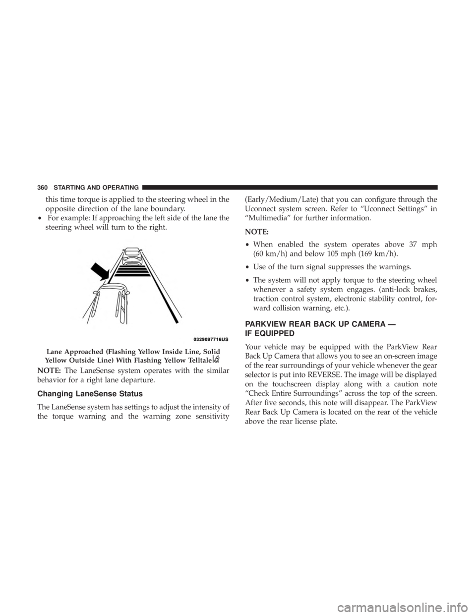
this time torque is applied to the steering wheel in the
opposite direction of the lane boundary.
•For example: If approaching the left side of the lane the
steering wheel will turn to the right.
NOTE: The LaneSense system operates with the similar
behavior for a right lane departure.
Changing LaneSense Status
The LaneSense system has settings to adjust the intensity of
the torque warning and the warning zone sensitivity (Early/Medium/Late) that you can configure through the
Uconnect system screen. Refer to “Uconnect Settings” in
“Multimedia” for further information.
NOTE:
•
When enabled the system operates above 37 mph
(60 km/h) and below 105 mph (169 km/h).
• Use of the turn signal suppresses the warnings.
• The system will not apply torque to the steering wheel
whenever a safety system engages. (anti-lock brakes,
traction control system, electronic stability control, for-
ward collision warning, etc.).
PARKVIEW REAR BACK UP CAMERA —
IF EQUIPPED
Your vehicle may be equipped with the ParkView Rear
Back Up Camera that allows you to see an on-screen image
of the rear surroundings of your vehicle whenever the gear
selector is put into REVERSE. The image will be displayed
on the touchscreen display along with a caution note
“Check Entire Surroundings” across the top of the screen.
After five seconds, this note will disappear. The ParkView
Rear Back Up Camera is located on the rear of the vehicle
above the rear license plate.Lane Approached (Flashing Yellow Inside Line, Solid
Yellow Outside Line) With Flashing Yellow Telltale
360 STARTING AND OPERATING
Page 378 of 614
CAUTION!
•Always check the depth of the standing water before
driving through it. Never drive through standing
water that is deeper than the bottom of the tire rims
mounted on the vehicle.
• Determine the condition of the road or the path that
is under water and if there are any obstacles in the
way before driving through the standing water.
• Do not exceed 5 mph (8 km/h) when driving through
standing water. This will minimize wave effects.
• Driving through standing water may cause damage
to your vehicle’s drivetrain components. Always in-
spect your vehicle’s fluids (i.e., engine oil, transmis-
sion, axle, etc.) for signs of contamination (i.e., fluid
that is milky or foamy in appearance) after driving
through standing water. Do not continue to operate
the vehicle if any fluid appears contaminated, as this
may result in further damage. Such damage is not
covered by the New Vehicle Limited Warranty.
• Getting water inside your vehicle’s engine can cause
it to lock up and stall out, and cause serious internal
damage to the engine. Such damage is not covered by
the New Vehicle Limited Warranty.
376 STARTING AND OPERATING
Page 388 of 614
Replacing Exterior Bulbs
Halogen Headlamps
1. Reach behind the headlamp housing to access theheadlamp bulb cap.
2. Firmly grasp the headlamp bulb cap and rotate it counterclockwise to unlock it.
3. Firmly grasp the headlamp bulb socket assembly and rotate counterclockwise to remove from the housing. 4. Disconnect the bulb from the electrical connector and
then connect the replacement bulb.
Headlamp Bulb Cap
Headlamp Bulb Socket
386 IN CASE OF EMERGENCY
Page 389 of 614
CAUTION!
Do not touch the new bulb with your fingers. Oil
contamination will severely shorten bulb life. If the
bulb comes in contact with any oily surface, clean the
bulb with rubbing alcohol.
5. Install the bulb and connector assembly into the head- lamp housing and rotate clockwise to lock it in place.
6. Install the headlamp bulb cap in the headlamp housing and rotate clockwise to lock it in place.
Front Turn Signal Lamp
1. Open the hood.
2. Twist the front turn signal lamp socket assembly coun-terclockwise, and then remove the front turn signal
lamp assembly from the lamp housing.
3. Pull the bulb out of the socket and insert the replace- ment bulb.
4. Install the front turn signal lamp socket assembly into the housing, and rotate the front turn signal lamp socket
clockwise to lock it in place.
Headlamp Bulb
Front Turn Signal Lamp Socket
7
IN CASE OF EMERGENCY 387
Page 390 of 614
Front And Rear Side Marker Lamps
1. Remove the three fasteners from the inner wheel linerand carefully peel back liner for access.
2. Firmly grasp the front side marker lamp socket and rotate 1/4 turn counterclockwise to remove it from the
lamp assembly. 3. Remove bulb from the front side marker lamp socket
and replace with a new bulb.
4. Install front side marker lamp socket in lamp assembly and rotate 1/4 turn clockwise to lock into place.
5. Position the inner wheel liner in place and install the three fasteners.
Inner Wheel Liner Fasteners
Front Side Marker Lamp Bulb Removal
388 IN CASE OF EMERGENCY
Page 391 of 614
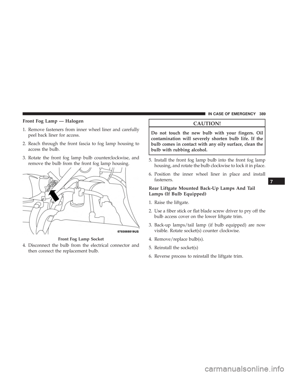
Front Fog Lamp — Halogen
1. Remove fasteners from inner wheel liner and carefullypeel back liner for access.
2. Reach through the front fascia to fog lamp housing to access the bulb.
3. Rotate the front fog lamp bulb counterclockwise, and remove the bulb from the front fog lamp housing.
4. Disconnect the bulb from the electrical connector and then connect the replacement bulb.
CAUTION!
Do not touch the new bulb with your fingers. Oil
contamination will severely shorten bulb life. If the
bulb comes in contact with any oily surface, clean the
bulb with rubbing alcohol.
5. Install the front fog lamp bulb into the front fog lamp housing, and rotate the bulb clockwise to lock it in place.
6. Position the inner wheel liner in place and install fasteners.
Rear Liftgate Mounted Back-Up Lamps And Tail
Lamps (If Bulb Equipped)
1. Raise the liftgate.
2. Use a fiber stick or flat blade screw driver to pry off thebulb access cover on the lower liftgate trim.
3. Back-up lamps/tail lamp (if bulb equipped) are now visible. Rotate socket(s) counter clockwise.
4. Remove/replace bulb(s).
5. Reinstall the socket(s)
6. Reverse process to reinstall the liftgate trim.
Front Fog Lamp Socket
7
IN CASE OF EMERGENCY 389