Page 392 of 614

Rear Bodyside Mounted Taillamps
1. Raise the liftgate.
2. Remove two torx head screws on bodyside lamp usinga T30 screwdriver.
3. Remove lamp from vehicle body and locate bulb socket on rear of lamp. Rotate socket counter-clockwise.
4. Remove/replace bulb(s).
5. Reinstall the socket(s)
6. Reverse process to reinstall the lamp onto vehicle.
Center High-Mounted Stop Lamp (CHMSL)
The center high-mounted stop lamp is an LED assembly.
See your authorized dealer for replacement.
Rear License Lamp
The rear license lamps are LED. See your authorized dealer
for replacement.
FUSES
WARNING!
• When replacing a blown fuse, always use an appro-
priate replacement fuse with the same amp rating as
the original fuse. Never replace a fuse with another
fuse of higher amp rating. Never replace a blown
fuse with metal wires or any other material. Do not
place a fuse inside a circuit breaker cavity or vice
versa. Failure to use proper fuses may result in
serious personal injury, fire and/or property damage.
• Before replacing a fuse, make sure that the ignition is
off and that all the other services are switched off
and/or disengaged.
• If the replaced fuse blows again, contact an autho-
rized dealer.
• If a general protection fuse for safety systems (air
bag system, braking system), power unit systems
(engine system, transmission system) or steering
system blows, contact an authorized dealer.
390 IN CASE OF EMERGENCY
Page 394 of 614
Underhood Fuses
The Power Distribution Center is located in the engine
compartment near the battery. This center contains car-
tridge fuses, mini-fuses, micro-fuses, circuit breakers and
relays. A label that identifies each component is printed on
the inside of the cover.
Before any procedure is done on the PDC, make sure
engine is turned off.
Remove the cover by unlatching the two locks located at
each side of the PDC cover, avoid the usage of screw
drivers or any other tool to remove the cover, since they
may apply excessive force and result on a broken/
damaged part.After service is done, secure the cover with its two locks.
Cavity
Cartridge Fuse Blade FuseDescription
F06 –15 Amp Blue Low Temp Active Pump
F07 –25 Amp Clear Ignition Coil/Fuel Injector
F08 –25 Amp Clear Amplifier / ANC
F09 ––Not Used
F10 –15 Amp Blue High Temp Aux Pump &
HV Electric Coolant Htr Enable
Power Distribution Center
392 IN CASE OF EMERGENCY
Page 395 of 614
CavityCartridge Fuse Blade FuseDescription
F11 –15 Amp Blue ELCM / FTIV
F12 –5 Amp Tan Battery Sensor (IBS)
F13 ––Not Used
F14A –10 Amp Red Media Hub 1, 2, 3
F14B – Pwr Lumbar Switch
F15 40 Amp Green –CBC / Power Locks
F16 –20 Amp Yellow ECM
F17 ––Not Used
F18 40 Amp Green –CBC Feed #4 (Exterior
Lights #1)
F19 ––Not Used
F20 –10 Amp RedLow Temp Passive Pump
F21 20 Amp Blue –PIM - Park PAWL Motor
F22 ––Not Used
F23 ––Not used
F24 –20 Amp Yellow RR Wiper
F25A –10 Amp Red Handsfree (Lt & Rt Rear
Door Release Module)
F25B – Active Grill Shutter
F26 40 Amp Green –Front HVAC Blower Motor
7
IN CASE OF EMERGENCY 393
Page 403 of 614

Preparations For Jacking
1. Park the vehicle on a firm, level surface. Avoid ice orslippery areas.
WARNING!
Do not attempt to change a tire on the side of the
vehicle close to moving traffic. Pull far enough off the
road to avoid being hit when operating the jack or
changing the wheel.
2. Turn on the Hazard Warning flasher.
3. Apply the parking brake.
4. Place the gear selector into PARK.
5. Place the ignition in OFF mode.
6. Block both the front and rear of the wheel diagonally opposite the jacking position. For example, if the right
front wheel is being changed, block the left rear wheel.
NOTE:Passengers should not remain in the
vehicle when the vehicle is being jacked.
Jacking Instructions
WARNING!
Carefully follow these tire changing warnings to help
prevent personal injury or damage to your vehicle:
• Always park on a firm, level surface as far from the
edge of the roadway as possible before raising the
vehicle.
• Turn on the Hazard Warning flasher.
• Block the wheel diagonally opposite the wheel to be
raised.
• Set the parking brake firmly and set the transmission
in PARK.
• Do not let any passenger sit in the vehicle when it is
on a jack.
• Do not get under the vehicle when it is on a jack. If
you need to get under a raised vehicle, take it to a
service center where it can be raised on a lift.
• Only use the jack in the positions indicated and for
lifting this vehicle during a tire change.
• If working on or near a roadway, be extremely
careful of motor traffic.
7
IN CASE OF EMERGENCY 401
Page 408 of 614

3. Align the valve notch in the wheel cover with the valvestem on the wheel. Install the cover by hand, snapping
the cover over the two lug nuts. Do not use a hammer or
excessive force to install the cover.
4. Install the remaining lug nuts with the cone shaped end of the nut toward the wheel. Lightly tighten the lug
nuts.
WARNING!
To avoid the risk of forcing the vehicle off the jack, do
not tighten the wheel nuts fully until the vehicle has
been lowered. Failure to follow this warning may
result in serious injury.
5. Lower the vehicle to the ground by turning the jack handle counterclockwise.
6. Finish tightening the lug nuts. Push down on the wrench while at the end of the handle for increased
leverage. Tighten the lug nuts in a star pattern until each
nut has been tightened twice. Refer to “Torque Specifi-
cations” in “Technical Specifications” for proper wheel
lug nut torque. If in doubt about the correct tightness,
have them checked with a torque wrench by an autho-
rized dealer or at a service station.
7. After 25 miles (40 km) check the lug nut torque with a torque wrench to ensure that all lug nuts are properly
seated against the wheel.
Tire And Wheel Cover Or Center Cap
1 — Valve Stem 4 — Wheel Cover
2 — Valve Notch 5 — Mounting Stud
3 — Wheel Lug Nut 406 IN CASE OF EMERGENCY
Page 409 of 614

Vehicles Without Wheel Covers
1. Mount the road tire on the axle.
2. Install the remaining lug nuts with the cone shaped endof the nut toward the wheel. Lightly tighten the lug
nuts.
WARNING!
To avoid the risk of forcing the vehicle off the jack, do
not tighten the wheel nuts fully until the vehicle has
been lowered. Failure to follow this warning may
result in serious injury.
3. Lower the vehicle to the ground by turning the jack handle counterclockwise.
4. Finish tightening the lug nuts. Push down on the wrench while at the end of the handle for increased
leverage. Tighten the lug nuts in a star pattern until each
nut has been tightened twice. Refer to “Torque Specifi-
cations” in the “Technical Specifications” section for
proper wheel lug nut torque. If in doubt about the
correct tightness, have them checked with a torque
wrench by your authorized dealer or at a service station. 5. After 25 miles (40 km) check the lug nut torque with a
torque wrench to ensure that all lug nuts are properly
seated against the wheel.
TIRE SERVICE KIT — IF EQUIPPED
Your vehicle may be equipped with a Tire Service Kit.
Small punctures up to 1/4 inch (6 mm) in the tire tread can
be sealed with Tire Service Kit. Foreign objects (e.g., screws
or nails) should not be removed from the tire. Tire Service
Kit can be used in outside temperatures down to approxi-
mately -4°F (-20°C). This kit will provide a temporary tire
seal, allowing you to drive your vehicle up to 100 miles
(160 km) with a maximum speed of 50 mph (80 km/h).
Tire Service Kit Storage
The Tire Service Kit is secured with a strap and is stored in
the storage bin located behind the rear cargo trim panel.
7
IN CASE OF EMERGENCY 407
Page 447 of 614

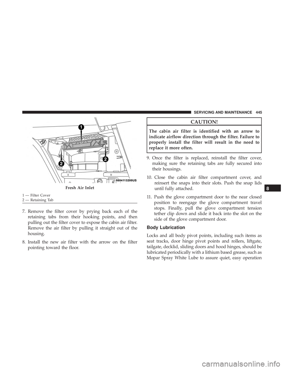
7. Remove the filter cover by prying back each of theretaining tabs from their hooking points, and then
pulling out the filter cover to expose the cabin air filter.
Remove the air filter by pulling it straight out of the
housing.
8. Install the new air filter with the arrow on the filter pointing toward the floor.
CAUTION!
The cabin air filter is identified with an arrow to
indicate airflow direction through the filter. Failure to
properly install the filter will result in the need to
replace it more often.
9. Once the filter is replaced, reinstall the filter cover, making sure the retaining tabs are fully secured into
their housings.
10. Close the cabin air filter compartment cover, and reinsert the snaps into their slots. Push the snap lids
until fully attached.
11. Push the glove compartment door to the near closed position to reengage the glove compartment travel
stops. Finally, pull the glove compartment tension
tether clip down and slide it back into the slot on the
side of the glove compartment door.
Body Lubrication
Locks and all body pivot points, including such items as
seat tracks, door hinge pivot points and rollers, liftgate,
tailgate, decklid, sliding doors and hood hinges, should be
lubricated periodically with a lithium based grease, such as
Mopar Spray White Lube to assure quiet, easy operation
Fresh Air Inlet
1 — Filter Cover
2 — Retaining Tab
8
SERVICING AND MAINTENANCE 445
Page 448 of 614

and to protect against rust and wear. Prior to the applica-
tion of any lubricant, the parts concerned should be wiped
clean to remove dust and grit; after lubricating excess oil
and grease should be removed. Particular attention should
also be given to hood latching components to ensure
proper function. When performing other underhood ser-
vices, the hood latch, release mechanism and safety catch
should be cleaned and lubricated.
The external lock cylinders should be lubricated twice a
year, preferably in the Fall and Spring. Apply a small
amount of a high quality lubricant, such as Mopar Lock
Cylinder Lubricant directly into the lock cylinder.
Windshield Wiper Blades
Clean the rubber edges of the wiper blades and the
windshield periodically with a sponge or soft cloth and a
mild nonabrasive cleaner. This will remove accumulations
of salt or road film.
Operation of the wipers on dry glass for long periods may
cause deterioration of the wiper blades. Always use washer
fluid when using the wipers to remove salt or dirt from a
dry windshield.Avoid using the wiper blades to remove frost or ice from
the windshield. Keep the blade rubber out of contact with
petroleum products such as engine oil, gasoline, etc.
NOTE:
Life expectancy of wiper blades varies depending
on geographical area and frequency of use. Poor perfor-
mance of blades may be present with chattering, marks,
water lines or wet spots. If any of these conditions are
present, clean the wiper blades or replace as necessary.
The wiper blades and wiper arms should be inspected
periodically, not just when wiper performance problems
are experienced. This inspection should include the follow-
ing points:
• Wear Or Uneven Edges
• Foreign Material
• Hardening Or Cracking
• Deformation Or Fatigue
If a wiper blade or wiper arm is damaged, replace the
affected wiper arm or blade with a new unit. Do not
attempt to repair a wiper arm or blade that is damaged.
446 SERVICING AND MAINTENANCE