Page 10 of 614
FRONT VIEW
Front View
1 — Hood/Engine Compartment
2 — Headlights
3 — Wheels/Tires
4 — Windshield5 — Charging Port Door
6 — Exterior Mirrors
7 — Doors
8 — Fuel Door
8 GRAPHICAL TABLE OF CONTENTS
Page 17 of 614

▫Driver’s Outside Automatic Dimming Mirror —
If Equipped ............................90
▫ Conversation Mirror .....................91
▫ Power Mirrors — If Equipped ..............91
▫ Outside Mirrors Folding Feature ............92
▫ Heated Mirrors — If Equipped .............92
▫ Power Folding Mirrors — If Equipped .........92
▫ Illuminated Vanity Mirrors — If Equipped .....93
� EXTERIOR LIGHTS .......................93
▫ Multifunction Lever .....................93
▫ Headlight Switch ........................94
▫ Daytime Running Lights — If Equipped .......94
▫ High/Low Beam Switch ..................94
▫ Automatic High Beam — If Equipped ........95
▫ Flash-To-Pass ..........................95
▫ Automatic Headlights — If Equipped .........96
▫ Headlights On With Wipers — If Equipped .....96▫
Headlight Delay — If Equipped .............96
▫ Lights-On Reminder .....................96
▫ Front Fog Lights — If Equipped .............97
▫ Turn Signals ...........................97
▫ Lane Change Assist — If Equipped ..........97
▫ Battery Protection .......................97
� INTERIOR LIGHTS .......................98
▫ Courtesy/Interior Lighting ................98
� WINDSHIELD WIPER AND WASHERS ........100
▫ Windshield Wiper Operation ...............100
▫ Rain Sensing Wipers — If Equipped .........101
▫ Rear Wiper And Washer ..................103
� CLIMATE CONTROLS ....................103
▫ Overview ........................... .103
▫ Automatic Temperature Control (ATC) —
If Equipped ..........................110
▫ Operating
Tips........................118
3
GETTING TO KNOW YOUR VEHICLE 15
Page 26 of 614

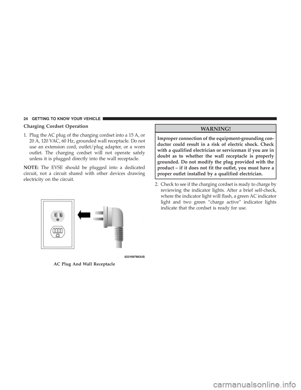
Charging Cordset Operation
1. Plug the AC plug of the charging cordset into a 15 A, or20 A, 120 VAC, 60 Hz, grounded wall receptacle. Do not
use an extension cord, outlet/plug adapter, or a worn
outlet. The charging cordset will not operate safely
unless it is plugged directly into the wall receptacle.
NOTE: The EVSE should be plugged into a dedicated
circuit, not a circuit shared with other devices drawing
electricity on the circuit.
WARNING!
Improper connection of the equipment-grounding con-
ductor could result in a risk of electric shock. Check
with a qualified electrician or serviceman if you are in
doubt as to whether the wall receptacle is properly
grounded. Do not modify the plug provided with the
product – if it does not fit the outlet, you must have a
proper outlet installed by a qualified electrician.
2. Check to see if the charging cordset is ready to charge by reviewing the indicator lights. After a brief self-check,
where the indicator light will flash, a green AC indicator
light and two green “charge active” indicator lights
indicate that the cordset is ready for use.
AC Plug And Wall Receptacle
24 GETTING TO KNOW YOUR VEHICLE
Page 27 of 614
3. If the charging cordset is ready to charge, ensure thevehicle is in PARK, and then connect the charge connec-
tor to the vehicle’s charge inlet. You will hear a “click”
when the charge connector is inserted correctly and
coupled with the vehicle’s charge inlet. 4. When the vehicle commences charging, the Charge
Active Indicator Lights will cycle from left to right, and
then both turn off. This pattern will repeat while the
vehicle is charging. The lights are illuminated at the rate
of approximately one cycle per second.
Cordset Indicator Lights
1 — AC Power Indicator Light
2 — Fault Indicator Light3 — Charge Active Indicator
Lights
Inserting The Charge Connector
Into The Vehicle Charge Inlet
3
GETTING TO KNOW YOUR VEHICLE 25
Page 29 of 614

NOTE:It is good practice to keep the ignition in the OFF
position while conducting Level 1 Charging. This mini-
mizes any additional vehicle loads the EVSE has to sup-
port. The additional electrical loads will extent the High
Voltage Battery charging time.
Troubleshooting Using The Status Indicator Display
If the vehicle is not charging properly, consult the status
indicator lights.
The AC Power Indicator displays the status and safety of
the input power. If this indicator is green, the power is
within acceptable limits to charge the vehicle. If only the
AC Power Indicator is flashing red, then there is a problem
with the AC power at the electrical outlet. If the AC Power
Indicator does not return to green, then the outlet should
be inspected by a licensed electrician to ensure the voltage,
frequency, and grounding are complaint to national and
local electrical codes and ordinances. It may be possible to
attempt charging from a different outlet.
The Fault Indicator displays the status of the Portable
EVSE Cordset and the vehicle connection. The Portable
EVSE Cordset will not allow charging while the fault
indicator is red. If it is off, the Portable EVSE Cordset has
not detected any internal faults, or faults with the vehicle
connection. If the Fault Indicator is flashing red, there is a fault detected either with the Portable EVSE Cordset,
electronics, or with the vehicle connection. The Portable
EVSE Cordset may attempt to retry to provide current to
the vehicle if the fault is cleared. If the Portable EVSE
Cordset does not attempt to provide charge to the vehicle,
the charge connector will need to be removed from the
vehicle to clear the fault.
The fault code list in the table below provides a reference
for the important faults that are detected by the Portable
EVSE Cordset. When a fault is detected, the AC Power
Indicator, the Fault Indicator, or both the AC Power and
Fault Indicators will flash red. If only the AC Power
Indicator is red, there is a problem on the AC Power side of
the unit. If only the Fault Indicator is flashing red, there is
a problem internal to the unit or with the vehicle. If both
the AC Power and Fault Indicators are flashing red, an over
temperature condition is detected at either the AC plug or
within the EVSE enclosure. Additional information about
the faults is provided by a fault code that is displayed on
the two green Charge Rate Indicators. The fault code
consists of four digits, each with a value of 1 or 2. The value
of a digit is the number of indicators illuminated for that
part of the sequence. For example, fault code (1, 2, 1, 1) will
display the following sequence: One indicator will illumi-
nate for 0.3 seconds, then two indicators will illuminate,
3
GETTING TO KNOW YOUR VEHICLE 27
Page 35 of 614

•Charging times may be longer if a thermal self-protection
reduces the charging current from the EVSE.
• If the vehicle’s ignition is in either the ACC or RUN
position, the vehicle charge indicator may not indicate
greater than a 99% state of charge, and will continue to
charge the vehicle, due to the vehicle loads.
Type of EVSE Estimated Charge Time
Level 1 (120V/15A) Approximately 14 hours
Level 2 (240V/30A) Approximately 2 hours
Vehicle Charge Indicators
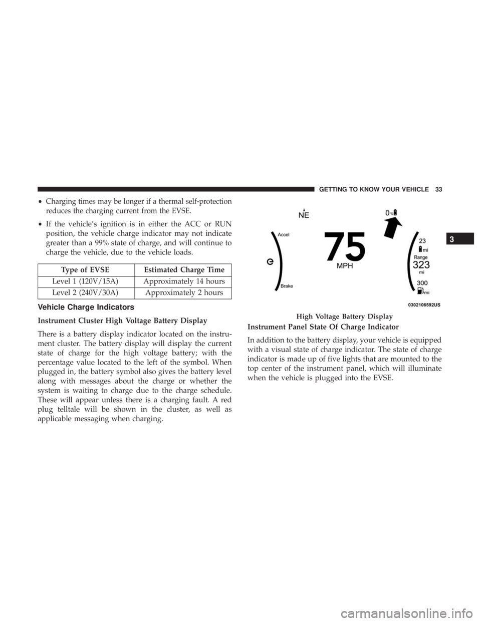
Instrument Cluster High Voltage Battery Display
There is a battery display indicator located on the instru-
ment cluster. The battery display will display the current
state of charge for the high voltage battery; with the
percentage value located to the left of the symbol. When
plugged in, the battery symbol also gives the battery level
along with messages about the charge or whether the
system is waiting to charge due to the charge schedule.
These will appear unless there is a charging fault. A red
plug telltale will be shown in the cluster, as well as
applicable messaging when charging. Instrument Panel State Of Charge Indicator
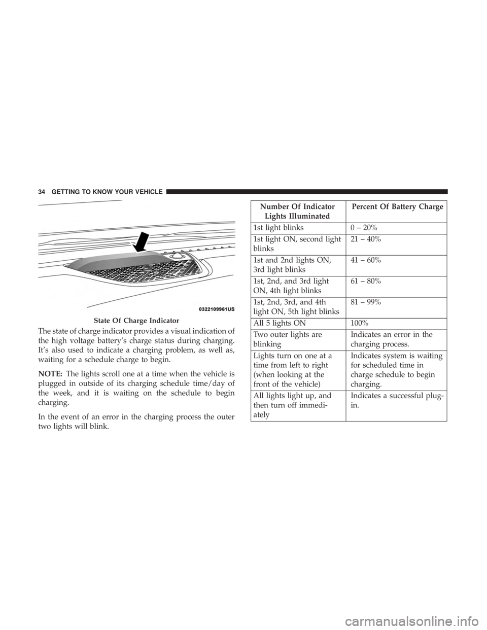
In addition to the battery display, your vehicle is equipped
with a visual state of charge indicator. The state of charge
indicator is made up of five lights that are mounted to the
top center of the instrument panel, which will illuminate
when the vehicle is plugged into the EVSE.High Voltage Battery Display
3
GETTING TO KNOW YOUR VEHICLE 33
Page 36 of 614

The state of charge indicator provides a visual indication of
the high voltage battery’s charge status during charging.
It’s also used to indicate a charging problem, as well as,
waiting for a schedule charge to begin.
NOTE:The lights scroll one at a time when the vehicle is
plugged in outside of its charging schedule time/day of
the week, and it is waiting on the schedule to begin
charging.
In the event of an error in the charging process the outer
two lights will blink.
Number Of Indicator Lights Illuminated Percent Of Battery Charge
1st light blinks 0 – 20%
1st light ON, second light
blinks 21 – 40%
1st and 2nd lights ON,
3rd light blinks 41 – 60%
1st, 2nd, and 3rd light
ON, 4th light blinks 61 – 80%
1st, 2nd, 3rd, and 4th
light ON, 5th light blinks 81 – 99%
All 5 lights ON 100%
Two outer lights are
blinking Indicates an error in the
charging process.
Lights turn on one at a
time from left to right
(when looking at the
front of the vehicle) Indicates system is waiting
for scheduled time in
charge schedule to begin
charging.
All lights light up, and
then turn off immedi-
ately Indicates a successful plug-
in.
State Of Charge Indicator
34 GETTING TO KNOW YOUR VEHICLE
Page 42 of 614
To Unlock The Doors
NOTE:Uconnect Settings lets you program the system to
unlock either the driver’s side doors on the first push (default)
or unlock all doors on the first push of the unlock button on
the key fob. To change the default setting, refer to “Uconnect
Settings” in “Multimedia” for further information.
1st Push Of Key Fob Unlocks
Push and release the unlock button on the key fob once to
unlock the driver front door and sliding door or twice
within five seconds to unlock all doors and liftgate. The
hazard lights will flash to acknowledge the unlock signal.
The illuminated entry system will be activated.
Six Button Key Fob
Seven Button Key FobFirst Push Unlock
40 GETTING TO KNOW YOUR VEHICLE