2018 Alfa Romeo Stelvio warning
[x] Cancel search: warningPage 181 of 276

REAR BACK-UP CAMERA /
DYNAMIC GRIDLINES
Description
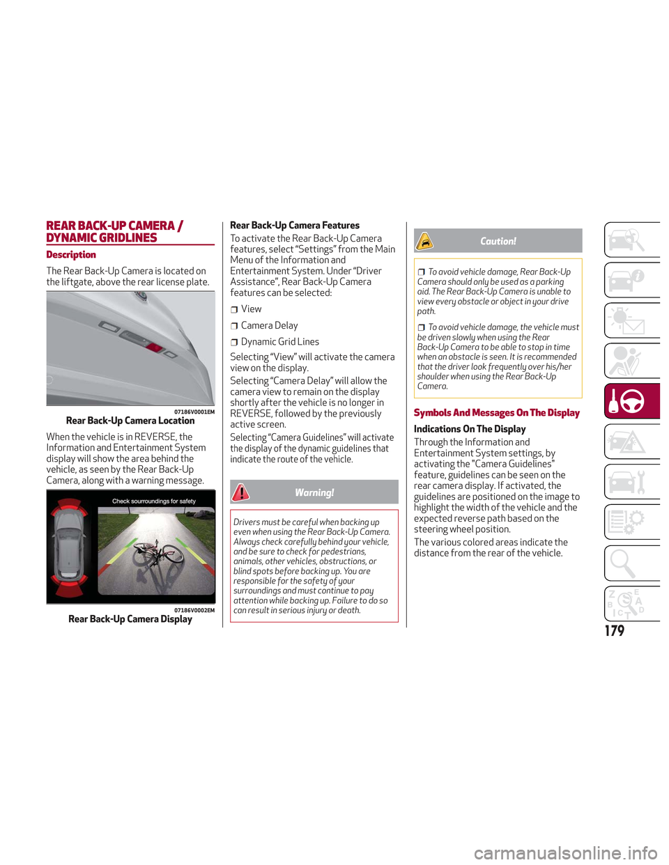
The Rear Back-Up Camera is located on
the liftgate, above the rear license plate.
When the vehicle is in REVERSE, the
Information and Entertainment System
display will show the area behind the
vehicle, as seen by the Rear Back-Up
Camera, along with a warning message.Rear Back-Up Camera Features
To activate the Rear Back-Up Camera
features, select “Settings” from the Main
Menu of the Information and
Entertainment System. Under “Driver
Assistance”, Rear Back-Up Camera
features can be selected:
View
Camera Delay
Dynamic Grid Lines
Selecting “View” will activate the camera
view on the display.
Selecting “Camera Delay” will allow the
camera view to remain on the display
shortly after the vehicle is no longer in
REVERSE, followed by the previously
active screen.
Selecting “Camera Guidelines” will activate
the display of the dynamic guidelines that
indicate the route of the vehicle.
Warning!
Drivers must be careful when backing up
even when using the Rear Back-Up Camera.
Always check carefully behind your vehicle,
and be sure to check for pedestrians,
animals, other vehicles, obstructions, or
blind spots before backing up. You are
responsible for the safety of your
surroundings and must continue to pay
attention while backing up. Failure to do so
can result in serious injury or death.
Caution!
To avoid vehicle damage, Rear Back-Up
Camera should only be used as a parking
aid. The Rear Back-Up Camera is unable to
view every obstacle or object in your drive
path.
To avoid vehicle damage, the vehicle must
be driven slowly when using the Rear
Back-Up Camera to be able to stop in time
when an obstacle is seen. It is recommended
that the driver look frequently over his/her
shoulder when using the Rear Back-Up
Camera.
Symbols And Messages On The Display
Indications On The Display
Through the Information and
Entertainment System settings, by
activating the "Camera Guidelines"
feature, guidelines can be seen on the
rear camera display. If activated, the
guidelines are positioned on the image to
highlight the width of the vehicle and the
expected reverse path based on the
steering wheel position.
The various colored areas indicate the
distance from the rear of the vehicle.
07186V0001EMRear Back-Up Camera Location
07186V0002EMRear Back-Up Camera Display
179
Page 182 of 276

The table below shows the approximate
distances for each area:
AreaDistance From The
Rear Of The Vehicle
Red 0–11.8
inches
(0–30 cm)
Yellow 11.8 inches to 3.3 feet
(30cm–1m)
Green 3.3feetormore(1m
or more)
Messages On The Display
If the liftgate is opened, the camera will
not detect any obstacle behind the
vehicle. The display will show a dedicated
warning message.
Make sure the liftgate is closed by
pushing next to the lock until it clicks.
Important Notes
Ice, snow or mud on the surface of the
camera may reduce its sensitivity. It is
important to keep the camera surface
clean, and free from debris.
When parking, be aware of obstacles
that may be above or below the camera
range.
REFUELING THE VEHICLE
Refueling The Vehicle
Before refueling, make sure that the fuel
type is correct.
Also, stop the engine before refueling.
Note: An inefficient catalytic converter
leads to harmful exhaust emissions, thus
contributing to air pollution.
Caution!
Never introduce leaded fuel to the tank,
even in small amounts in an emergency, as
this would damage the catalytic converter
beyond repair.
Refueling Capacity
To ensure that you fill the tank
completely, top off twice after the first
click of the fuel nozzle.
Further top-off could cause faults in the
fuel feeding system.
Refueling Procedure
The fuel filler door is unlocked when the
central door locking system is unlocked.
It is automatically locked when the
central locking system is applied. Opening The Fuel Filler Door
To refuel proceed as follows:
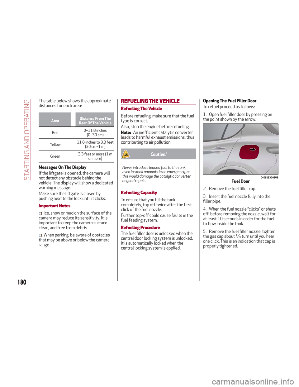
1. Open fuel filler door by pressing on
the point shown by the arrow.
2. Remove the fuel filler cap.
3. Insert the fuel nozzle fully into the
filler pipe.
4. When the fuel nozzle “clicks” or shuts
off, before removing the nozzle, wait for
at least 10 seconds in order for the fuel
to flow inside the tank.
5. Remove the fuel filler nozzle, tighten
the gas cap about ¼ turn until you hear
one click. This is an indication that cap is
properly tightened.
0405133008USFuel Door
180
STARTING AND OPERATING
Page 184 of 276

Warning!
Never have any smoking materials lit in or
near the vehicle when the fuel door is open
or the tank is being filled.
Never add fuel when the engine is running.
This is in violation of most state and federal
fire regulations and may cause the MIL to
turn on.
A fire may result if gasoline is pumped
into a portable container that is inside of a
vehicle. You could be burned. Always place
gas containers on the ground while filling.
Note: If the filler compartment is
washed with a pressure washer, keep it at
a distance of at least 8 inches (20 cm).
VEHICLE LOADING
Certification Label
As required by National Highway Traffic
Safety Administration regulations, your
vehicle has a certification label affixed to
the driver's side door or pillar.
This label contains the month and year of
manufacture, Gross Vehicle Weight
Rating (GVWR), Gross Axle Weight Rating
(GAWR) front and rear, and Vehicle
Identification Number (VIN). A
Month-Day-Hour (MDH) number is
included on this label and indicates the
Month, Day and Hour of manufacture. The
bar code that appears on the bottom of
the label is your VIN.
Gross Vehicle Weight Rating
(GVWR)
The GVWR is the total permissible
weight of your vehicle including driver,
passengers, vehicle, options and cargo.
The label also specifies maximum
capacities of front and rear axle systems
(GAWR). Total load must be limited so
GVWR and front and rear GAWR are not
exceeded.
Payload
The payload of a vehicle is defined as the
allowable load weight a truck can carry,
including the weight of the driver, all
passengers, options and cargo.
Gross Axle Weight Rating (GAWR)
The GAWR is the maximum permissible
load on the front and rear axles. The load
must be distributed in the cargo area so
that the GAWR of each axle is not
exceeded.
Each axle GAWR is determined by the
components in the system with the
lowest load carrying capacity (axle,
springs, tires or wheels). Heavier axles or
suspension components sometimes
specified by purchasers for increased
durability does not necessarily increase
the vehicle's GVWR.
Tire Size
The tire size on the Vehicle Certification
Label represents the actual tire size on
your vehicle. Replacement tires must be
equal to the load capacity of this tire size.
Rim Size
This is the rim size that is appropriate for
the tire size listed.
Inflation Pressure
This is the cold tire inflation pressure for
your vehicle for all loading conditions up
to full GAWR.
182
STARTING AND OPERATING
Page 189 of 276

IN CASE OF EMERGENCY
Have a flat tire or a burnt-out bulb?
At times, a problem such as these may
interfere with your driving experience.
The section on emergencies can help you
to deal with critical situations
independently.
In an emergency, we recommend that you
call the phone number found in the
Warranty Book.
You may also consider contacting an
authorized dealer.HAZARD WARNING LIGHTS.....188
BULB REPLACEMENT .........188
FUSES .................. .193
TIRE SERVICE KIT ............198
JUMP STARTING ............201
ENGINE OVERHEATING ........203
TOWING A DISABLED VEHICLE . . .204
TOW EYES ............... .206
ENHANCED ACCIDENT RESPONSE
SYSTEM (EARS) .............207
EVENT DATA RECORDER (EDR) . . .207
187
Page 190 of 276

HAZARD WARNING LIGHTS
The Hazard Warning flasher switch is
located in the switch bank below the
radio screen.Push the switch once to
turn the hazard warning
flasher on. When the
switch is activated, all
directional turn signals
will flash on and off to
warn oncoming traffic
of an emergency. Push the switch a
second time to turn the hazard warning
flashers off.
This is an emergency warning system and
it should not be used when the vehicle is
in motion. Use it when your vehicle is
disabled and is creating a safety hazard
for other motorists.
When you must leave the vehicle to seek
assistance, the hazard warning flashers
will continue to operate even though the
ignition is cycled to STOP.
Caution!
Prolonged use of the hazard warning
flashers may discharge the vehicle’s battery.
Panic Brake Assist (PBA) System
The PBA system is designed to improve
the vehicle’s braking capacity during
emergency braking.
For further details about the Panic Brake
Assist System, refer to the "Active
Safety Systems" section in the "Safety"
chapter.
BULB REPLACEMENT
General Instructions
Before replacing a bulb, check the
contacts for oxidation.
Replace blown bulbs with others of the
same type and power.
After replacing a headlight bulb,
always check its alignment.
When a light is not working, check that
the corresponding fuse is intact before
changing the bulb. For the location of
fuses, refer to “Fuses” in this chapter.
Note: In some particular climate
conditions, such as low temperature,
humidity, or after washing the vehicle, a
thin condensation layer may form on the
internal surfaces of the front and rear
headlights. This condensation will
disappear after switching on the
headlights.
0403132206USHazard Warning Switch
188
IN CASE OF EMERGENCY
Page 193 of 276

Replacing Exterior Bulbs
Warning!
Only replace bulbs when the engine is off.
Also ensure that the engine is cold, to
prevent the risk of burns.
Front Light Cluster
Direction Indicators
Proceed with the directions below to
change bulbs:
1. Operating inside the engine
compartment, locate the protective
cover.
2. Remove protective cover.3. Turn the bulb/connector assembly
counterclockwise, and then slide it off
the headlight body.
4. Remove the bulb by sliding it off the
bulb holder.
5. Install the new bulb, making sure it is
correctly inserted in the bulb holder.6. Insert the bulb/connector assembly in
the housing on the headlight body and
turn it clockwise, making sure that it is
locked correctly.
7. Install the protective cover.
Front Light Cluster With Main Beam
Xenon Gas Discharge Headlights
To replace the bulbs of the main beam
headlights, contact an authorized dealer.
Caution!
Do not touch the new bulb with your fingers.
Oil contamination will severely shorten bulb
life. If the bulb comes in contact with any oily
surface, clean the bulb with rubbing alcohol.
Replacing Interior Bulbs
Courtesy Mirror Light
To replace the bulbs, proceed as follows:
1. Lift the mirror cover and remove the
lens, using a suitable tool.
08026V0023EMProtective Cover Location
08026V0006EMProtective Cover
08026V0007EMBulb/Connector
191
Page 196 of 276

Fuse Extracting Pliers
To replace a fuse, use the pliers hooked
to the fuse box.
Grab the pliers from the upper tabs,
press them, and extract the pliers pulling
upwards.
The pliers have two different ends, both
of which are specifically designed to
remove the different types of fuses
present in the vehicle:After use, return the pliers to their proper
position by following the below
procedures:
Grasp the pliers from the upper tabs
and insert them into their housing.
Push downward on the pliers into their
housing until they click into place.
Warning!
When replacing a blown fuse, always use
an appropriate replacement fuse with the
same amp rating as the original fuse. Never
replace a fuse with another fuse of higher
amp rating. Never replace a blown fuse with
metal wires or any other material. Do not
place a fuse inside a circuit breaker cavity
or vice versa. Failure to use proper fuses
08036S0001EMBlade Fuses
1 — Electrical Circuit
2 — Blade Fuse With Good Electrical
Circuit
3—
Blade Fuse With Bad Electrical Circuit
08036S0002EMJ-CASE Fuse
1 — Electrical Circuit
2—
Case Fuse With Good Electrical Circuit
3—Case Fuse With Bad Electrical Circuit
08036V0053EMFuse Box
08036S0005EMFuse Extracting Pliers
1 — MINI fuse
2 — J-CASE fuse
194
IN CASE OF EMERGENCY
Page 200 of 276

TIRE SERVICE KIT
Description
If a tire is punctured, you can make a first
emergency repair using the Tire Service
Kit located in the rear storage area under
the load platform.
1. Stop the vehicle in a position where
you can repair the tire safely. You should
be as far as possible from the side of the
road, and in a position that is not
dangerous for oncoming traffic. Turn on
the hazard warning flashers, remove the
safety triangle from the luggage
compartment, and place it at a suitable
distance from the vehicle to make other
drivers aware of your presence.
2. Verify that the valve stem (on the
wheel with the deflated tire) is in a
position that is near to the ground. This
will allow the tire repair kit hoses to reach
the valve stem and keep the tire service
kit flat on the ground.
3. Place the gear selector in PARK (P).
4. Apply the electric park brake and turn
the engine OFF.
To access the Tire Service Kit, open the
liftgate and lift the load floor.The Tire Service Kit consists of:
Sealant cartridge containing the
sealing fluid
Filler Tube
Air compressor, complete with
pressure gauge and connectors
Adhesive label with the writing "Max.
50 mph (80 km/h)”, to be attached in a
position easily visible to the driver (eg. on
the dashboard) after repairing the tire
An instruction pamphlet for reference
in prompt and correct use of the Tire
Service Kit, which must be then given to
the personnel dealing with the
sealant-treated tire
A pair of protective gloves
Some adaptors, for inflating different
elements Note:
The sealing fluid is effective with
external temperatures of between
-40°F (-40°C) and 122°F (50°C).
The sealing fluid has an expiration
date.
0403132214USLoad Floor08066V0002EMTire Service Kit Components
1 — Sealant Cartridge
2 — Filling Hose
3 — Adhesive Label
4 — Air Compressor
198
IN CASE OF EMERGENCY