Page 25 of 114

Instrument and control functions
4-7
4
The electrical circuit of the warning
light can be checked by turning the key
to “ON”. The warning light should
come on for a few seconds, and then
go off.
If the warning light does not come on
initially when the key is turned to “ON”,
or if the warning light remains on, have
a Yamaha dealer check the vehicle.
EAU69891ABS warnin
g li ght “ ”
In normal operation, this warning light
comes on when the key is turned to
“ON”, and goes off after traveling at a
speed of 10 km/h (6 mi/h) or higher.
If the ABS warning light: does not come on when the key is
turned to “ON”
comes on or flashes while riding
does not go off after traveling at a
speed of 10 km/h (6 mi/h) or high-
er
The ABS may not work correctly. If any
of the above occurs, have a Yamaha
dealer check the system as soon as
possible. (See page 4-19 for an expla-
nation of the ABS.)
WARNING
EWA16041
If the ABS warnin g li ght does not go
off after travelin g at a speed of 10
km/h (6 mi/h) or hi gher, or if the
warnin g li ght comes on or flashes
while ri din g, the b rake system re-
verts to conventional brakin g. If ei-
ther of the ab ove occurs, or if the
warnin g li ght does not come on at
all, use extra caution to avoid possi-
b le wheel lock durin g emer gency b
rakin g. Have a Yamaha d ealer
check the brake system an d electri-
cal circuits as soon as possi ble.
EAU77002Traction control system in dicator
li g ht “ ”
This indicator light flashes when trac-
tion control has engaged. If the traction
control system is turned off, the indica-
tor light will come on.
When the vehicle is turned on, the light
will perform a circuit check (come on
for a few seconds and then go off). If
the light does not come on during the
circuit check, or if the light remains on,
Yamaha dealer check the vehicle.
EAU80370Shift li ght
This light can be set to come on and go
off at select engine speeds. (See page
4-15.)
When the vehicle is turned on, the light
will perform a circuit check (come on
for a few seconds and then go off).
If the light does not come on during the
circuit check, have a Yamaha dealer
check the vehicle.
EAU80300Immo bilizer system in dicator li ght
When the key is turned to “OFF” and
30 seconds have passed, the indicator
light will flash steadily to indicate the
immobilizer system is enabled. After 24
hours have passed, the indicator light
will stop flashing, however the immobi-
lizer system is still enabled.
The electrical circuit of the indicator
light can be checked by turning the key
to “ON”. The indicator light should
come on for a few seconds, and then
go off.
ABS
UBN6E0E0.book Page 7 Wednesday, January 25, 2017 1:28 PM
Page 26 of 114

Instrument and control functions
4-8
4 If the indicator light does not come on
initially when the key is turned to “ON”,
if the indicator light remains on, or if the
indicator light flashes in a pattern (if a
problem is detected in the immobilizer
system, the immobilizer system indica-
tor light will flash in a pattern), have a
Yamaha dealer check the vehicle.
TIP
If the immobilizer system indicator light
flashes in the pattern, slowly 5 times
then quickly 2 times, this could be
caused by transponder interference. If
this occurs, try the following.
1. Make sure there are no other im- mobilizer keys close to the main
switch. Other immobilizer system
keys may cause signal interfer-
ence and prevent the engine from
starting.
2. Use the code re-registering key to start the engine.
3. If the engine starts, turn it off, and try starting the engine with the
standard keys.
4. If one or both of the standard keys do not start the engine, take the
vehicle and all 3 keys to a Yamaha
dealer to have the standard keys
re-registered.
EAU3904F
Multi-function meter unit
WARNING
EWA12423
Be sure to stop the vehicle before
makin g any settin g chan ges to the
multi-function meter unit. Chang ing
settin gs while ri din g can d istract the
operator an d increase the risk of an
acci dent.
The multi-function meter unit is
equipped with the following:
speedometer
tachometer
clock
lap timer
coolant temperature display
air intake temperature display
transmission gear display
drive mode display
TCS display
1. Tachometer
2. Shift light
3. TCS display
4. Coolant/air intake temperature display
5. Quick shift icon “QS”
6. Drive mode display
7. Speedometer
8. Multi-function display
9. Clock/lap timer
10.Transmission gear display
11.“RESET” button
12.“SELECT” button
6
5
7
8
9
2
34
101112
1
UBN6E0E0.book Page 8 Wednesday, January 25, 2017 1:28 PM
Page 27 of 114

Instrument and control functions
4-9
4
QS icon
multi-function display
display brightness and shift light
control mode
TIP
To switch the multi-function meter
unit between kilometers and
miles, push the “SELECT” button
for one second.
The “ ” and “GPS” icons require
accessory parts to function.
Speed ometer
The speedometer shows the vehicle’s
traveling speed.
Tachometer
The electric tachometer shows the en-
gine speed, as measured by the rota-
tional velocity of the crankshaft, in
revolutions per minute (r/min). When
the vehicle is first powered on, the ta-
chometer needle will sweep once
across the r/min range and then return
to zero.
NOTICE
ECA10032
Do not operate the en gine in the ta-
chometer red zone. Re
d zone: 16500 r/min an d a bove
Clock an d lap timer
The clock uses a 12-hour time system.
To set the clock
1. Turn the key to “ON”.
2. Push the “SELECT” button and the “RESET” button for two sec-
onds. The hour digits will start
flashing.
3. Push the “RESET” button to set the hours.
4. Push the “SELECT” button, and the minute digits will start flashing.
5. Push the “RESET” button to set the minutes.
6. Push the “SELECT” button to con- firm the settings and start the
clock.
To switch between the clock and lap
timer
Push and release the “SELECT” button
and the “RESET” button at the same
time.
1. Tachometer
2. Tachometer red zone
2
1
1. Clock
1
UBN6E0E0.book Page 9 Wednesday, January 25, 2017 1:28 PM
Page 28 of 114

Instrument and control functions
4-10
4 The lap timer records and stores up to
20 lap times. The lap time history re-
cords are divided into two groups, “L”
for lap order and “F” for fastest order.
For lap order, the most recent lap is
designated L1 (and L19 will become
L20). In the case of fast lap history, any
new fast lap within the top 20 will be in-
serted and the previous F20 will be
pushed out of the history.
To use the lap timer
1. Push the “RESET” button for one
second to set the lap timer to the
counting-ready state (the colon “:”
and period “.” will flash).
2. Push the pass switch “ ” to start the lap timer.
3. Push the pass switch “ ” to mark the start of each new lap.
4. Push the “SELECT” button to stop the lap timer.
5. Push the “SELECT” button again to reset the lap timer (or push the
“RESET” button for one second to
reset the lap timer and set it to the
counting-ready state). To view the lap time history
1. Push the “SELECT” button for one
second. Lap order history is se-
lected (indicated by “L-20” in the
lower part of the display), or push
the “SELECT” button again to se-
lect fast lap history (indicated by
“F-20”). “L-20” = lap order (most re-
cent is L1)
“F-20” = fastest order (fastest
lap time is F1)
2. Push the “RESET” button and the 1st lap time of that history group
(indicated by “L1” or “F1”) is
shown.
3. Use the “SELECT” button to scroll the history in ascending order, or
use the “RESET” button to scroll
the history in descending order.
1. Lap timer
1
1. History type (L-20 or F-20)
1. Lap number/Fastest rank
2. Lap time
1
1
2
UBN6E0E0.book Page 10 Wednesday, January 25, 2017 1:28 PM
Page 29 of 114

Instrument and control functions
4-11
4
4. When you have finished viewing
the lap records you can: push the “RESET” button for
one second to delete that
group of lap records.
push the “SELECT” button
for one second to exit and re-
turn to the lap timer.
Coolant temperature display
This display indicates the temperature
of the coolant from 41 °C to 124 °C in
1 °C increments.
If the coolant temperature is between
117 and 124 °C, the coolant tempera-
ture display flashes and the coolant
temperature warning light comes on. If
this occurs, reduce the load on the en-
gine by riding at a moderate pace, at
low rpm, until the coolant temperature
goes down. If the temperature does
not go down, or if the message “HI”
flashes, stop the engine and let it cool.
(See page 7-42.)
TIP
When the vehicle is turned on, the
coolant temperature display is au-
tomatically selected.
When the coolant temperature is
below 41 °C, “Lo” will be dis-
played.
Air intake temperature display
This display indicates the temperature
of the air drawn into the air intake duct.
Push the “RESET” button to switch the
display between the coolant tempera-
ture and the air intake temperature.
TIP
When the coolant temperature
display is selected, “C” is dis-
played for one second, and then
the coolant temperature is dis-
played.
When the air intake temperature
display is selected, “A” is dis-
played for one second, and then
the air intake temperature is dis-
played.
When the air temperature is below
–9 °C, “–9 °C” will be displayed.
1. Coolant temperature display
1
1. Air intake temperature display
1
UBN6E0E0.book Page 11 Wednesday, January 25, 2017 1:28 PM
Page 30 of 114
Instrument and control functions
4-12
4 Transmission
gear display
This display shows the selected gear.
The neutral position is indicated by “ ”
and by the neutral indicator light.
Drive mo de display
This display indicates which drive
mode has been selected: “STD”, “A” or
“B”. For more details on the modes
and on how to select them, see page
3-1. TCS
display
This display indicates which traction
control system setting has been se-
lected: “1” through “6” or “OFF”. For
more details on the TCS settings and
on how to select them, see page 3-2.
QS icon
When the quick shift system is set to
on (i.e. when the shift switch is con-
nected), this icon will turn on. See page
3-4 for quick shift information.
1. Neutral indicator light “ ”
2. Transmission gear display
1. Drive mode display
2 1
1
1. TCS display
1. Quick shift icon “QS”
1
1
UBN6E0E0.book Page 12 Wednesday, January 25, 2017 1:28 PM
Page 31 of 114

Instrument and control functions
4-13
4
Multi-function
display
The multi-function display is equipped
with the following: odometer
two tripmeters
fuel reserve tripmeter
instantaneous fuel consumption
average fuel consumption
total fuel used
Navi gatin g the multi-function d is-
play
Push the “SELECT” button to change
between the odometer “ODO”, tripme-
ters “TRIP 1” and “TRIP 2”, instanta-
neous fuel consumption “km/L”,
“L/100 km” or “MPG”, average fuel
consumption “AVE _ _ _._ km/L”, “AVE
_ _ _._ L/100 km” or “AVE _ _ _._ MPG”,
and total fuel used “_ _._” in the follow-
ing order:
ODO → TRIP 1 → TRIP 2 → km/L,
L/100 km or MPG → AVE _ _ _._ km/L,
AVE _ _ _._ L/100 km or AVE _ _ _._
MPG → _ _._ → ODO
O dometer an d tripmeters
The odometer shows the total distance
traveled by the vehicle. The tripmeters show the distance trav-
eled since they were last reset. To reset
a tripmeter, push the “RESET” button
for one second.
TIP
The odometer will lock at 999999.
The tripmeters will reset and con-
tinue counting after 9999.9 is
reached.
Fuel reserve tripmeter
If the fuel level warning light comes on,
the display will automatically change to
the fuel reserve tripmeter “TRIP F” and
start counting the distance traveled
from that point. In this case, push the
“SELECT” button to switch the display
in the following order:
TRIP F → km/L, L/100 km or MPG →
AVE _ _ _._ km/L, AVE _ _ _._ L/100 km
or AVE _ _ _._ MPG → _ _._ → ODO →
TRIP 1 → TRIP 2 → TRIP F
TIP
If you do not reset the fuel reserve trip-
meter manually, after refueling and
traveling 5 km (3 mi), it will reset auto-
matically and disappear from the dis-
play.
1. Multi-function display
1
UBN6E0E0.book Page 13 Wednesday, January 25, 2017 1:28 PM
Page 32 of 114

Instrument and control functions
4-14
4 Instantaneous fuel consumption
This function calculates the fuel con-
sumption under current riding condi-
tions.
The instantaneous fuel consumption
display can be set to either “km/L” or
“L/100 km” when using kilometers, or
to “MPG” when using miles. When us-
ing kilometers, push the “SELECT”
button for one second to switch be-
tween “km/L” and “L/100 km”.
“km/L”: The distance that can be
traveled on 1.0 L of fuel under the
current riding conditions is shown.
“L/100 km”: The amount of fuel
necessary to travel 100 km under
the current riding conditions is
shown.
“MPG”: The distance that can be
traveled on 1.0 US gal of fuel un-
der the current riding conditions is
shown.
TIP
If traveling at speeds under 20 km/h
(12 mi/h), “_ _ _._” is displayed.
Avera ge fuel consumption
This function calculates the average
fuel consumption since it was last re-
set.
The average fuel consumption display
can be set to either “AVE _ _ _._ km/L”
or “AVE _ _ _._ L/100 km” when using
kilometers, or to “AVE _ _ _._ MPG”
when using miles. When using kilome-
ters, push the “SELECT” button for one
second to switch between “AVE _ _ _._
km/L” and “AVE _ _ _._ L/100 km”. “AVE _ _ _._ km/L”: The average
distance that can be traveled on
1.0 L of fuel is shown.
“AVE _ _ _._ L/100 km”: The aver-
age amount of fuel necessary to
travel 100 km is shown.
“AVE _ _ _._ MPG”: The average
distance that can be traveled on
1.0 US gal of fuel is shown.
TIP
To reset the average fuel con-
sumption display, push the “RE-
SET” button for one second.
After resetting the average fuel
consumption display, “_ _ _._” will
be shown until the vehicle has
traveled 1 km (0.6 mi).
1. Instantaneous fuel consumption display
1
1. Average fuel consumption display
1
UBN6E0E0.book Page 14 Wednesday, January 25, 2017 1:28 PM
 1
1 2
2 3
3 4
4 5
5 6
6 7
7 8
8 9
9 10
10 11
11 12
12 13
13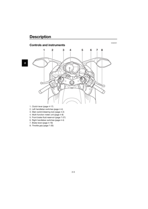 14
14 15
15 16
16 17
17 18
18 19
19 20
20 21
21 22
22 23
23 24
24 25
25 26
26 27
27 28
28 29
29 30
30 31
31 32
32 33
33 34
34 35
35 36
36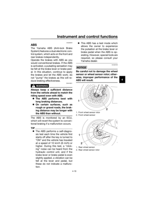 37
37 38
38 39
39 40
40 41
41 42
42 43
43 44
44 45
45 46
46 47
47 48
48 49
49 50
50 51
51 52
52 53
53 54
54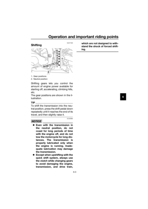 55
55 56
56 57
57 58
58 59
59 60
60 61
61 62
62 63
63 64
64 65
65 66
66 67
67 68
68 69
69 70
70 71
71 72
72 73
73 74
74 75
75 76
76 77
77 78
78 79
79 80
80 81
81 82
82 83
83 84
84 85
85 86
86 87
87 88
88 89
89 90
90 91
91 92
92 93
93 94
94 95
95 96
96 97
97 98
98 99
99 100
100 101
101 102
102 103
103 104
104 105
105 106
106 107
107 108
108 109
109 110
110 111
111 112
112 113
113