Page 65 of 114
Periodic maintenance an d a djustment
7-8
7
3. Slide the cowling as shown.
4. Remove the upper projections
from the slots, and then slide the
cowling forward. To install the cowling
1. Slide the cowling rearward, and
then fit the upper projections into
the slots.
2. Slide the cowling as shown.
3. Install the bolts, quick fasteners, and quick fastener screw.
1. Bolt
1. Quick fastener
1. Cowling A
1
1
1
1. Cowling A
1. Cowling A
1. Cowling A
1
1
1
UBN6E0E0.book Page 8 Wednesday, January 25, 2017 1:28 PM
Page 66 of 114
Periodic maintenance an d a djustment
7-9
7
TIP
Install the bolts loosely, then install the
quick fasteners and quick fastener
screw, and then tighten the bolts.
4. Install the panel.
Cowlin g B
To remove the cowling
1. Remove panel A and cowling A. (See page 7-11.)
2. Remove cowling B by removing the bolts.
To install the cowling
1. Place cowling B in its original po- sition, and then install the bolts.
2. Install cowling A and panel A.
Cowlin g C
To remove the cowling
1. Remove panel B. (See page 7-11.)
2. Remove the bolts, quick fastener, and quick fastener screw. 3. Slide the cowling as shown.
1. Cowling B
2. Bolt
1
2 2
1. Cowling C
2. Bolt
3. Quick fastener screw
1. Bolt
1. Quick fastener
1
2
2
3
1
1
UBN6E0E0.book Page 9 Wednesday, January 25, 2017 1:28 PM
Page 67 of 114
Periodic maintenance an d a djustment
7-10
7
4. Remove the cowling by removing
the upper projections from the
slots.
To install the cowling
1. Fit the upper projections into the slots.
2. Slide the cowling as shown. 3. Install the bolts, quick fastener,
and quick fastener screw.
TIP
Install the bolts loosely, then install the
quick fastener and quick fastener
screw, and then tighten the bolts.
4. Install the panel.
Cowlin g D
To remove the cowling
1. Remove panel B and cowling C. (See page 7-11.)
2. Remove cowling D by removing the bolts.
To install the cowling
1. Place cowling D in its original po- sition, and then install the bolts.
1. Cowling C
1. Cowling C
1. Cowling C
1
1
1
1. Cowling C
1. Cowling D
2. Bolt
1
2
12
UBN6E0E0.book Page 10 Wednesday, January 25, 2017 1:28 PM
Page 68 of 114

Periodic maintenance an d a djustment
7-11
7 2. Install cowling C and panel B.
EAU79970Panels A an
d B
To remove a panel
Remove the quick fasteners, and then
pull the panel off as shown.
To install a panel
Place the panel in the original position,
and then install the quick fasteners.
EAU19653
Checkin g the spark plu gs
The spark plugs are important engine
components, which should be
checked periodically, preferably by a
Yamaha dealer. Since heat and depos- its will cause any spark plug to slowly
erode, they should be removed and
checked in accordance with the peri-
odic maintenance and lubrication
chart. In addition, the condition of the
spark plugs can reveal the condition of
the engine.
The porcelain insulator around the
center electrode of each spark plug
should be a medium-to-light tan (the
ideal color when the vehicle is ridden
normally), and all spark plugs installed
in the engine should have the same
color. If any spark plug shows a dis-
tinctly different color, the engine could
be operating improperly. Do not at-
tempt to diagnose such problems
yourself. Instead, have a Yamaha deal-
er check the vehicle.
If a spark plug shows signs of elec-
trode erosion and excessive carbon or
other deposits, it should be replaced.
Before installing a spark plug, the
spark plug gap should be measured
with a wire thickness gauge and, if
necessary, adjusted to specification.
1. Panel A
2. Quick fastener
2
1
Specified spark plu g:
NGK/CR10EK
UBN6E0E0.book Page 11 Wednesday, January 25, 2017 1:28 PM
Page 69 of 114

Periodic maintenance an d a djustment
7-12
7
Clean the surface of the spark plug
gasket and its mating surface, and
then wipe off any grime from the spark
plug threads.
TIP
If a torque wrench is not available
when installing a spark plug, a good
estimate of the correct torque is 1/4–
1/2 turn past finger tight. However, the
spark plug should be tightened to the
specified torque as soon as possible.
NOTICE
ECA10841
Do not use any tools to remove or in-
stall the spark plu
g cap, otherwise
the i gnition coil coupler may get
d ama ged . The spark plu g cap may
b e difficult to remove b ecause the
ru bber seal on the en d of the cap fits
ti g htly. To remove the spark plu g
cap, simply twist it b ack and forth
while pullin g it out; to install it, twist
it back an d forth while pushin g it in.
EAU36112
Canister
This model is equipped with a canister
to prevent the discharging of fuel vapor
into the atmosphere. Before operating
this vehicle, make sure to check the
following:
Check each hose connection.
Check each hose and canister for
cracks or damage. Replace if
damaged.
Make sure that the canister
breather is not blocked, and if
necessary, clean it.
1. Spark plug gap
Spark plu g g ap:
0.6–0.7 mm (0.024–0.028 in)
Ti ghtening torque:
Spark plug: 13 N·m (1.3 kgf·m, 9.4 lb·ft)
11
1. Canister
2. Canister breather
2
1
UBN6E0E0.book Page 12 Wednesday, January 25, 2017 1:28 PM
Page 70 of 114

Periodic maintenance an d a djustment
7-13
7
EAU80312
En gine oil an d oil filter car-
tri dg e
The engine oil level should be checked
before each ride. In addition, the oil
must be changed and the oil filter car-
tridge replaced at the intervals speci-
fied in the periodic maintenance and
lubrication chart.
To check the en gine oil level
1. Place the vehicle on a level surfa- ce and hold it in an upright posi-
tion. A slight tilt to the side can
result in a false reading.
2. Start the engine, warm it up for several minutes, and then turn it
off.
3. Wait a few minutes until the oil set- tles.
4. Remove the engine oil dipstick and wipe it clean, insert it back
into the hole (without screwing it
in), and then remove it again to
check the oil level.
TIP
The engine oil should be between the
minimum and maximum level marks.
5. Check the dipstick O-ring fordamage, and replace it if neces-
sary.
6. If the engine oil is at or below the minimum level mark, remove the
engine oil filler cap, and then add
sufficient oil of the recommended
type to raise it to the correct level.
7. Check the filler cap O-ring for damage, and replace it if neces-
sary.
8. Insert and tighten the engine oil dipstick, and then install and tight-
en the oil filler cap.
To chan ge the en gine oil (with or
without oil filter cartridge replace-
ment) 1. Place the vehicle on a level surfa- ce.
2. Remove cowlings A and B. (See page 7-7.)
3. Start the engine, warm it up for several minutes, and then turn it
off.
4. Place an oil pan under the engine to collect the used oil.
1. Engine oil dipstick
2. O-ring
3. Maximum level mark
4. Minimum level mark
1
2
3
4
1. Engine oil filler cap
2. O-ring
1
2
1
UBN6E0E0.book Page 13 Wednesday, January 25, 2017 1:28 PM
Page 71 of 114
Periodic maintenance an d a djustment
7-14
7
5. Remove the engine oil filler cap,
the engine oil drain bolt and its
gasket to drain the oil from the
crankcase.
TIP
Skip steps 6–12 if the oil filter cartridge
is not being replaced.
6. Remove the shift arm bolt, andthen pull the shift arm off the shift
shaft.
TIP
If necessary, disconnect the shift
switch and connecting rod by loosen-
ing the bottom nut.
7. Remove the fuel tank overflowhose from the guides.
8. Remove the oil filter cartridge with an oil filter wrench.
TIP
An oil filter wrench is available at a
Yamaha dealer.
9. Apply a thin coat of clean engine oil to the O-ring of the new oil filter
cartridge.
1. Engine oil drain bolt
2. Gasket
1. Shift arm
2. Shift arm bolt
3. Oil filter cartridge
4. Guide
5. Fuel tank overflow hose
1
2
3
4
5
2
1
1. Shift switch
2. Connecting rod
3. Nut
1. Oil filter wrench
1
3
2
1
UBN6E0E0.book Page 14 Wednesday, January 25, 2017 1:28 PM
Page 72 of 114

Periodic maintenance an d a djustment
7-15
7
TIP
Make sure that the O-ring is properly
seated.
10. Install the new oil filter cartridge
with an oil filter wrench, and then
tighten it to the specified torque
with a torque wrench.
11. Install the fuel tank overflow hose into the guides, then place them in
their original position.
12. Install the shift arm by aligning the slot in the shift arm with the mark
on the shift shaft and installing the
shift arm bolt, then tightening it to
the specified torque. NOTICE: Be
sure to ali gn the slot an d mark to ensure proper shiftin
g. If the
slot an d mark are not ali gne d,
the shift arm will not move cor-
rectly an d you may not be ab le
to shift up or down.
[ECA24140]
13. Install the engine oil drain bolt and
its new gasket, and then tighten
the bolt to the specified torque.
14. Refill with the specified amount of the recommended engine oil.
1. O-ring
1. Torque wrench
Tightenin g torque:
Oil filter cartridge: 17 N·m (1.7 kgf·m, 12 lb·ft)
1
1. Shift arm
2. Shift arm bolt
3. Slot
4. Shift shaft
5. Mark
Tightening torque:
Shift arm bolt: 10 N·m (1.0 kgf·m, 7.2 lb·ft)
Ti ghtening torque:
Engine oil drain bolt: 43 N·m (4.3 kgf·m, 31 lb·ft)
Recommen ded en gine oil:
See page 9-1.
Oil quantity: Oil change:2.40 L (2.54 US qt, 2.11 Imp.qt)
With oil filter removal: 2.60 L (2.75 US qt, 2.29 Imp.qt)
2
1
3
4
5
UBN6E0E0.book Page 15 Wednesday, January 25, 2017 1:28 PM
 1
1 2
2 3
3 4
4 5
5 6
6 7
7 8
8 9
9 10
10 11
11 12
12 13
13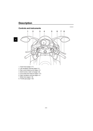 14
14 15
15 16
16 17
17 18
18 19
19 20
20 21
21 22
22 23
23 24
24 25
25 26
26 27
27 28
28 29
29 30
30 31
31 32
32 33
33 34
34 35
35 36
36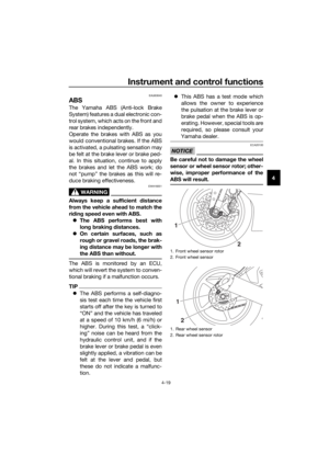 37
37 38
38 39
39 40
40 41
41 42
42 43
43 44
44 45
45 46
46 47
47 48
48 49
49 50
50 51
51 52
52 53
53 54
54 55
55 56
56 57
57 58
58 59
59 60
60 61
61 62
62 63
63 64
64 65
65 66
66 67
67 68
68 69
69 70
70 71
71 72
72 73
73 74
74 75
75 76
76 77
77 78
78 79
79 80
80 81
81 82
82 83
83 84
84 85
85 86
86 87
87 88
88 89
89 90
90 91
91 92
92 93
93 94
94 95
95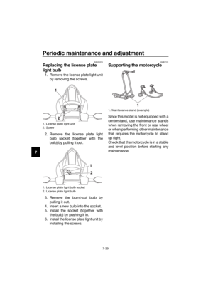 96
96 97
97 98
98 99
99 100
100 101
101 102
102 103
103 104
104 105
105 106
106 107
107 108
108 109
109 110
110 111
111 112
112 113
113


