Page 81 of 208
4-43
4
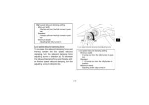
Low speed rebound damping forceTo increase the rebound damping force and
thereby harden the low speed rebound
damping, turn the rebound damping force
adjusting screw in direction (a). To decrease
the rebound damping force and thereby soft-
en the low speed rebound damping, turn the
adjusting screw in direction (b).High speed rebound damping settingMinimum (soft):4 turn(s) out from the fully turned in posi-
tion
Standard: 2 turn(s) out from the fully turned in posi-
tion
Maximum (hard): Adjusting bolt fully turned in
1. Low speed rebound damping force adjusting screwLow speed rebound damping setting Minimum (soft):4 turn(s) out from the fully turned in posi-
tion
Standard: 1 1/2 turn(s) out from the fully turned in
position
Maximum (hard): Adjusting screw fully turned in
1
(a)
(b)
U2HC7ME0.book Page 43 Tuesday, April 19, 2016 10:33 AM
Page 82 of 208
4-44
4
Compression damping force
High speed compression damping forceTo increase the compression damping force
and thereby harden the high speed compres-
sion damping, turn the compression damping
force adjusting bolt in direction (a). To de-
crease the compression damping force and
thereby soften the high speed compression
damping, turn the adjusting bolt in direction
(b).
YXZ10YMXHYXZ10YMSH1. High speed compression damping force adjusting bolt
1
(a)
(b)
1. High speed compression damping force adjusting boltHigh speed compression damping setting
Minimum (soft):4 turn(s) out from the fully turned in posi-
tion
Standard: 1 1/2 (YXZ10YMXH)
2 (YXZ10YMSH) turn(s) out from the fully
turned in position
Maximum (hard): Adjusting bolt fully turned in
1
(a)
(b)
U2HC7ME0.book Page 44 Tuesday, April 19, 2016 10:33 AM
Page 83 of 208
4-45
4
Low speed compression damping forceTo increase the compression damping force
and thereby harden the low speed compres-
sion damping, turn the compression damping
force adjusting screw in direction (a). To de-
crease the compression damping force and
thereby soften the low speed compression
damping, turn the adjusting screw in direction
(b).
YXZ10YMXHYXZ10YMSH1. Low speed compression damping force adjusting screw
1
(a)
(b)
1. Low speed compression damping force adjusting screwLow speed compression damping setting
Minimum (soft):4 turn(s) out from the fully turned in posi-
tion
Standard: 1 1/2 (YXZ10YMXH)
2 (YXZ10YMSH) turn(s) out from the fully
turned in position
Maximum (hard): Adjusting screw fully turned in
1
(a)
(b)
U2HC7ME0.book Page 45 Tuesday, April 19, 2016 10:33 AM
Page 84 of 208

4-46
4
WARNING
EWB03500These shock absorber assemblies contain
highly pressurized nitrogen gas. Read and
understand the following information be-
fore handling the shock absorber assem-
blies.
Do not tamper with or attempt to open
the cylinder assemblies.
Do not subject the shock absorber as-
sembly to an open flame or other high
heat source. This may cause the unit to
explode due to excessive gas pressure.
Do not deform or damage the cylinders
in any way. Cylinder damage will result in
poor damping performance.
Do not dispose of a damaged or worn
out shock absorber assembly yourself.
Take the shock absorber assembly to a
Yamaha dealer for any service.
EBU35052Auxiliary DC jackThe auxiliary DC jack is located at the left side
of the glove compartment. The auxiliary DC
jack can be used for suitable work lights, ra-
dios, etc. The auxiliary DC jack should only be
used when the engine is running and the
lights are turned off.NOTICEECB02250 Do not use accessories requiring more
than the stated maximum capacity. Do-
ing so may overload the circuit and cau-
se the fuse to blow.
If accessories are used without the en-
gine running, the battery may discharge.
Do not use an automotive cigarette light-
er or other accessories with a plug that
gets hot, because the jack can be dam-
aged. 1. Set the light switch to “ ” (off).
2. Turn the accessory off.
3. Start the engine. (See page 6-2.)
U2HC7ME0.book Page 46 Tuesday, April 19, 2016 10:33 AM
Page 85 of 208
4-47
4
4. Open the auxiliary DC jack cap, and theninsert the accessory power plug into the
jack.
5. Turn the accessory on.
6. When the auxiliary DC jack is not being used, cover it with the cap.1. Auxiliary DC jack cap
2. Auxiliary DC jackMaximum rated capacity for the auxiliary DC
jack:DC 12 V, 10 A (120 W)
2
1
U2HC7ME0.book Page 47 Tuesday, April 19, 2016 10:33 AM
Page 86 of 208

5-1
5
EBU31574
FOR YOUR SAFETY – PRE-OPERATION CHECKS
EBU31583Inspect your vehicle each time you use it to make sure the vehicle is in safe operating condition.
Always follow the inspection and maintenance procedures and schedules described in the Own-
er’s Manual.
WARNING
EWB00482Failure to inspect or maintain the vehicle properly increases the possibility of an accident
or equipment damage. Do not operate the vehicle if you find any problem. If a problem can-
not be corrected by the procedures provided in this manual, have the vehicle inspected by
a Yamaha dealer. Before using this vehicle, check the following points:
ITEM ROUTINE PAGE
Brakes • Check operation, free play, fluid level, and fluid leakage.
• Fill with DOT 4 brake fluid if necessary. 5-3, 8-44, 8-50
Clutch • Check operation, free play, fluid level, and fluid leakage.
• Fill with DOT 4 brake fluid if necessary. 5-3, 8-47
Parking brake • Check for proper operation, condition, and free play. 8-49
Fuel • Check fuel level.
• Fill with the recommended fuel if necessary. 5-4
U2HC7ME0.book Page 1 Tuesday, April 19, 2016 10:33 AM
Page 87 of 208
5-2
5
Engine oil• Check oil level.
• Fill with oil to proper level if necessary.
5-5, 8-15
Drivetrain • Check front differential, transmission case, and rear final
gear for leakage. 5-6, 5-6, 5-7, 8-26,
8-29, 8-31
Coolant • Check coolant level in reservoir.
• Fill with coolant if necessary. 5-6, 8-33
Accelerator pedal • Check free play and for proper operation. 5-7
Seat belts • Check for proper operation and belt wear. 5-7
Passenger handhold • Check for stability and proper fastening. 5-7, 7-8
Steering • Check for proper operation. 5-7
Shift lever • Check for proper operation. 5-8
Fittings and fasteners • Check all fittings and fasteners. 5-8
Instruments, lights and
switches • Check operation, and correct if necessary.
5-8, 8-63, 8-64
Wheels and tires • Check tire pressure and for wear and damage. 5-8, 8-54, 8-56
Axle boots • Check for damage. 8-35
ITEM
ROUTINE PAGE
U2HC7ME0.book Page 2 Tuesday, April 19, 2016 10:33 AM
Page 88 of 208

5-3
5
EBU31731Front and rear brakesBrake pedal
Check that there is no free play in the brake
pedal. If there is free play, have a Yamaha
dealer check the brake system. (See page
8-48.)
Check the operation of the brake pedal. It
should move smoothly and there should be
a firm feeling when the brakes are applied.
If not, have the vehicle inspected by a
Yamaha dealer.
Brake fluid level
Check the brake fluid level. Add fluid if neces-
sary. (See page 8-45.) Brake fluid leakage
Check to see if any brake fluid is leaking out
of the pipe joints or the brake fluid reservoir.
Apply the brakes firmly for one minute. If there
is any leakage, have the vehicle inspected by
a Yamaha dealer.
Brake operation
Check the operation of the brakes at the start
of every drive. Test the brakes at slow speed
after starting out to make sure they are work-
ing properly. If the brakes do not provide
proper braking performance, inspect the
brake system. (See page 8-44.)
EBU35491ClutchClutch pedal
Check the operation of the clutch pedal. The
pedal should move smoothly and there
should be some resistance when the clutch
pedal is depressed.
Specified brake fluid: DOT 4
U2HC7ME0.book Page 3 Tuesday, April 19, 2016 10:33 AM