Page 17 of 88

Instrument and control functions
3-2
3
Keep other immo bilizer system
keys away from the main switch
as they may cause si gnal inter-
ference.
EAU57670
Main switchThe main switch controls the ignition
and lighting systems. The various main
switch positions are described below.NOTICE
ECA17961
Do not use metal key chains or keep
more than one key on the same key
rin g. While the vehicle is in motion, a
metal key chain, metallic key rin gs,
or a dditional keys coul d contact sur-
roun din g components an d scratch
them. Therefore, it is recommen ded
to use a cloth or leather key chain.
TIPBe sure to use the standard key (black
bow) for regular use of the vehicle. To
minimize the risk of losing the code re-
registering key (red bow), keep it in a
safe place and only use it for code re-
registering.
EAU38531
ON
All electrical circuits are supplied with
power; the meter lighting, taillight, li-
cense plate light and auxiliary light
come on, and the engine can be start-
ed. The key cannot be removed.TIPThe headlight comes on automatically
when the engine is started and stays
on until the key is turned to “OFF”,
even if the engine stalls.
EAU45752
OFF
All electrical systems are off. The key
can be removed.
P
ON
OFF
UBS5E0E0.book Page 2 Wednesday, October 19, 2016 10:21 AM
Page 18 of 88

Instrument and control functions
3-3
3
WARNING
EWA10073
Never turn the key to “OFF” while
the vehicle is movin g, otherwise the
electrical systems will be switched
off, which may result in loss of con-
trol or an acci dent.
EAU62271
(Parkin g)
The hazard lights and turn signal lights
can be turned on, but all other electri-
cal systems are off. The key can be re-
moved.
The key must be pushed in from the
“OFF” position to be turned to “ ”.
NOTICE
ECA20760
Usin g the hazar d or turn si gnal li ghts
for an exten ded len gth of time may
cause the battery to d ischarge.
EAU4939C
In dicator li ghts an d warnin g
li g hts
EAU11022
Turn si gnal in dicator li ght “ ”
This indicator light flashes when a turn
signal light is flashing.
EAU11061
Neutral in dicator li ght “ ”
This indicator light comes on when the
transmission is in the neutral position.
EAU11081
Hi gh beam in dicator li ght “ ”
This indicator light comes on when the
high beam of the headlight is switched
on.
EAU11256
Oil level warnin g li ght “ ”
This warning light comes on if the en-
gine oil level is low.
The electrical circuit of the warning
light can be checked by turning the key
to “ON”. The warning light should
come on for a few seconds and then
go off.
If the warning light does not come on
initially when the key is turned to “ON”,
or if the warning light remains on after
confirming that the oil level is correct
(see page 6-11), have a Yamaha dealer
check the vehicle.
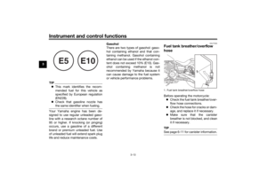
1. Oil level warning light “ ”
2. Immobilizer system indicator light “ ”
3. Turn signal indicator light “ ”
4. Anti-lock Brake System (ABS) warning light “ ”
5. Fuel level warning light “ ”
6. Engine trouble warning light “ ”
7. Neutral indicator light “ ”
8. High beam indicator light “ ”
1
35 42
8
7
6
ABS
UBS5E0E0.book Page 3 Wednesday, October 19, 2016 10:21 AM
Page 19 of 88

Instrument and control functions
3-4
3
TIP Even if the oil level is sufficient, the
warning light may flicker when rid-
ing on a slope or during sudden
acceleration or deceleration, but
this is not a malfunction.
This model is equipped with a self-
diagnosis device for the oil level
detection circuit. If a problem is
detected in the oil level detection
circuit, the oil level warning light
will flash repeatedly. If this occurs,
have a Yamaha dealer check the
vehicle.
EAU11368
Fuel level warnin g li ght “ ”
This warning light comes on when the
fuel level drops below approximately
2.8 L (0.74 US gal, 0.62 Imp.gal). When
this occurs, refuel as soon as possible.
The electrical circuit of the warning
light can be checked by turning the key
to “ON”. The warning light should
come on for a few seconds and then
go off. If the warning light does not come on
initially when the key is turned to “ON”,
or if the warning light remains on after
refueling, have a Yamaha dealer check
the vehicle.
TIPThis model is equipped with a self-di-
agnosis device for the fuel level detec-
tion circuit. If a problem is detected in
the fuel level detection circuit, the fuel
level warning light will flash repeatedly.
If this occurs, have a Yamaha dealer
check the vehicle.
EAU73171
En
gine trou ble warnin g li ght “ ”
This warning light comes on if a prob-
lem is detected in the engine or other
vehicle control system. If this occurs,
have a Yamaha dealer check the on-
board diagnostic system.
The electrical circuit of the warning
light can be checked by turning the key
to “ON”. The warning light should
come on for a few seconds, and then
go off. If the warning light does not come on
initially when the key is turned to “ON”,
or if the warning light remains on, have
a Yamaha dealer check the vehicle.
EAU69891
ABS warnin
g lig ht “ ”
In normal operation, this warning light
comes on when the key is turned to
“ON”, and goes off after traveling at a
speed of 10 km/h (6 mi/h) or higher.
If the ABS warning light: does not come on when the key is
turned to “ON”
comes on or flashes while riding
does not go off after traveling at a
speed of 10 km/h (6 mi/h) or high-
er
The ABS may not work correctly. If any
of the above occurs, have a Yamaha
dealer check the system as soon as
possible. (See page 3-10 for an expla-
nation of the ABS.)
WARNING
EWA16041
If the ABS warning light does not go
off after travelin g at a speed of 10
km/h (6 mi/h) or hi gher, or if the
warnin g lig ht comes on or flashes
ABS
UBS5E0E0.book Page 4 Wednesday, October 19, 2016 10:21 AM
Page 20 of 88

Instrument and control functions
3-5
3 while ri
din g, the b rake system re-
verts to conventional brakin g. If ei-
ther of the ab ove occurs, or if the
warnin g li ght does not come on at
all, use extra caution to avoi d possi-
b le wheel lock during emer gency
b rakin g. Have a Yamaha d ealer
check the brake system an d electri-
cal circuits as soon as possi ble.
EAU73120
Immo bilizer system in dicator
li g ht “ ”
When the key is turned to “OFF” and
30 seconds have passed, the indicator
light will flash steadily to indicate the
immobilizer system is enabled. After 24
hours have passed, the indicator light
will stop flashing, however the immobi-
lizer system is still enabled.
The electrical circuit of the indicator
light can be checked by turning the key
to “ON”. The indicator light should
come on for a few seconds, and then
go off.
If the indicator light does not come on
initially when the key is turned to “ON”,
if the indicator light remains on, or if the
indicator light flashes in a pattern (if a problem is detected in the immobilizer
system, the immobilizer system indica-
tor light will flash in a pattern), have a
Yamaha dealer check the vehicle.
TIPIf the immobilizer system indicator light
flashes in the pattern, slowly 5 times
then quickly 2 times, this could be
caused by transponder interference. If
this occurs, try the following. 1. Make sure there are no other im- mobilizer keys close to the main
switch. Other immobilizer system
keys may cause signal interfer-
ence and prevent the engine from
starting.
2. Use the code re-registering key to start the engine.
3. If the engine starts, turn it off, and try starting the engine with the
standard keys.
4. If one or both of the standard keys do not start the engine, take the
vehicle and all 3 keys to a Yamaha
dealer to have the standard keys
re-registered.
EAU57683
Multi-function meter unit
WARNING
EWA12423
Be sure to stop the vehicle before
makin g any settin g chan ges to the
multi-function meter unit. Chan gin g
settin gs while ri din g can distract the
operator an d increase the risk of an
acci dent.The multi-function meter unit is
equipped with the following:
a speedometer
an odometer
two tripmeters
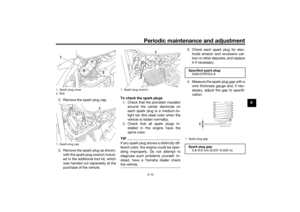
a fuel reserve tripmeter1. Speedometer
2. Odometer/tripmeter/fuel reserve tripme-
ter/clock
21
UBS5E0E0.book Page 5 Wednesday, October 19, 2016 10:21 AM
Page 21 of 88

Instrument and control functions
3-6
3
a clock
TIPThe key must be turned to “ON”
before you can use the “SELECT”
and “RESET” switches.
For the UK: To switch the speed-
ometer and odometer/tripmeter
displays between kilometers and
miles, push the “SELECT” switch
for at least three seconds.
Odometer, tripmeters, an d clock
The odometer shows the total distance
traveled by the vehicle.
The tripmeters show the distance trav-
eled since they were last reset.
The fuel reserve tripmeter shows the
distance traveled on the fuel reserve.
The clock displays time in 12-hour for-
mat.TIP The odometer will lock at 999999
km.
The tripmeters will reset and con-
tinue counting after 999.9 km is
reached.
In normal operation, push the “SE-
LECT” switch to change the display
between the odometer “ODO”, the
tripmeter “TRIP 1” and “TRIP 2”, and
the clock in the following order:
ODO → TRIP 1 → TRIP 2 → clock →
ODO
If the fuel level warning light comes on,
the display will change to the fuel re-
serve tripmeter “TRIP F” and start
counting the distance traveled from
that point. In this case, push the “SE-
LECT” switch to change the display in
the following order:
TRIP F → TRIP 1 → TRIP 2 → clock →
ODO → TRIP F
To reset a tripmeter, use the “SELECT”
switch to change the display to the de-
sired tripmeter and then push the “RE-
SET” switch for one second. The fuel
reserve tripmeter can be reset manual-
ly, or after refueling and traveling 5 km
(3 mi) it will reset automatically and dis-
appear from the display.
1. “SELECT” switch
2. “RESET” switch
1
2
1. Odometer/tripmeter/fuel reserve tripme- ter/clock
1
UBS5E0E0.book Page 6 Wednesday, October 19, 2016 10:21 AM
Page 22 of 88
Instrument and control functions
3-7
3 To set the clock
1. Push the “SELECT” and “RESET”
switches for three seconds. The
hour digits will start flashing.
2. Use the “SELECT” switch to set the hours.
3. Push the “RESET” switch. The mi- nute digits will start flashing.
4. Use the “SELECT” switch to set the minutes.
5. Push the “RESET” switch for two seconds to confirm setting chang-
es and start the clock.
EAU1234M
Han dle bar switchesLeft Ri
ght
EAU12352
Pass switch “ ”
Press this switch to flash the headlight.TIPWhen the dimmer switch is set
to “ ”, the passing switch has no ef-
fect.
EAU12401
Dimmer switch “ / ”
Set this switch to “ ” for the high
beam and to “ ” for the low beam.
1. Clock
1
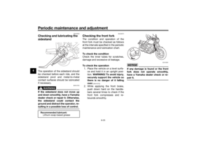
1. Pass switch “ ”
2. Dimmer switch “ / ”
3. Turn signal switch “ / ”
4. Horn switch “ ”
3
4 12
1. Engine stop switch “ / ”
2. “SELECT” switch
3. “RESET” switch
4. Start switch “ ”
5. Hazard switch “ ”
1
5 2
3
4
UBS5E0E0.book Page 7 Wednesday, October 19, 2016 10:21 AM
Page 23 of 88

Instrument and control functions
3-8
3
EAU12461
Turn si gnal switch “ / ”
To signal a right-hand turn, push this
switch to “ ”. To signal a left-hand
turn, push this switch to “ ”. When
released, the switch returns to the cen-
ter position. To cancel the turn signal
lights, push the switch in after it has re-
turned to the center position.
EAU12501
Horn switch “ ”
Press this switch to sound the horn.
EAU12662
En gine stop switch “ / ”
Set this switch to “ ” before starting
the engine. Set this switch to “ ” to
stop the engine in case of an emergen-
cy, such as when the vehicle overturns
or when the throttle cable is stuck.
EAU12713
Start switch “ ”
Push this switch to crank the engine
with the starter. See page 5-1 for start-
ing instructions prior to starting the en-
gine.
EAU12735
Hazar d switch “ ”
With the key in the “ON” or “ ” posi-
tion, use this switch to turn on the haz-
ard lights (simultaneous flashing of all
turn signal lights).
The hazard lights are used in case of an
emergency or to warn other drivers
when your vehicle is stopped where it
might be a traffic hazard.NOTICE
ECA10062
Do not use the hazar d lig hts for an
exten ded len gth of time with the en-
g ine not runnin g, otherwise the bat-
tery may d ischarge.
EAU55701
“SELECT” switch
This switch is used to perform selec-
tions in the odometer and tripmeters
and to set the clock of the multi-func-
tion meter unit.
See “Multi-function meter unit” on
page 3-5 for detailed information.
EAU55711
“RESET” switch
This switch is used to reset the tripme-
ters and to set the clock of the multi-
function meter unit.
See “Multi-function meter unit” on
page 3-5 for detailed information.
UBS5E0E0.book Page 8 Wednesday, October 19, 2016 10:21 AM
Page 24 of 88
Instrument and control functions
3-9
3
EAU12822
Clutch leverThe clutch lever is located on the left
side of the handlebar. To disengage
the clutch, pull the lever toward the
handlebar grip. To engage the clutch,
release the lever. The lever should be
pulled rapidly and released slowly for
smooth clutch operation.
The clutch lever is equipped with a
clutch switch, which is part of the igni-
tion circuit cut-off system. (See page
3-18.)
EAU12872
Shift pe dalThe shift pedal is located on the left
side of the motorcycle and is used in
combination with the clutch lever when
shifting the gears of the 5-speed con-
stant-mesh transmission equipped on
this motorcycle.
EAU12892
Brake leverThe brake lever is located on the right
side of the handlebar. To apply the
front brake, pull the lever toward the
throttle grip.
1. Clutch lever
1
1. Shift pedal
2. Neutral position
1
2
5
4
3
2
N 1 5
4
3
2
N 1
1. Brake lever
1
UBS5E0E0.book Page 9 Wednesday, October 19, 2016 10:21 AM