Page 81 of 88
Front tire:Type:
Tubeless
Size: 100/90-19M/C 57H
Manufacturer/model: BRIDGESTONE/EXEDRA G721 FRear tire:Type: Tubeless
Size: 150/80B16M/C 71H
Manufacturer/mod")
Specifications
8-2
8
Trail:130 mm (5.1 in)Front tire:Type:
Tubeless
Size: 100/90-19M/C 57H
Manufacturer/model: BRIDGESTONE/EXEDRA G721 FRear tire:Type: Tubeless
Size: 150/80B16M/C 71H
Manufacturer/model:
BRIDGESTONE/EXEDRA G722 FLoa din g:Maximum load:
201 kg (443 lb)
(Total weight of rider, passenger, cargo
and accessories)Tire air pressure (measure d on col d
tires):1 person:
Front:225 kPa (2.25 kgf/cm², 33 psi)
Rear:
250 kPa (2.50 kgf/cm², 36 psi)
2 persons: Front:
250 kPa (2.50 kgf/cm², 36 psi)
Rear: 280 kPa (2.80 kgf/cm², 41 psi)
Front wheel:Wheel type:Cast wheel
Rim size:
19M/C x MT2.50Rear wheel:Wheel type:Cast wheel
Rim size:
16M/C x MT3.50Front brake:Type:
Hydraulic single disc brake
Specified brake fluid:
DOT 4Rear brake:Type:
Hydraulic single disc brake
Specified brake fluid:
DOT 4Front suspension:Type:Telescopic fork
Spring:
Coil spring
Shock absorber: Hydraulic damper
Wheel travel: 120 mm (4.7 in)Rear suspension:Type:Swingarm
Spring: Coil spring Shock absorber:
Gas-hydraulic damper
Wheel travel: 70 mm (2.8 in)
Electrical system:System voltage:12 V
Ignition system: TCI
Charging system:
AC magnetoBattery:Model:YTZ14S
Voltage, capacity:
12 V, 11.2 Ah (10 HR)Hea dlig ht:Bulb type:
Halogen bulbBul b watta ge:Headlight:
H4, 60.0 W/55.0 W
Brake/tail light: LED
Front turn signal light:
21.0 W
Rear turn signal light: 21.0 W
Auxiliary light: 5.0 W
License plate light:
5.0 W
Meter lighting: LED
UBS5E0E0.book Page 2 Wednesday, October 19, 2016 10:21 AM
Page 82 of 88
Specifications
8-3
8
Neutral indicator light:LED
High beam indicator light: LED
Oil level warning light:
LED
Turn signal indicator light: LED
Fuel level warning light: LED
Engine trouble warning light:
LED
ABS warning light: LED
Immobilizer system indicator light: LEDFuse(s):Main fuse:40.0 A
Headlight fuse: 20.0 A
Signaling system fuse:
7.5 A
Ignition fuse: 15.0 A
Parking lighting fuse: 15.0 A
Fuel injection system fuse:
10.0 A
ABS control unit fuse: 7.5 A
ABS motor fuse: 30.0 A ABS solenoid fuse:
15.0 A
Backup fuse: 7.5 A
UBS5E0E0.book Page 3 Wednesday, October 19, 2016 10:21 AM
Page 83 of 88
Consumer information
9-1
9
EAU53562
Id entification num bersRecord the vehicle identification num-
ber, engine serial number, and the
model label information in the spaces
provided below. These identification
numbers are needed when registering
the vehicle with the authorities in your
area and when ordering spare parts
from a Yamaha dealer.
VEHICLE IDENTIFICATION NUMBER:
ENGINE SERIAL NUMBER:
MODEL LABEL INFORMATION:
EAU26401
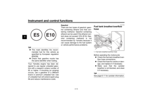
Vehicle i dentification num ber
The vehicle identification number is
stamped into the steering head pipe.
Record this number in the space pro-
vided.TIPThe vehicle identification number is
used to identify your motorcycle and
may be used to register your motorcy-
cle with the licensing authority in your
area.
EAU26442
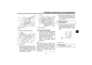
En gine serial num ber
The engine serial number is stamped
into the crankcase.
EAU26471
Mo del la bel
1. Vehicle identification number
1
1. Engine serial number
1. Model label
1
1
UBS5E0E0.book Page 1 Wednesday, October 19, 2016 10:21 AM
Page 84 of 88

Record the information on this label in
the space provided. This information
will be needed whe")
Consumer information
9-2
9The model label is affixed to the frame
under the rider seat. (See page 3-15.)
Record the information on this label in
the space provided. This information
will be needed when ordering spare
parts from a Yamaha dealer.
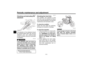
EAU69910
Dia
gnostic connectorThe diagnostic connector is located as
shown.
EAU74701
Vehicle data recor din gThis model’s ECU stores certain vehi-
cle data to assist in the diagnosis of
malfunctions and for research and de-
velopment purposes. This data will be
uploaded only when a special Yamaha
diagnostic tool is attached to the vehi-
cle, such as when maintenance checks
or service procedures are performed.
Although the sensors and recorded
data will vary by model, the main data
points are:
Vehicle status and engine perfor-
mance data
Fuel-injection and emission-relat-
ed data
Yamaha will not disclose this data to a third party except: With the consent of the vehicle
owner
Where obligated by law
For use by Yamaha in litigation
For general Yamaha-conducted
research purposes when the data
is not related to an individual vehi-
cle nor owner
1. Diagnostic connector
1
UBS5E0E0.book Page 2 Wednesday, October 19, 2016 10:21 AM
Page 85 of 88

10-1
10
Index
AABS....................................................... 3-10
ABS warning light ................................... 3-4
Air filter element, replacing ................... 6-14
Auxiliary light bulb, replacing ............... 6-30BBattery .................................................. 6-26
Brake and clutch levers, checking and
lubricating........................................... 6-24
Brake and shift pedals, checking and lubricating........................................... 6-23
Brake fluid, changing............................ 6-22
Brake fluid level, checking.................... 6-20
Brake lever.............................................. 3-9
Brake lever free play, checking ............ 6-19
Brake light switches ............................. 6-19
Brake pedal .......................................... 3-10
Brake/tail light....................................... 6-31CCables, checking and lubricating ......... 6-23
Canister ................................................ 6-11
Care ........................................................ 7-1
Catalytic converter ............................... 3-14
Clutch lever............................................. 3-9
Clutch lever free play, adjusting ........... 6-18DData recording, vehicle........................... 9-2
Diagnostic connector ............................. 9-2
Dimmer switch........................................ 3-7
Drive belt slack ..................................... 6-22EEngine break-in ...................................... 5-3
Engine oil and oil filter cartridge ........... 6-11
Engine serial number .............................. 9-1 Engine stop switch................................. 3-8
Engine trouble warning light .................. 3-4
FFront and rear brake pads, checking ... 6-20
Front fork, checking ............................. 6-25
Fuel ...................................................... 3-12
Fuel consumption, tips for reducing ...... 5-3
Fuel level warning light........................... 3-4
Fuel tank breather/overflow hose ........ 3-13
Fuel tank cap........................................ 3-11
Fuses, replacing ................................... 6-28HHandlebar switches ............................... 3-7
Hazard switch ........................................ 3-8
Headlight bulb, replacing ..................... 6-29
High beam indicator light ....................... 3-3
Horn switch ............................................ 3-8IIdentification numbers ........................... 9-1
Ignition circuit cut-off system .............. 3-18
Immobilizer system ................................ 3-1
Immobilizer system indicator light ......... 3-5
Indicator lights and warning lights ......... 3-3LLicense plate light ................................ 6-32MMain switch ............................................ 3-2
Maintenance and lubrication, periodic... 6-5
Maintenance, emission control
system ................................................. 6-3
Matte color, caution ............................... 7-1
Model label............................................. 9-1
Multi-function meter unit ........................ 3-5
NNeutral indicator light ............................. 3-3OOil level warning light .............................. 3-3PPanel, removing and installing ................ 6-9
Parking.................................................... 5-4
Part locations.......................................... 2-1
Pass switch............................................. 3-7RRESET switch ......................................... 3-8
Rider seat.............................................. 3-15SSafety information................................... 1-1
SELECT switch ....................................... 3-8
Shifting.................................................... 5-2
Shift pedal............................................... 3-9
Shock absorber assemblies, adjusting ............................................. 3-16
Sidestand.............................................. 3-17
Sidestand, checking and lubricating .... 6-25
Spark plugs, checking ............................ 6-9
Specifications ......................................... 8-1
Starting the engine ................................. 5-1
Start switch ............................................. 3-8
Steering, checking ................................ 6-26
Steering lock ......................................... 3-14
Storage ................................................... 7-3
Supporting the motorcycle ................... 6-32TThrottle grip and cable, checking and lubricating ........................................... 6-23
Throttle grip free play, checking ........... 6-15
Tires ...................................................... 6-16
UBS5E0E0.book Page 1 Wednesday, October 19, 2016 10:21 AM
Page 86 of 88
Index
10-2
10
Tool kit .................................................... 6-2
Troubleshooting .................................... 6-33
Troubleshooting chart........................... 6-34
Turn signal indicator light ....................... 3-3
Turn signal light bulb, replacing............ 6-31
Turn signal switch ................................... 3-8VValve clearance..................................... 6-15
Vehicle identification number ................. 9-1WWheel bearings, checking..................... 6-26
Wheels .................................................. 6-17
UBS5E0E0.book Page 2 Wednesday, October 19, 2016 10:21 AM
Page 87 of 88
UBS5E0E0.book Page 3 Wednesday, October 19, 2016 10:21 AM
Page 88 of 88
DIC183
PRINTED ON RECYCLED PAPER
Original instructions
PRINTED IN JAPAN2016.11-0.3×3 CR (E)


")