Page 25 of 88

Instrument and control functions
3-10
3
EAU12944
Brake ped alThe brake pedal is located on the right
side of the motorcycle. To apply the
rear brake, press down on the brake
pedal.
EAU63040
ABSThe Yamaha ABS (Anti-lock Brake
System) features a dual electronic con-
trol system, which acts on the front and
rear brakes independently.
Operate the brakes with ABS as you
would conventional brakes. If the ABS
is activated, a pulsating sensation may
be felt at the brake lever or brake ped-
al. In this situation, continue to apply
the brakes and let the ABS work; do
not “pump” the brakes as this will re-
duce braking effectiveness.
WARNING
EWA16051
Always keep a sufficient d istance
from the vehicle ahea d to match the
ri din g speed even with ABS.
The ABS performs best with
lon g b rakin g d istances.
On certain surfaces, such as
rou gh or g ravel roa ds, the b rak-
in g d istance may be lon ger with
the ABS than without.The ABS is monitored by an ECU,
which will revert the system to conven-
tional braking if a malfunction occurs.
TIP The ABS performs a self-diagno-
sis test each time the vehicle first
starts off after the key is turned to
“ON” and the vehicle has traveled
at a speed of 10 km/h (6 mi/h) or
higher. During this test, a “click-
ing” noise can be heard from the
hydraulic control unit, and if the
brake lever or brake pedal is even
slightly applied, a vibration can be
felt at the lever and pedal, but
these do not indicate a malfunc-
tion.
This ABS has a test mode which
allows the owner to experience
the pulsation at the brake lever or
brake pedal when the ABS is op-
erating. However, special tools are
required, so please consult your
Yamaha dealer.NOTICE
ECA20100
Be careful not to d amage the wheel
sensor or wheel sensor rotor; other-
wise, improper performance of the
ABS will result.
1. Brake pedal
1
UBS5E0E0.book Page 10 Wedne sday, October 19, 2016 10:21 AM
Page 26 of 88

Instrument and control functions
3-11
3
EAU13125
Fuel tank capTo remove the fuel tank cap
Slide the fuel tank cap lock cover open,
insert the key into the lock, and then
turn it 1/4 turn clockwise. The lock will
be released and the fuel tank cap can
be removed.
To install the fuel tank cap
1. Insert the fuel tank cap into the tank opening with the key inserted
in the lock and with the “ ” mark
facing forward. 2. Turn the key counterclockwise to
the original position, remove it,
and then close the lock cover.
TIPThe fuel tank cap cannot be installed
unless the key is in the lock. In addi-
tion, the key cannot be removed if the
cap is not properly installed and
locked.
WARNING
EWA10132
Make sure that the fuel tank cap is
properly installe d before ri din g.
Leakin g fuel is a fire hazar d.
1. Front wheel sensor rotor
2. Front wheel sensor
1. Rear wheel sensor rotor
2. Rear wheel sensor1
21
2
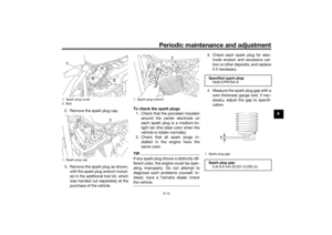
1. Fuel tank cap lock cover
2. “ ” mark
3. Lock.
4. Unlock.1
2 4
3
UBS5E0E0.book Page 11 Wedne
sday, October 19, 2016 10:21 AM
Page 27 of 88

Instrument and control functions
3-12
3
EAU13222
FuelMake sure there is sufficient gasoline in
the tank.
WARNING
EWA10882
Gasoline an d gasoline vapors are
extremely flammab le. To avoid fires
an d explosions an d to re duce the
risk of injury when refuelin g, follow
these instructions.1. Before refueling, turn off the en- gine and be sure that no one is sit-
ting on the vehicle. Never refuel
while smoking, or while in the vi-
cinity of sparks, open flames, or
other sources of ignition such as
the pilot lights of water heaters
and clothes dryers.
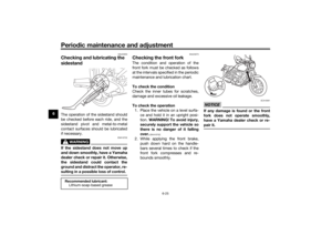
2. Do not overfill the fuel tank. When refueling, be sure to insert the
pump nozzle into the fuel tank filler
hole. Stop filling when the fuel
reaches the bottom of the filler
tube. Because fuel expands when
it heats up, heat from the engine or
the sun can cause fuel to spill out
of the fuel tank. 3. Wipe up any spilled fuel immedi-
ately. NOTICE: Immediately
wipe off spille d fuel with a clean,
d ry, soft cloth, since fuel may
d eteriorate painte d surfaces or
plastic parts.
[ECA10072]
4. Be sure to securely close the fuel tank cap.
WARNING
EWA15152
Gasoline is poisonous an d can cau-
se injury or death. Han dle gasoline
with care. Never siphon gasoline by
mouth. If you shoul d swallow some
g asoline or inhale a lot of gasoline
vapor, or get some g asoline in your
eyes, see your d octor immediately. If g
asoline spills on your skin, wash
with soap an d water. If g asoline
spills on your clothin g, chan ge your
clothes.
EAU57692
NOTICE
ECA11401
Use only unlea ded g asoline. The use
of lead ed g asoline will cause severe
d amag e to internal en gine parts,
such as the valves an d piston rin gs,
as well as to the exhaust system.
1. Fuel tank filler tube
2. Maximum fuel level
2
1
Recommen ded fuel:
Regular unleaded gasoline (Gasohol
[E10] acceptable)
Fuel tank capacity:
13 L (3.4 US gal, 2.9 Imp.gal)
Fuel reserve amount (when the fuel
level warnin g li ght comes on):
2.8 L (0.74 US gal, 0.62 Imp.gal)
UBS5E0E0.book Page 12 Wedne sday, October 19, 2016 10:21 AM
Page 28 of 88
.
Check that gasoline nozzle has
the same iden")
Instrument and control functions
3-13
3
TIPThis mark identifies the recom-
mended fuel for this vehicle as
specified by European regulation
(EN228).
Check that gasoline nozzle has
the same identifier when fueling.Your Yamaha engine has been de-
signed to use regular unleaded gaso-
line with a research octane number of
95 or higher. If knocking (or pinging)
occurs, use a gasoline of a different
brand or premium unleaded fuel. Use
of unleaded fuel will extend spark plug
life and reduce maintenance costs. Gasohol
There are two types of gasohol: gaso-
hol containing ethanol and that con-
taining methanol. Gasohol containing
ethanol can be used if the ethanol con-
tent does not exceed 10% (E10). Gas-
ohol containing methanol is not
recommended by Yamaha because it
can cause damage to the fuel system
or vehicle performance problems.
EAU77630
Fuel tank breather/overflow
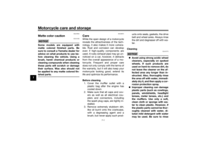
hoseBefore operating the motorcycle:
Check the fuel tank breather/over-
flow hose connections.
Check the hose for cracks or dam-
age, and replace it if necessary.
Make sure that the canister
breather is not blocked, and clean
it if necessary.TIPSee page 6-11 for canister information.
E5
E10
1. Fuel tank breather/overflow hose
1
UBS5E0E0.book Page 13 Monday, May 21, 2018 5:59 PM
Page 29 of 88

Instrument and control functions
3-14
3
EAU13434
Catalytic converterThis model is equipped with a catalytic
converter in the exhaust system.
WARNING
EWA10863
The exhaust system is hot after op-
eration. To prevent a fire hazar d or
b urns:
Do not park the vehicle near
possi ble fire hazar ds such as
g rass or other materials that
easily burn.
Park the vehicle in a place
where pe destrians or chil dren
are not likely to touch the hot
exhaust system.
Make sure that the exhaust sys-
tem has coole d down before
d oin g any maintenance work.
Do not allow the en gine to i dle
more than a few minutes. Lon g
i d lin g can cause a buil d-up of
heat.
NOTICE
ECA10702
Use only unlea ded g asoline. The use
of lead ed g asoline will cause unre-
paira ble damag e to the catalytic
converter.
EAU55663
Steerin g lockThe steering lock is located on the right
side of the vehicle between the upper
and lower steering brackets.
To lock the steerin g
1. Turn the handlebar all the way to the left.
2. Insert the key into the steering lock and turn it 1/2 turn clockwise.
3. Remove the key from the lock.TIPIf the steering lock is difficult to en-
gage, try turning the handlebars back
to the right slightly.1. Steering lock
2. Lock.
L O CKUNLO CK
1
2
UBS5E0E0.book Page 14 Wedne
sday, October 19, 2016 10:21 AM
Page 30 of 88
Instrument and control functions
3-15
3 To unlock the steerin
g
1. Insert the key into the steering lock.
2. Turn the key 1/2 turn counter- clockwise.
3. Remove the key.
EAU55822
Ri der seatTo remove the ri der seat
1. Remove panel A. (See page 6-9.)
2. Remove the bolt.
3. Lift the front of the rider seat up, and then pull the rider seat off.
To install the ri der seat
1. Insert the projection on the rear of the rider seat into the seat holder
as shown. 2. Place the rider seat in the original
position.
3. While pushing the front of the rider seat down so that there is no
space between the rubber damp-
ers and the frame, tighten the bolt
to the specified torque.
1. Unlock.
LO CKUNLO CK
1
1. Bolt
1
1. Projection
2. Seat holder
21
UBS5E0E0.book Page 15 Wedne sday, October 19, 2016 10:21 AM
Page 31 of 88

Instrument and control functions
3-16
3
4. Install the panel.
TIPMake sure that the rider seat is proper-
ly secured before riding.
EAU57770
A djustin g the shock a bsor ber
assem blies
WARNING
EWA10211
Always a djust both shock ab sorber
assem blies equally, otherwise poor
han dlin g an d loss of sta bility may re-
sult.Each shock absorber assembly is
equipped with a spring preload adjust-
ing ring.
When making this adjustment, use the
special wrench and extension bar in-
cluded in the additional tool kit, which
was handed out separately at the pur-
chase of the vehicle.NOTICE
ECA10102
To avoi d d amag ing the mechanism,
d o not attempt to turn b eyond the
maximum or minimum settin gs.Adjust the spring preload as follows.
To increase the spring preload and
thereby harden the suspension, turn
the adjusting ring on each shock ab-
sorber assembly in direction (a). To de-
crease the spring preload and thereby soften the suspension, turn the adjust-
ing ring on each shock absorber as-
sembly in direction (b).
1. Rubber damperTi
ghtenin g torque:
Rider seat fitting bolt: 16 N·m (1.6 kgf·m, 12 lb·ft)1
1. Extension bar
2. Special wrench
3. Spring preload adjusting ring
4. Position indicator
Sprin g preloa d settin g:
Minimum (soft): 0 notch(es) in direction (a)*
Standard: 1 notch(es) in direction (a)*
Maximum (hard):
4 notch(es) in direction (a)*
* With the adjusting ring fully turned in direction (b)
3
(a)
(b)
2
1
4
UBS5E0E0.book Page 16 Wedne sday, October 19, 2016 10:21 AM
Page 32 of 88

Instrument and control functions
3-17
3
WARNING
EWA10232
These shock ab sorber assem blies
contain hi ghly pressurize d nitro gen
g as. Rea d an d un derstan d the fol-
lowin g information before han dlin g
the shock a bsor ber assem blies.
Do not tamper with or attempt
to open the cylin der assem blies.
Do not su bject the shock a b-
sor ber assem blies to an open
flame or other hi gh heat source.
This may cause the unit to ex-
plo de due to excessive gas
pressure.
Do not d eform or d amage the
cylin ders in any way. Cylin der
d amag e will result in poor
d ampin g performance.
Do not dispose of a damag ed or
worn-out shock a bsor ber as-
sem bl
y yourself. Take the shock
a b sor ber assem bly to a Yamaha
d ealer for any service.
EAU15306
Si destan dThe sidestand is located on the left
side of the frame. Raise the sidestand
or lower it with your foot while holding
the vehicle upright.TIPThe built-in sidestand switch is part of
the ignition circuit cut-off system,
which cuts the ignition in certain situa-
tions. (See the following section for an
explanation of the ignition circuit cut-
off system.)
WARNING
EWA10242
The vehicle must not be ri dden with
the si destan d d own, or if the si de-
stan d cannot b e properly moved up
(or does not stay up), otherwise the
si destan d coul d contact the groun d
an d d istract the operator, resultin g
in a possi ble loss of control.
Yamaha’s ig nition circuit cut-off
system has been desi gne d to assist
the operator in fulfillin g the respon-
si bility of raisin g the si destan d b e-
fore startin g off. Therefore, check this system reg
ularly and have a
Yamaha dealer repair it if it does not
function properly.
UBS5E0E0.book Page 17 Wedne sday, October 19, 2016 10:21 AM