Page 49 of 120

Instrument and control functions
3-35
3
distance A is, the higher the spring pre-
load; the longer distance A is, the lower
the spring preload.
Re
boun d d ampin g force
To increase the rebound damping for-
ce and thereby harden the rebound
damping, turn the adjusting screw on
each fork leg in direction (a). To de-
crease the rebound damping force and
thereby soften the rebound damping,
turn the adjusting screw on each fork
leg in direction (b). Compression
dampin g force
To increase the compression damping
force and thereby harden the com-
pression damping, turn the adjusting
screw on each fork leg in direction (a).
To decrease the compression damp-
ing force and thereby soften the com-
pression damping, turn the adjusting
screw on each fork leg in direction (b).
1. Distance A
Sprin g preloa d settin g:
Minimum (soft): Distance A = 19.0 mm (0.75 in)
Standard: Distance A = 14.0 mm (0.55 in)
Maximum (hard):
Distance A = 4.0 mm (0.16 in)
1. Rebound damping force adjusting screw
1
1
(a)
(b)
Re boun d d ampin g settin g:
Minimum (soft): 10 click(s) in direction (b)*
Standard:
8 click(s) in direction (b)*
Maximum (hard): 1 click(s) in direction (b)*
* With the adjusting screw fully turned in direction (a)
1. Compression damping force adjusting
screw
Compression dampin g settin g:
Minimum (soft):
13 click(s) in direction (b)*
Standard: 6 click(s) in direction (b)*
Maximum (hard): 1 click(s) in direction (b)*
* With the adjusting screw fully
turned in direction (a)
1
(a)
(b)
UBP8E0E0.book Page 35 Thursday, December 8, 2016 7:25 PM
Page 50 of 120

Instrument and control functions
3-36
3
TIP
Although the total number of clicks of a
damping force adjusting mechanism
may not exactly match the above
specifications due to small differences
in production, the actual number of
clicks always represents the entire ad-
justing range. To obtain a precise ad-
justment, it would be advisable to
check the number of clicks of each
damping force adjusting mechanism
and to modify the specifications as
necessary.
EAU49692
A djustin g the shock a bsor ber
assem bly
This shock absorber assembly is
equipped with a spring preload adjust-
ing knob and a rebound damping force
adjusting knob.
NOTICE
ECA10102
To avoi d d amag ing the mechanism,
d o not attempt to turn beyon d the
maximum or minimum settin gs.
Sprin g preloa d
To increase the spring preload and
thereby harden the suspension, turn
the adjusting knob in direction (a). To
decrease the spring preload and there-
by soften the suspension, turn the ad-
justing knob in direction (b). NOTICE:
To avoi d damag ing the a djustin g
kno b, d o not turn the a djustin g kno b
while sittin g on the vehicle.
[ECA20110]
TIP
Align the appropriate mark on the
adjusting mechanism with the
matching edge.
When adjusting the spring pre-
load, there should be no weight on
the rear of the vehicle.
1. Spring preload adjusting knob
2. Matching edge
SOFT
HARD1(b)
(a)
6
5
4
3
2
12
UBP8E0E0.book Page 36 Thursday, December 8, 2016 7:25 PM
Page 51 of 120
. To decreas")
Instrument and control functions
3-37
3
Re
boun d d ampin g force
To increase the rebound damping for-
ce and thereby harden the rebound
damping, turn the adjusting knob in di-
rection (a). To decrease the rebound
damping force and thereby soften the
rebound damping, turn the adjusting
knob in direction (b).
TIP
To obtain a precise adjustment, it is
advisable to check the actual total
number of clicks or turns of each
damping force adjusting mechanism. This adjustment range may not exactly
match the specifications listed due to
small differences in production.
WARNING
EWA10222
This shock ab
sorber assem bly con-
tains hig hly pressurize d nitro gen
g as. Rea d an d un derstan d the fol-
lowin g information before han dlin g
the shock a bsor ber assem bly.
Do not tamper with or attempt
to open the cylind er assembly.
Do not su bject the shock a b-
sor ber assem bly to an open
flame or other hi gh heat source.
This may cause the unit to ex-
plo de due to excessive gas
pressure.
Do not deform or damag e the
cylin der in any way. Cylin der
d amag e will result in poor
d ampin g performance.
Do not dispose of a d amaged or
worn-out shock a bsor ber as-
sem bly
yourself. Take the shock
a b sor ber assem bly to a Yamaha
d ealer for any service.
Sprin g preloa d settin g:
Minimum (soft): 6
Standard:
4
Maximum (hard): 1
1. Rebound damping force adjusting knob
Re boun d d ampin g settin g:
Minimum (soft): 20 clicks in direction (b)*
Standard:
10 clicks in direction (b)*
Maximum (hard): 1 clicks in direction (b)*
* With the adjusting knob fully turned in direction (a)
1
(b)
(a)
UBP8E0E0.book Page 37 Thursday, December 8, 2016 7:25 PM
Page 52 of 120
Instrument and control functions
3-38
3
EAU49703
Carriers
This motorcycle is equipped with a
standard carrier, and with an additional
carrier, located under the passenger
seat. This additional carrier extends the
loading surface and the loading capac-
ity of the standard carrier.
To use the additional carrier, consult a
Yamaha dealer.
Stan dar d carrier
A dditional carrier
WARNING
EWA15483
Do not exceed the maximum
loa d of 212 k g (467 l b) for the ve-
hicle.
Do not sit on an d never ri de with
a passen ger on the stan dar d or
a dditional carrier.
Do not exceed the standar d car-
rier capacity of 5.0 k g (11 lb ).
Do not exceed the additional
carrier capacity of 5.0 kg (11 lb).
NOTICE
ECA16822
Do not lift the vehicle b y either carri-
er.
1. Standard carrier
1. Additional carrier
1
1
UBP8E0E0.book Page 38 Thursday, December 8, 2016 7:25 PM
Page 53 of 120

Instrument and control functions
3-39
3
EAU49491
Lugg ag e strap hol ders
There are four luggage strap holders
below the passenger seat.
EAU15306
Si destan d
The sidestand is located on the left
side of the frame. Raise the sidestand
or lower it with your foot while holding
the vehicle upright.
TIP
The built-in sidestand switch is part of
the ignition circuit cut-off system,
which cuts the ignition in certain situa-
tions. (See the following section for an
explanation of the ignition circuit cut-
off system.)
WARNING
EWA10242
The vehicle must not be ri dden with
the si destan d d own, or if the si de-
stan d cannot b e properly move d up
(or does not stay up), otherwise the
si destan d coul d contact the g round
an d d istract the operator, resultin g
in a possi ble loss of control.
Yamaha’s ig nition circuit cut-off
system has been desi gne d to assist
the operator in fulfillin g the respon-
si bility of raisin g the si destan d b e-
fore startin g off. Therefore, check
this system re gularly an d have a
Yamaha dealer repair it if it does not
function properly.
1. Luggage strap holder
1
UBP8E0E0.book Page 39 Thursday, December 8, 2016 7:25 PM
Page 54 of 120
Instrument and control functions
3-40
3
EAU64050
Ig nition circuit cut-off system
The ignition circuit cut-off system
(comprising the sidestand switch,
clutch switch and neutral switch) has
the following functions.
It prevents starting when the
transmission is in gear and the
sidestand is up, but the clutch le-
ver is not pulled.
It prevents starting when the
transmission is in gear and the
clutch lever is pulled, but the side-
stand is still down.
It cuts the running engine when
the transmission is in gear and the
sidestand is moved down.
Periodically check the operation of the
ignition circuit cut-off system accord-
ing to the following procedure.
UBP8E0E0.book Page 40 Thursday, December 8, 2016 7:25 PM
Page 55 of 120

Instrument and control functions
3-41
3
With the engine turned off:
1. Move the sidestand down.
2.
Make sure that the start/engine stop
switch is set to “ ”.
3. Turn the key on.
4. Shift the transmission into the neutral position.
5.
Push the “ ” side of the start/engine
stop switch.
Does the engine start?
With the engine still running:
6. Move the sidestand up.
7. Keep the clutch lever pulled.
8. Shift the transmission into gear.
9. Move the sidestand down.
Does the engine stall?
After the engine has stalled:
10. Move the sidestand up.
11. Keep the clutch lever pulled.
12.
Push the “ ” side of the
start/engine stop switch.
Does the engine start?
The system is OK. The motorcycle can
be ridden.
The neutral switch may not be working
correctly.
The motorcycle should not be ridden
until checked by a Yamaha dealer.
The sidestand switch may not be
working correctly.
The motorcycle should not be ridden
until checked by a Yamaha dealer.
The clutch switch may not be working
correctly.
The motorcycle should not be ridden
until checked by a Yamaha dealer.
WARNING
If a malfunction is noted, have a
Yamaha dealer check the system
before riding.
YES NO
YESNO
YESNO
UBP8E0E0.book Page 41 Thursday, December 8, 2016 7:25 PM
Page 56 of 120

Instrument and control functions
3-42
3
EAU49453
Auxiliary DC jack
WARNING
EWA14361
To prevent electrical shock or short-
circuitin g, make sure that the cap is
installe d when the auxiliary DC jack
is not b eing use d.
NOTICE
ECA15432
The accessory connecte d to the
auxiliary DC jack shoul d not b e used
with the en gine turne d off, an d the
loa d must never exceed 30 W (2.5 A),
otherwise the fuse may blow or the
b attery may d ischarge.
This vehicle is equipped with an auxil-
iary DC jack.
A 12-V accessory connected to the
auxiliary DC jack can be used when the
key is in the “ON” position and should
only be used when the engine is run-
ning.
To use the auxiliary DC jack
1. Turn the key to “OFF”.
2. Remove the auxiliary DC jack cap.
3. Turn the accessory off.
4. Insert the accessory plug into the auxiliary DC jack. 5. Turn the key to “ON”, and then
start the engine. (See page 5-2.)
6. Turn the accessory on.
1. Auxiliary DC jack cap
1
1. Auxiliary DC jack
1
UBP8E0E0.book Page 42 Thursday, December 8, 2016 7:25 PM
 1
1 2
2 3
3 4
4 5
5 6
6 7
7 8
8 9
9 10
10 11
11 12
12 13
13 14
14 15
15 16
16 17
17 18
18 19
19 20
20 21
21 22
22 23
23 24
24 25
25 26
26 27
27 28
28 29
29 30
30 31
31 32
32 33
33 34
34 35
35 36
36 37
37 38
38 39
39 40
40 41
41 42
42 43
43 44
44 45
45 46
46 47
47 48
48 49
49 50
50 51
51 52
52 53
53 54
54 55
55 56
56 57
57 58
58 59
59 60
60 61
61 62
62 63
63 64
64 65
65 66
66 67
67 68
68 69
69 70
70 71
71 72
72 73
73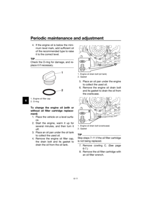 74
74 75
75 76
76 77
77 78
78 79
79 80
80 81
81 82
82 83
83 84
84 85
85 86
86 87
87 88
88 89
89 90
90 91
91 92
92 93
93 94
94 95
95 96
96 97
97 98
98 99
99 100
100 101
101 102
102 103
103 104
104 105
105 106
106 107
107 108
108 109
109 110
110 111
111 112
112 113
113 114
114 115
115 116
116 117
117 118
118 119
119
 has
the follow")