Page 41 of 120
Instrument and control functions
3-27
3
4. Have a Yamaha dealer check the
vehicle and turn off the engine
trouble warning light.
EAU13075
Fuel tank cap
To open the fuel tank cap
Open the fuel tank cap lock cover, in-
sert the key into the lock, and then turn
it 1/4 turn clockwise. The lock will be
released and the fuel tank cap can be
opened.
To close the fuel tank cap1. Push the fuel tank cap into posi- tion with the key inserted in the
lock.
2. Turn the key counterclockwise to the original position, remove it,
and then close the lock cover.
TIP
The fuel tank cap cannot be closed un-
less the key is in the lock. In addition,
the key cannot be removed if the cap is
not properly closed and locked.
WARNING
EWA11092
Make sure that the fuel tank cap is
properly close d after fillin g fuel.
Leakin g fuel is a fire hazar d.
1. Unlock.
2. Fuel tank cap lock cover
2
1
UBP8E0E0.book Page 27 Thursday, December 8, 2016 7:25 PM
Page 42 of 120

Instrument and control functions
3-28
3
EAU13222
Fuel
Make sure there is sufficient gasoline in
the tank.
WARNING
EWA10882
Gasoline and gasoline vapors are
extremely flammable. To avoid fires
and explosions and to reduce the
risk of injury when refueling, follow
these instructions.
1. Before refueling, turn off the en-gine and be sure that no one is sit-
ting on the vehicle. Never refuel
while smoking, or while in the vi-
cinity of sparks, open flames, or
other sources of ignition such as
the pilot lights of water heaters
and clothes dryers.
2. Do not overfill the fuel tank. When refueling, be sure to insert the
pump nozzle into the fuel tank filler
hole. Stop filling when the fuel
reaches the bottom of the filler
tube. Because fuel expands when
it heats up, heat from the engine or
the sun can cause fuel to spill out
of the fuel tank. 3. Wipe up any spilled fuel immedi-
ately. NOTICE: Immediately
wipe off spilled fuel with a clean,
dry, soft cloth, since fuel may
deteriorate painted surfaces or
plastic parts.
[ECA10072]
4. Be sure to securely close the fuel tank cap.
WARNING
EWA15152
Gasoline is poisonous and can cau-
se injury or death. Handle gasoline
with care. Never siphon gasoline by
mouth. If you should swallow some
gasoline or inhale a lot of gasoline
vapor, or get some gasoline in your
eyes, see your doctor immediately. If
gasoline spills on your skin, wash
with soap and water. If gasoline
spills on your clothing, change your
clothes.
EAU75300
NOTICE
ECA11401
Use only unleaded gasoline. The use
of leaded gasoline will cause severe
damage to internal engine parts,
such as the valves and piston rings,
as well as to the exhaust system.
1. Fuel tank filler tube
2. Maximum fuel level
21
Recommended fuel:Premium unleaded gasoline (Gaso-
hol [E10] acceptable)
Fuel tank capacity: 23 L (6.1 US gal, 5.1 Imp.gal)
Fuel reserve amount:
3.9 L (1.03 US gal, 0.86 Imp.gal)
UBP8E0E0.book Page 28 Wednesday, December 14, 2016 1:14 PM
Page 43 of 120
.
Check that gasoline nozzle has
the same iden")
Instrument and control functions
3-29
3TIP
This mark identifies the recom-
mended fuel for this vehicle as
specified by European regulation
(EN228).
Check that gasoline nozzle has
the same identifier when fueling.
Your Yamaha engine has been de-
signed to use premium unleaded gas-
oline with a research octane number of
95 or higher. If knocking (or pinging)
occurs, use a gasoline of a different
brand. Use of unleaded fuel will extend
spark plug life and reduce mainte-
nance costs.
Gasohol
There are two types of gasohol: gaso-
hol containing ethanol and that con-
taining methanol. Gasohol containing
ethanol can be used if the ethanol con-
tent does not exceed 10% (E10). Gas-
ohol containing methanol is not
recommended by Yamaha because it
can cause damage to the fuel system
or vehicle performance problems.
EAU79161
Fuel tank overflow hose
TIP
See page 6-10 for breather hose infor-
mation.
Before operating the motorcycle:
Check the fuel tank overflow hose
connection.
Check the fuel tank overflow hose
for cracks or damage, and replace
it if necessary.
Make sure that the end of the fuel
tank overflow hose is not blocked,
and clean it if necessary.
Make sure that the fuel tank over-
flow hose is positioned outside of
the cowling.
E10
1. Fuel tank overflow hose
1
UBP8E0E0.book Page 29 Wednesday, December 14, 2016 1:14 PM
Page 44 of 120

Instrument and control functions
3-30
3
EAU13434
Catalytic converter
This model is equipped with a catalytic
converter in the exhaust system.
WARNING
EWA10863
The exhaust system is hot after op-
eration. To prevent a fire hazar d or
b urns:
Do not park the vehicle near
possi ble fire hazard s such as
g rass or other materials that
easily burn.
Park the vehicle in a place
where pe destrians or chil dren
are not likely to touch the hot
exhaust system.
Make sure that the exhaust sys-
tem has coole d down before
d oin g any maintenance work.
Do not allow the en gine to id le
more than a few minutes. Lon g
i d lin g can cause a b uild-up of
heat.
NOTICE
ECA10702
Use only unlea ded g asoline. The use
of lead ed g asoline will cause unre-
pairab le dama ge to the catalytic
converter.
EAU49444
Ri der seat
To remove the ri der seat
1. Insert the key into the seat lock, and then turn it counterclockwise.
2. Lift the front of the rider seat and push the seat forward.
To install the ri der seat
1. Insert the projection on the rear of the rider seat into the seat holder
as shown, and then push the front
of the seat down to lock it in place.
2. Remove the key.
TIP
Make sure that the rider seat is
properly secured before riding.
1. Unlock.
2. Seat lock
1. Projection
2. Seat holder
2
1
1
2
UBP8E0E0.book Page 30 Thursday, December 8, 2016 7:25 PM
Page 45 of 120
Instrument and control functions
3-31
3
The rider seat height can be ad-
justed to change the riding posi-
tion. (See “Adjusting the rider seat
height”.)
EAU49475
Adjustin g the ri der seat hei ght
The rider seat height can be adjusted
to one of two positions to suit the rid-
er’s preference.
The rider seat height was adjusted to
the higher position at delivery.
To chan ge the ri der seat hei ght to
the low position 1. Remove the rider seat. (See page 3-30.)
2. Remove the rider seat height posi- tion adjuster by pulling it out.
3. Install the rider seat height posi- tion adjuster so that the match
mark is aligned with the “L” mark
as shown.
1. Low position
2. High position
1. Rider seat height position adjuster
12
1
UBP8E0E0.book Page 31 Thursday, December 8, 2016 7:25 PM
Page 46 of 120
Instrument and control functions
3-32
3
4. Insert the projection on the rear ofthe rider seat into seat holder A as
shown.
To chan ge the ri der seat hei ght to
the hi gh position
1. Remove the rider seat. (See page 3-30.)
2. Remove the rider seat height posi- tion adjuster by pulling it out. 3. Install the rider seat height posi-
tion adjuster so that the match
mark is aligned with the “H” mark
as shown.
4. Insert the projection on the rear of the rider seat into seat holder B as
shown.1. Rider seat height position adjuster
2. “L” mark
3. Match mark
1. Projection
2. Seat holder A (for low position)
3
2
1
1
2
1. Rider seat height position adjuster
1. Rider seat height position adjuster
2. “H” mark
3. Match mark
1. Projection
2. Seat holder B (for high position)
1
2 3
1
1
2
UBP8E0E0.book Page 32 Thursday, December 8, 2016 7:25 PM
Page 47 of 120
Instrument and control functions
3-33
3
TIP
Make sure that the rider seat is proper-
ly secured before riding.
EAU58982
Win dshiel d
To suit the rider’s preference, the wind-
shield can be changed to one of four
positions.
To adjust the win dshiel d hei ght
1. Loosen the windshield height po- sition adjusting knob on each side
of the windshield until resistance
is felt. NOTICE: Do not continue
turning the kno b after resis-
tance is felt. Otherwise, the
kno b coul d b e damag ed .
[ECA20211]
2. Pull the slide plate holders out-
ward, and then adjust the height of
the windshield.
3. Align the slide plate holders with the match marks at the desired
position.
1. Windshield height position adjusting knob
1. Slide plate holder
1
1
UBP8E0E0.book Page 33 Thursday, December 8, 2016 7:25 PM
Page 48 of 120

Instrument and control functions
3-34
3
TIP
Make sure that the slide plate
holders are aligned with the match
marks at the same height on both
sides of the windshield.
Make sure that the projection on
each slide plate holder fits into the
corresponding hole in the slide
plate.
4. Tighten the adjusting knobs.
EAU59140
Adjustin g the front fork
WARNING
EWA10181
Always a djust both fork le gs equally,
otherwise poor han dlin g an d loss of
stab ility may result.
This front fork is equipped with spring
preload adjusting bolts, rebound
damping force adjusting screws and
compression damping force adjusting
screws.
NOTICE
ECA10102
To avoi d d amag ing the mechanism,
d o not attempt to turn beyon d the
maximum or minimum settin gs.
Sprin g preloa d
To increase the spring preload and
thereby harden the suspension, turn
the adjusting bolt on each fork leg in di-
rection (a). To decrease the spring pre-
load and thereby soften the
suspension, turn the adjusting bolt on
each fork leg in direction (b).
The spring preload setting is deter-
mined by measuring distance A,
shown in the illustration. The shorter
1. Match mark
2. Slide plate
2
1
1. Spring preload adjusting bolt
1 (a) (b)
UBP8E0E0.book Page 34 Thursday, December 8, 2016 7:25 PM
 1
1 2
2 3
3 4
4 5
5 6
6 7
7 8
8 9
9 10
10 11
11 12
12 13
13 14
14 15
15 16
16 17
17 18
18 19
19 20
20 21
21 22
22 23
23 24
24 25
25 26
26 27
27 28
28 29
29 30
30 31
31 32
32 33
33 34
34 35
35 36
36 37
37 38
38 39
39 40
40 41
41 42
42 43
43 44
44 45
45 46
46 47
47 48
48 49
49 50
50 51
51 52
52 53
53 54
54 55
55 56
56 57
57 58
58 59
59 60
60 61
61 62
62 63
63 64
64 65
65 66
66 67
67 68
68 69
69 70
70 71
71 72
72 73
73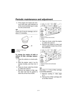 74
74 75
75 76
76 77
77 78
78 79
79 80
80 81
81 82
82 83
83 84
84 85
85 86
86 87
87 88
88 89
89 90
90 91
91 92
92 93
93 94
94 95
95 96
96 97
97 98
98 99
99 100
100 101
101 102
102 103
103 104
104 105
105 106
106 107
107 108
108 109
109 110
110 111
111 112
112 113
113 114
114 115
115 116
116 117
117 118
118 119
119

EAU49475
Adjustin g the ri der seat he")

