2017 SUBARU FORESTER Battery
[x] Cancel search: BatteryPage 416 of 634
Charge the battery.
.After the engine starts, the engine
speed will be kept high until the engine
has warmed up sufficiently.
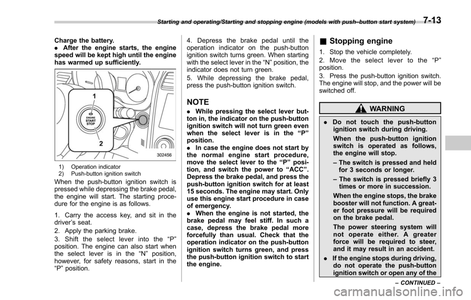
1) Operation indicator
2) Push-button ignition switch
When the push-button ignition switch is
pressed while depressing the brake pedal,
the engine will start. The starting proce-
dure for the engine is as follows.
1. Carry the access key, and sit in the
driver ’s seat.
2. Apply the parking brake.
3. Shift the select lever into the “P ”
position. The engine can also start when
the select lever is in the “N”position,
however, for safety reasons, start in the
“P ”position. 4. Depress the brake pedal until the
operation indicator on the push-button
ignition switch turns green. When starting
with the select lever in the
“N”position, the
indicator does not turn green.
5. While depressing the brake pedal,
press the push-button ignition switch.
NOTE
. While pressing the select lever but-
ton in, the indicator on the push-button
ignition switch will not turn green even
when the select lever is in the “P”
position.
. In case the engine does not start by
the normal engine start procedure,
move the select lever to the “P”posi-
tion, and switch the power to “ACC ”.
Depress the brake pedal, and press the
push-button ignition switch for at least
15 seconds. The engine may start. Only
use this engine start procedure in case
of emergency.
. When the engine is not started, the
brake pedal may feel stiff. In such a
case, depress the brake pedal more
forcefully than usual. Check that the
operation indicator on the push-button
ignition switch turns green, and press
the push-button ignition switch to start
the engine.
& Stopping engine
1. Stop the vehicle completely.
2. Move the select lever to the “P ”
position.
3. Press the push-button ignition switch.
The engine will stop, and the power will be
switched off.
WARNING
. Do not touch the push-button
ignition switch during driving.
When the push-button ignition
switch is operated as follows,
the engine will stop.
– The switch is pressed and held
for 3 seconds or longer.
– The switch is pressed briefly 3
times or more in succession.
When the engine stops, the brake
booster will not function. A great-
er foot pressure will be required
on the brake pedal.
The power steering system will
not operate either. A greater
force will be required to steer,
and it may result in an accident.
. If the engine stops during driving,
do not operate the push-button
ignition switch or open any of the
Starting and operating/Starting and stopping engine (models with push –button start system)
–CONTINUED –7-13
Page 417 of 634
Starting and operating/Remote engine start system (dealer option)
doors until the vehicle is stopped
in a safe location. It is dangerous
because the steering lock may be
activated. Stop the vehicle in a
safe location, and contact a
SUBARU dealer immediately.
CAUTION
.Do not stop the engine while the
select lever is in a position other
than the “P ” position.
. If the engine is stopped while the
select lever is in a position other
than the “P ” position, the power
will be in “ACC ”. If the vehicle is
left in this condition, the battery
may be discharged.
NOTE
Although you can stop the engine by
operating the push-button ignition
switch, do not stop the engine during
driving except in an emergency.
& When access key does not
operate properly
Refer to “Access key –if access key does
not operate properly ”F 9-17.
Remote engine start system
(dealer option)
WARNING
. There are some general precau-
tions when starting the engine.
Carefully read the precautions
described in “General precau-
tions when starting engine ”F 7-
9.
. Do not remote start a vehicle in
an enclosed environment (e.g.
closed garage). Prolonged opera-
tion of a motor vehicle in an
enclosed environment can cause
a harmful build-up of Carbon
Monoxide. Carbon Monoxide is
harmful to your health. Exposure
to high levels of Carbon Monox-
ide can cause headaches, dizzi-
ness or in extreme cases uncon-
sciousness and/or death.
. Before performing any servicing
of the vehicle, temporarily place
the remote engine start system in
service mode to prevent the
system from unexpectedly start-
ing the engine.
The remote engine start system allows you to start the engine from outside the
vehicle. In addition, the remote engine
start system can activate the heater or air
conditioner, providing you with a comfor-
table cabin upon entry.&
Models with “keyless access
with push-button start sys-
tem”
NOTE
For more details, refer to the Owner ’s
Manual supplement for the remote
engine start system.
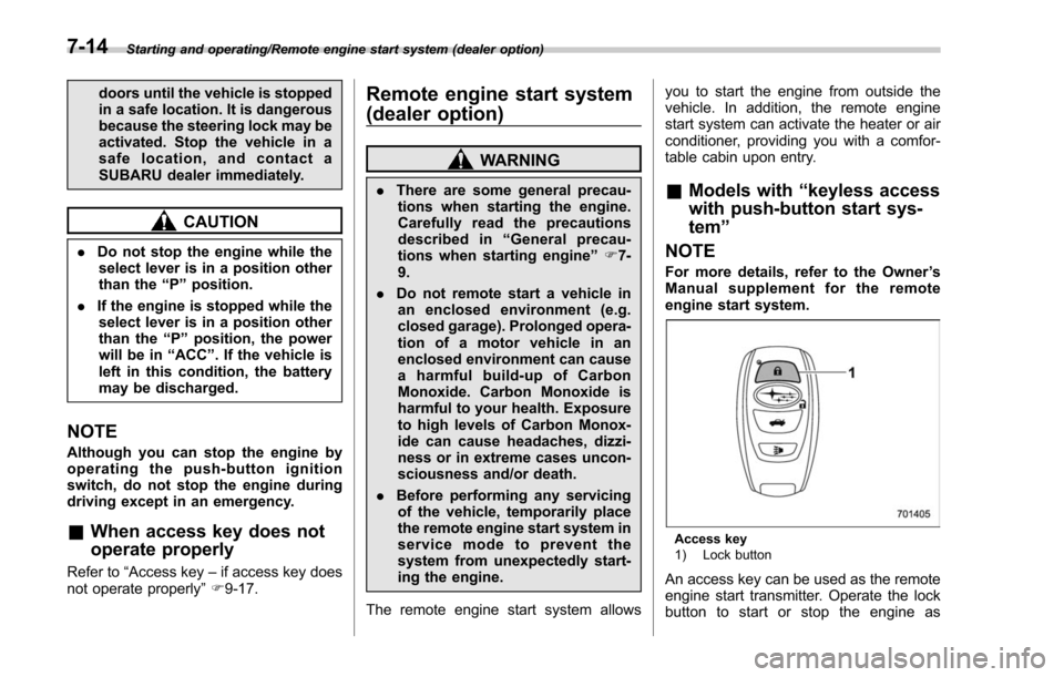
Access key
1) Lock button
An access key can be used as the remote
engine start transmitter. Operate the lock
button to start or stop the engine as
7-14
Page 423 of 634
Starting and operating/Remote engine start system (dealer option)
&Remote transmitter program
(models without “keyless ac-
cess with push-button start
system ”)
New transmitters can be programmed to
the remote engine start system in the
event that a transmitter is lost, stolen,
damaged or additional transmitters are
desired (the system will accept up to eight
transmitters). New remote engine start
transmitters can be programmed accord-
ing to the following procedure.
1. Open the driver ’s door (the driver ’s
door must remain opened throughout the
entire process).
2. Depress and hold the brake pedal.
3. Turn the ignition switch to “ON”then
“LOCK” , back to “ON”then “LOCK ”, back
to “ON ”then “LOCK”, then back to “ON”
again and leave the ignition “ON”through-
out the programming process.
4. The system will flash the side marker
lights, tail lights and parking lights and
honk the horn three times, indicating that
the system has entered the transmitter
learn mode.
5. Press and release the “
”button on
the transmitter that you want to program.
6. The system will flash the side marker
lights, tail lights and parking lights and honk the horn one time, indicating that the
system has learned the transmitter. Upon
successful programming, the remote start
confirmation transmitter button will flash
one time.
7. Repeat step 5 for any additional
transmitters (the system will accept up to
eight transmitters).
8. The system will exit the transmitter
learn mode if the key is turned to the
“LOCK”
position, the door is closed or
after 2 minutes.
& System maintenance
NOTE
For models without “keyless access
with push-button start system ”:
In the event that the vehicle ’s battery is
replaced, discharged or disconnected,
it will be necessary to start the vehicle
a minimum of one time using the key
prior to activating the remote engine
start system. This is required to allow
the vehicle electronic systems to re-
synchronize. !
Changing the battery
CAUTION
.Do not let dust, oil or water get on
or in the remote engine start
transmitter when replacing the
battery.
. Be careful not to damage the
printed circuit board in the re-
mote engine start transmitter
when replacing the battery.
. Be careful not to allow children to
touch the battery and any re-
moved parts; children could
swallow them.
. There is a danger of explosion if
an incorrect replacement battery
is used. Replace only with the
same or equivalent type of bat-
tery.
. Batteries should not be exposed
to excessive heat such as sun-
shine, fire or the like.
For models with “keyless access with
push-button start system ”:
Perform the procedure described in “Re-
placing battery of access key ”F 11-45.
7-20
Page 424 of 634
For models without“keyless access
with push-button start system ”:
The 3-volt lithium battery (model CR-
2032) supplied in your remote engine start
transmitter should last approximately one
year, depending on usage. When the
battery begins to weaken, you will notice
a decrease in range (distance from the
vehicle that your remote control operates).
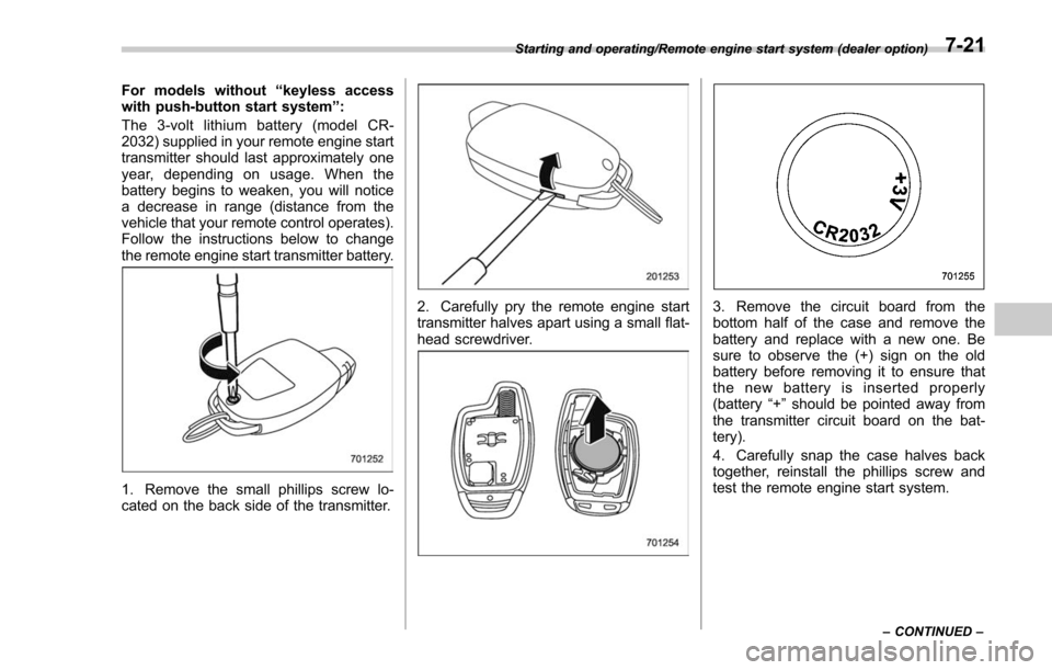
Follow the instructions below to change
the remote engine start transmitter battery.
1. Remove the small phillips screw lo-
cated on the back side of the transmitter.
2. Carefully pry the remote engine start
transmitter halves apart using a small flat-
head screwdriver.3. Remove the circuit board from the
bottom half of the case and remove the
battery and replace with a new one. Be
sure to observe the (+) sign on the old
battery before removing it to ensure that
the new battery is inserted properly
(battery “+”should be pointed away from
the transmitter circuit board on the bat-
tery).
4. Carefully snap the case halves back
together, reinstall the phillips screw and
test the remote engine start system.
Starting and operating/Remote engine start system (dealer option)
–CONTINUED –7-21
Page 428 of 634
.Never move the vehicle rearward
by inertia with the select lever set
in a forward driving position or
move the vehicle forward by
inertia with the select lever set
in the “R ” position. Doing so may
result in an unexpected accident
or malfunction.
. Avoid shifting from one of the
forward driving positions into the
“ R ” position or vice versa until
the vehicle has completely
stopped. Such shifting may
cause damage to the transmis-
sion.
. When parking the vehicle, first
securely apply the parking brake
and then place the select lever in
the “P ” position. Avoid parking
for a long time with the select
lever in any other position as
doing so could result in a dead
battery.
NOTE
. When the engine coolant tempera-
ture is still low, the transmission will
upshift or downshift at higher engine
speeds than when the coolant tempera-
ture is sufficiently high in order to
shorten the warm-up time and improve driveability. The gearshift timing will
automatically shift to the normal timing
after the engine has warmed up.
.
Immediately after transmission fluid
is replaced, you may feel that the
transmission operation is somewhat
unusual. This results from invalidation
of data which the on-board computer
has collected and stored in memory to
allow the transmission to shift at the
most appropriate times for the current
condition of your vehicle. Optimized
shifting will be restored as the vehicle
continues to be driven for a while.
. When driving a CVT model under
continuous heavy load conditions such
as when towing a camper or climbing a
long, steep hill, the engine speed or the
vehicle speed may automatically be
reduced. This is not a malfunction. This
phenomenon results from the engine
control function maintaining the cool-
ing performance of the vehicle. The
engine and vehicle speed will return to
a normal speed when the engine is able
to maintain the optimum cooling per-
formance after the heavy load de-
creases. Driving under a heavy load
must be performed with extreme care.
Do not try to pass a vehicle in front
when driving on an uphill slope while
towing. .
The continuously variable transmis-
sion is a chain type system that
provides superior transmission effi-
ciency for maximum fuel economy. At
times, depending on varying driving
conditions, a chain operating noise
may be heard that is characteristic of
this type of system.
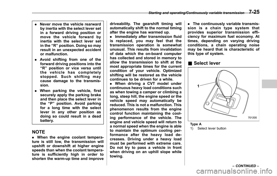
& Select lever
Type A
1) Select lever button
Starting and operating/Continuously variable transmission
–CONTINUED –
7-25
Page 463 of 634

Starting and operating/BSD/RCTA
1) The detection range of the radar sensors
2) The out of detection range of the radarsensors
B) Vehicle that may not be detected
WARNING
The approaching vehicle (B) may
not be detected because the vehicle
reversing is blocked by a parked
vehicle. Always be sure to check the
surroundings with your eyes when
reversing the vehicle, because the
detectability of RCTA is limited.
& System operation
! Operating conditions
The BSD/RCTA will operate when all of
the following conditions are met.
. The ignition switch is in the “ON ”
position.
. The BSD/RCTA warning indicator and
BSD/RCTA OFF indicator are turned off.
. The vehicle is driven at speeds above
6 mph (10 km/h) (except when reversing).
. The shift lever/select lever is in the “R”
position (RCTA only).
The BSD/RCTA will not operate in the
following situations.
. The BSD/RCTA OFF indicator is on.
. The vehicle speed is below 6 mph (10
km/h) even when the BSD/RCTA OFF
indicator remains off (except when rever-
sing).
NOTE
. In the following case, the BSD/RCTA
will stop operating and the BSD/RCTA
warning indicator will appear. If the
BSD/RCTA warning indicator appears,
have your vehicle inspected at a
SUBARU dealer as soon as possible.
–When a malfunction occurs in the
system, including the BSD/RCTA
approach indicator light .
In the following cases, the BSD/
RCTA will temporarily stop operating
(or may stop operating) and the BSD/
RCTA warning indicator will appear.
–When the radar sensor becomes
significantly misaligned (If the or-
ientation of the radar sensor is
shifted for any reason, readjust-
ment is required. Have the sensor
adjusted at a SUBARU dealer.)
– When a large amount of snow or
ice sticks to the rear bumper sur-
face around the radar sensors
– When the vehicle is driven on a
snow-covered road or in an envir-
onment in which there are no
objects around (such as in a desert)
for a long time
– When the temperature around
the radar sensors increased exces-
sively due to long driving on uphill
grades in summer, etc.
– When the temperature around
the radar sensors becomes extre-
mely low
– When the vehicle battery voltage
lowers
– When the vehicle battery be-
comes overvoltage
When the above conditions are cor-
rected, the BSD/RCTA will resume
7-60
Page 466 of 634

.The BSD/RCTA approach indicator
light may illuminate when driving close to
solid objects on the road or road side
(such as guardrails, tunnels and side-
walls).
. The BSD/RCTA approach indicator
light may flash when turning at an inter-
section in urban areas or a multilane
intersection.
. The BSD/RCTA approach indicator
light may flash and the warning buzzer
may sound if a building or a wall exists in
the reversing direction.
. In the following cases, the system may
detect a vehicle driving two lanes away
from your vehicle.
–When you are driving on the near
side of its lane from the corresponding
vehicle –
When the vehicle driving two lanes
away is driving on the near side of its
lane from your vehicle
& BSD/RCTA warning indicator
! System temporary stop indicator
System temporary stop indicator
This indicator appears when the system is
used under the following conditions.
.Extremely high or low temperatures
. When abnormal voltage exists for the
vehicle battery
. When the radar sensor is significantly
misaligned
Once the above conditions are corrected,
the system will recover from the temporary
stop condition and the indicator will disappear. If the indicator remains dis-
played for a prolonged time, have the
system inspected at a SUBARU dealer.
!
System temporary stop indicator
due to reduced radar sensitivity
System temporary stop indicator due to
reduced radar sensitivity
This indicator appears when the detect-
ability of the radar sensors is reduced.
Once the condition is corrected, the
system will recover from the temporary
stop condition and the indicator will
disappear. If the indicator remains dis-
played for a prolonged time, have the
system inspected at a SUBARU dealer.
Starting and operating/BSD/RCTA
–CONTINUED –7-63
Page 468 of 634

vehicle
–When using a chassis dynam-
ometer or free roller device, etc.
– When running the engine and
makingthewheelsrotatewhile
lifting up the vehicle
. If the ignition switch is turned to the
“ LOCK ”/“ OFF ”position, the last known
status of the system is maintained. For
example, if the ignition switch is turned
to the “LOCK ”/“ OFF ”position with the
BSD/RCTA deactivated, the BSD/RCTA
will remain deactivated the next time
the ignition switch is turned to the
“ ON ”position.
. If the vehicle battery is disconnected
due to situations such as battery
terminal or fuse replacement, after the
battery is reconnected, the BSD/RCTA
will be activated.
& Certification for the BSD/
RCTA
. U.S.-spec. models
FCC ID: OAYSRR2A
CAUTION
FCC WARNING
Changes or modifications not ex-
pressly approved by the party re- sponsible for compliance could void
the user
’s authority to operate the
equipment.
This device complies with part 15 of the
FCC Rules. Operation is subject to the
following two conditions: (1) This device
may not cause harmful interference, and
(2) this device must accept any interfer-
ence received, including interference that
may cause undesired operation.
. Canada-spec. models
This device complies with Industry
Canada licence-exempt RSS standard
(s). Operation is subject to the following
two conditions: (1) this device may not
cause interference, and (2) this device
must accept any interference, including
interference that may cause undesired
operation of the device.
Le présent appareil est conforme aux
CNR d ’Industrie Canada applicables aux
appareils radio exempts de licence. L ’ex-
ploitation est autorisée aux deux condi-
tions suivantes: (1) l ’appareil ne doit pas
produire de brouillage, et (2) l ’utilisateur
de l ’appareil doit accepter tout brouillage
radioélectrique subi, même si le brouillage
est susceptible d ’en compromettre le
fonctionnement.
& Handling of radar sensors
Radar sensors
The radar sensors, one on each side of
the vehicle, are mounted inside the rear
bumper.
Starting and operating/BSD/RCTA
–CONTINUED –7-65