2017 SUBARU FORESTER Battery
[x] Cancel search: BatteryPage 162 of 634
position.
The trip meter shows the distance that the
vehicle has been driven since you last set
it to zero.
If you press the trip knob when the ignition
switch is in the“LOCK”/ “OFF”or “ACC ”
position, the odometer/trip meter will light
up. It is possible to switch between the A
trip meter and B trip meter indications
while the odometer/trip meter is lit up. If
you do not press the trip knob within 10
seconds of illumination of the odometer/
trip meter, the odometer/trip meter will turn
off.
Also, if you open and close the driver ’s
door within 10 seconds of illumination of
the odometer/trip meter, the odometer/trip
meter will turn off.
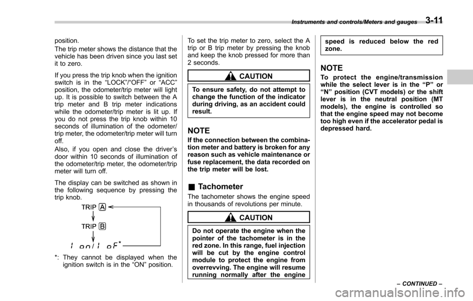
The display can be switched as shown in
the following sequence by pressing the
trip knob.
*: They cannot be displayed when the ignition switch is in the “ON ”position. To set the trip meter to zero, select the A
trip or B trip meter by pressing the knob
and keep the knob pressed for more than
2 seconds.
CAUTION
To ensure safety, do not attempt to
change the function of the indicator
during driving, as an accident could
result.
NOTE
If the connection between the combina-
tion meter and battery is broken for any
reason such as vehicle maintenance or
fuse replacement, the data recorded on
the trip meter will be lost.
&
Tachometer
The tachometer shows the engine speed
in thousands of revolutions per minute.
CAUTION
Do not operate the engine when the
pointer of the tachometer is in the
red zone. In this range, fuel injection
will be cut by the engine control
module to protect the engine from
overrevving. The engine will resume
running normally after the engine speed is reduced below the red
zone.
NOTE
To protect the engine/transmission
while the select lever is in the
“P ” or
“ N ” position (CVT models) or the shift
lever is in the neutral position (MT
models), the engine is controlled so
that the engine speed may not become
too high even if the accelerator pedal is
depressed hard.
Instruments and controls/Meters and gauges
–CONTINUED –3-11
Page 172 of 634

&ABS warning light
CAUTION
.If any of the following conditions
occur, we recommend that you
have the ABS repaired at the first
available opportunity by your
SUBARU dealer.
– The warning light does not
illuminate when the ignition
switch is turned to the “ON ”
position.
– The warning light illuminates
when the ignition switch is
turned to the “ON ”position,
but it does not turn off even
when the vehicle speed ex-
ceeds approximately 25 mph
(40 km/h).
– The warning light illuminates
during driving.
. When the warning light is on (and
the brake system warning light is
off), the ABS function shuts
down. However, the conventional
brake system continues to oper-
ate normally.
The ABS warning light illuminates to-
gether with the brake system warning light if the EBD system malfunctions. For
further details of the EBD system mal-
function warning, refer to
“Electronic
Brake Force Distribution (EBD) system
warning ”F 3-22.
NOTE
If the warning light behavior is as
described in the following conditions,
the ABS may be considered normal.
. The warning light illuminates when
the ignition switch is turned to the
“ ON ”position and turns off approxi-
mately 2 seconds after the engine has
started.
. The warning light illuminates right
after the engine is started but turns off
immediately, remaining off.
. The warning light remains illumi-
nated after the engine has been started,
but it turns off when the vehicle speed
reaches approximately 25 mph (40
km/h).
. The warning light illuminates during
driving, but it turns off immediately and
remains off.
When driving with an insufficient battery
voltage such as when the engine is jump
started, the ABS warning light may illumi-
nate. This is due to the low battery voltage
and does not indicate a malfunction.
When the battery becomes fully charged, the light will turn off.
&Brake system
warning light
The light illuminates with the parking
brake applied while the ignition switch is
in the
“ON”position. It turns off when the
parking brake is fully released.
WARNING
. Driving with the brake system
warning light on is dangerous.
This indicates your brake system
may not be working properly. If
the light remains illuminated,
have the brakes inspected by a
SUBARU dealer immediately.
. If at all in doubt about whether
the brakes are operating prop-
erly, do not drive the vehicle.
Have your vehicle towed to the
nearest SUBARU dealer for re-
pair.
The brake system warning light has the
following functions.
! Brake fluid level warning
This light illuminates when the brake fluid
level has dropped to near the “MIN”level
of the brake fluid reservoir with the ignition
Instruments and controls/Warning and indicator lights
–CONTINUED –3-21
Page 180 of 634

Inside warningchime Outside warning
chime Access key
warning light on
meter Operation indica-
tor on push-button
ignition switch Status Action
Long beep
(continuous) —— — Select lever position warning:
The engine is turned off by press-
ing the push-button ignition switch
and the select lever is in a position
other than the
“P ”position. Start the engine, shift the select
lever to the
“P ”position, switch the
push-button ignition switch to “OFF ”
and exit the vehicle.
Long beep
(continuous) —— — Select lever position warning:
The driver
’s door was opened while
the push-button ignition switch is in
a position other than “OFF ”and the
select lever is in a position other
than the “P ”position. Shift the select lever to the
“P ”
position, switch the push-button
ignition switch to “OFF ”and exit the
vehicle.
Ding —— — The battery of the access key is
low.Replace the battery of the access
key.
Ding —— Flashes in green
(15 seconds max.) Steering lock warning:
The engine start procedure was
performed, but the steering is still
locked. While turning the steering wheel
right and left lightly, depress the
brake pedal and press the push-
button ignition switch.
Ding —— Flashes in orangeSystem malfunction warning:
A malfunction was detected in the
power system or steering lock. Contact a SUBARU dealer imme-
diately and have the vehicle in-
spected.
NOTEAn electronic chirp will sound while the select lever is in the
“R ” position. In this case, the select lever position warning chime
will not sound.
Instruments and controls/Warning and indicator lights
–CONTINUED –3-29
Page 189 of 634
Instruments and controls/Information display (Mexico–spec. models)
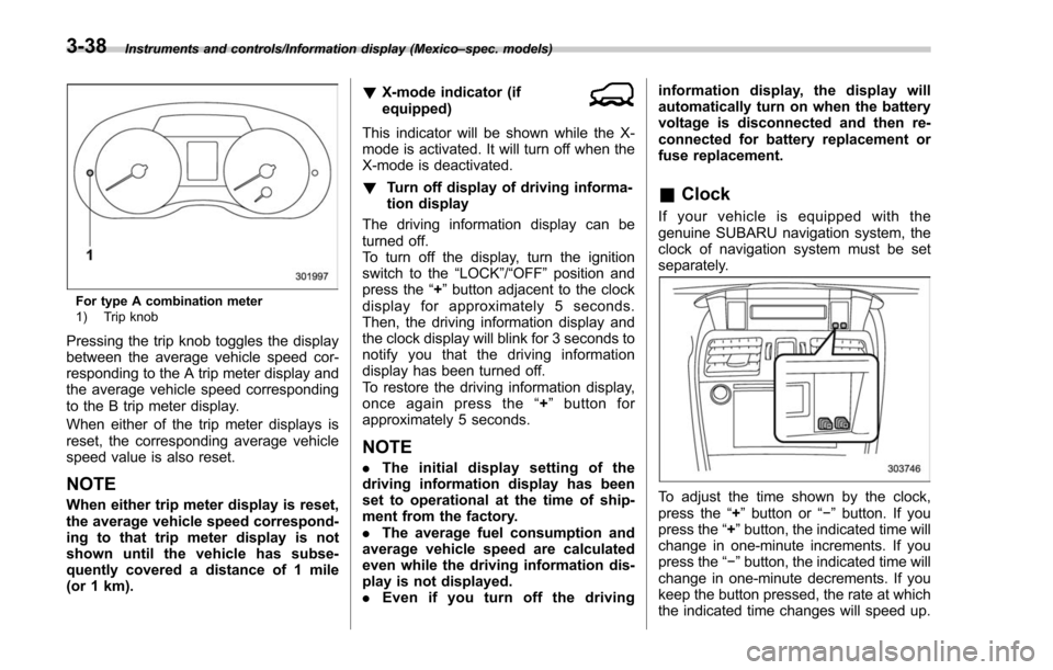
For type A combination meter
1) Trip knob
Pressing the trip knob toggles the display
between the average vehicle speed cor-
responding to the A trip meter display and
the average vehicle speed corresponding
to the B trip meter display.
When either of the trip meter displays is
reset, the corresponding average vehicle
speed value is also reset.
NOTE
When either trip meter display is reset,
the average vehicle speed correspond-
ing to that trip meter display is not
shown until the vehicle has subse-
quently covered a distance of 1 mile
(or 1 km). !
X-mode indicator (if
equipped)
This indicator will be shown while the X-
mode is activated. It will turn off when the
X-mode is deactivated.
! Turn off display of driving informa-
tion display
The driving information display can be
turned off.
To turn off the display, turn the ignition
switch to the “LOCK”/“OFF”position and
press the “+”button adjacent to the clock
display for approximately 5 seconds.
Then, the driving information display and
the clock display will blink for 3 seconds to
notify you that the driving information
display has been turned off.
To restore the driving information display,
once again press the “+ ” button for
approximately 5 seconds.
NOTE
. The initial display setting of the
driving information display has been
set to operational at the time of ship-
ment from the factory.
. The average fuel consumption and
average vehicle speed are calculated
even while the driving information dis-
play is not displayed.
. Even if you turn off the driving information display, the display will
automatically turn on when the battery
voltage is disconnected and then re-
connected for battery replacement or
fuse replacement.
&
Clock
If your vehicle is equipped with the
genuine SUBARU navigation system, the
clock of navigation system must be set
separately.
To adjust the time shown by the clock,
press the “+”button or “− ” button. If you
press the “+ ”button, the indicated time will
change in one-minute increments. If you
press the “− ”button, the indicated time will
change in one-minute decrements. If you
keep the button pressed, the rate at which
the indicated time changes will speed up.
3-38
Page 201 of 634
Instruments and controls/Multi function display
NOTE
The driving range on the remaining fuel
is calculated using the average fuel
consumption of the last 19 miles (30
km) driven. This value may be different
from the values calculated using the
average fuel consumption correspond-
ing to the driving distance of each trip
meter or the current fuel consumption.!Clock
The clock can be displayed in either 12-
hour display or 24-hour display. For details
about the setting, refer to “Current date
and time setting ”F 3-59.
NOTE
If the vehicle battery is disconnected,
the clock shown in the information bar
will be reset. Set the time again after
the vehicle battery is connected. For
details about the setting, refer to “To p
display setting ”F 3-68. !
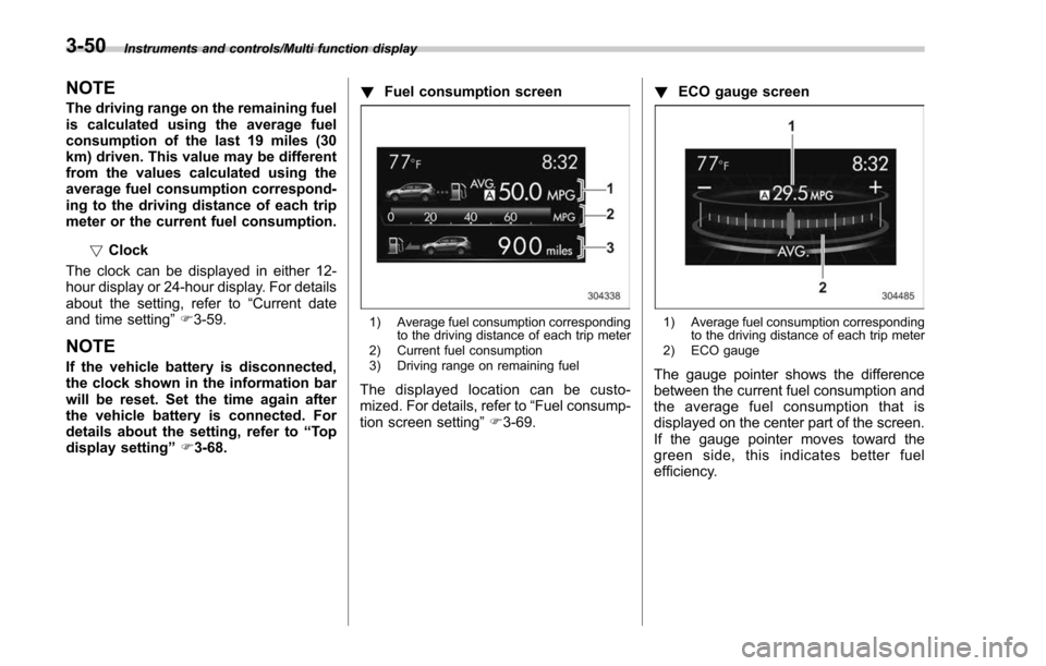
Fuel consumption screen
1) Average fuel consumption corresponding
to the driving distance of each trip meter
2) Current fuel consumption
3) Driving range on remaining fuel
The displayed location can be custo-
mized. For details, refer to “Fuel consump-
tion screen setting ”F 3-69. !
ECO gauge screen
1) Average fuel consumption corresponding
to the driving distance of each trip meter
2) ECO gauge
The gauge pointer shows the difference
between the current fuel consumption and
the average fuel consumption that is
displayed on the center part of the screen.
If the gauge pointer moves toward the
green side, this indicates better fuel
efficiency.
3-50
Page 244 of 634
Light control switch
CAUTION
.Use of any lights for a long period
of time while the engine is not
running can cause the battery to
discharge.
. Before leaving the vehicle, make
sure that the lights are turned off.
If the vehicle is left unattended
for a long time with the lights
illuminated, the battery may be
discharged.
Models with “keyless access with
push-button start system ”:
The light control switch operates when the
push-button ignition switch is in the “ACC”
or “ON ”position.
Regardless of the position of the light
control switch, the illuminated lights are
turned off when the push-button ignition
switch is turned off.
Models without “keyless access with
push-button start system ”:
The light control switch operates when the
key is inserted in the ignition switch.
Regardless of the position of the light
control switch, the illuminated lights are turned off when the key is removed from
the ignition switch.
NOTE
The light control switch can be oper-
ated (except auto on/off headlights),
even under the following conditions.
.
when the key is not inserted into the
ignition switch (models without “key-
less access with push-button start
system ”)
. when the push-button ignition
switch is turned off (models with “key-
less access with push-button start
system ”)
If the driver ’s door is opened while the
headlights are illuminated under such
conditions, the chirp sound will inform
the driver that the lights are illumi-
nated.
& Headlights
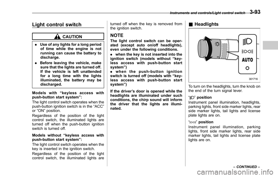
To turn on the headlights, turn the knob on
the end of the turn signal lever.
“
”position
Instrument panel illumination, headlights,
parking lights, front side marker lights, rear
side marker lights, tail lights and license
plate lights are on.
“
” position
Instrument panel illumination, parking
lights, front side marker lights, rear side
marker lights, tail lights and license plate
lights are on.
Instruments and controls/Light control switch
–CONTINUED –3-93
Page 261 of 634
Instruments and controls/Mirrors
until a“C”appears in the display. Once a
“C ”appears in the display, slowly drive the
vehicle in circles until compass is cali-
brated.
! HomeLink
®Wireless Control Sys-
tem
The HomeLink
®Wireless Control System
provides a convenient way to replace up
to three hand-held radio-frequency re-
motes used to activate devices such as
gate operators, garage door openers,
entry door locks, security systems, even
home lighting. The below steps are
generic programming instructions; for
Genie and Sommer garage door openers
please go directly to the HomeLink web-
site. Additional information and program-
ming videos can be found at
www.HomeLink.com and
www.youtube.com/HomeLinkGentex.
CAUTION
. Before programming HomeLink
to a garage door opener or gate
operator, make sure that people
and objects are out of the way of
the device to prevent potential
harm or damage.
. When programming a garage
door opener, it is advised to park outside of the garage.
. Do not use HomeLink with any
garage door opener that lacks
safety stop and reverse features
as required by U.S. federal safety
standards (this includes any gar-
age door opener model manufac-
tured before April 1, 1982). A
garage door that cannot detect
an object signaling the door to
stop and reverse does not meet
current U.S. federal safety stan-
dards.
. It is also recommended that a
new battery be placed in the
hand-held remote (garage door
opener remote) of the device for
quicker and more accurate train-
ing.
. Some vehicles may require the
ignition switch to be turned to the
“ON ”or “ACC ”position for pro-
gramming and/or operation of
HomeLink.
. Keep the hand-held remote (gar-
age door opener remote) of the
device you are programming for
use in other vehicles as well as
for future HomeLink program-
ming. It is also suggested that
upon the sale of the vehicle, the programmed HomeLink buttons
be erased for security purposes.
Refer to
“Erasing HomeLink But-
tons ”F 3-113.
! Programming a New HomeLink
Button
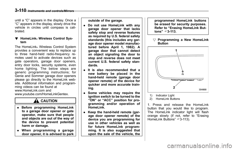
1) Indicator Light
2) HomeLink Buttons
1. Press and release the HomeLink
button that you would like to program.
The HomeLink indicator light will flash
orange slowly (if not, refer to “Erasing
HomeLink Buttons ”F 3-113).
3-110
Page 268 of 634
located on the climate control panel. The
rear window defogger, outside mirror
defogger and windshield wiper deicer are
activated simultaneously. The indicator
light on the control switch illuminates while
the defogger and deicer system is acti-
vated.
To turn them off, press the control switch
again. They also turn off when the ignition
switch is turned to the“ACC”or “LOCK” /
“ OFF ”position.
The defogger and deicer system will
automatically shut off after approximately
15 minutes. If the rear window and the
outside mirrors have been cleared and the
windshield wiper blades have been deiced
completely before that time, press the
control switch to turn them off. If defrost-
ing, defogging or deicing is not complete,
you have to press the control switch to
turn them on again.
For models with the automatic climate
control system (type B, C and D), it is
possible for the defogger and deicer
system to be set to continuous operation
mode by a SUBARU dealer. Consult your
SUBARU dealer for details. Also, for
models with a multi function display, the
setting can be changed using the display.
For details, refer to “Multi function display ”
F 3-44. If the battery voltage drops below the
permissible level, continuous operation of
the defogger and deicer system is can-
celed and the system stops operating.
CAUTION
.
To prevent the battery from being
discharged, do not operate the
defogger and deicer system con-
tinuously for any longer than
necessary.
. Do not use sharp instruments or
window cleaner containing abra-
sives to clean the inner surface
of the rear window. They may
damage the conductors printed
on the window.
NOTE
. Turn on the defogger and deicer
system if the wipers are frozen to the
windshield.
. If the windshield is covered with
snow, remove the snow so that the
windshield wiper deicer works effec-
tively.
. While the defogger and deicer sys-
tem is in the continuous operation
mode, if the vehicle speed remains at
9 mph (15 km/h) or lower for 15
minutes, the windshield wiper deicer automatically stops operating, though
the rear window defogger and outside
mirror defogger maintain continuous
operation in this condition.
.
While the defogger and deicer sys-
tem is in the continuous operation
mode, if the battery voltage drops
below the permissible level, continu-
ous operation of the defogger and
deicer system is canceled and the
system stops operating.
Instruments and controls/Defogger and deicer3-117