2017 RENAULT ALASKAN lock
[x] Cancel search: lockPage 9 of 340

1.
Bonnet (P. 3-17)
2. Windscreen wipers and washers
—S
witch operation (P. 2-34)
—W iper blade replacement (P. 8-16)
—W indow washer fluid (P. 8-11)
3. Sunroof*1 (P. 2-42)
4. Windows (P. 2-36) 5.
Roof rail*1 (P. 2-41)
6. Child safety rear door locks*1 (P. 3-5)
7. Doors
—K
eys (P. 3-2)
—D oor locks (P. 3-4)
—R emote keyless entry system*1 (P. 3-6)
—R emote Control Key system*1 (P. 3-7)
—S ecurity system*1 (P. 3-15) 8.
Outside rearview mirrors (P. 3-25)
9. Side turn signal lights
—B
ulb replacement (P. 8-23)
10. Tyres
—T
yres and wheels (P. 8-26)
—F lat tyre (P. 6-2)
—S pecifications (P. 9-4)
—F our-Wheel Drive (4WD)*1 (P. 5-32)
11. Headlights and turn signal lights
—S
witch operation (P. 2-31)
—B ulb replacement (P. 8-21)
12. Headlight cleaner*1
—O
peration (P. 2-35)
13. Front fog lights*1 or Daytime running lights*1
—S
witch operation (P. 2-33, P. 2-31)
—B ulb replacement (P. 8-23)
14. Towing eye*2 (P. 6-13)
*1: where fitted
*2: The layout illustrated is for the Right-Hand
Drive (RHD) model. On the Left-Hand Drive
(LHD) model, the towing eye is located on the
opposite side. NIC3080
EXTERIOR FRONT
Illustrated table of contents0-3
Page 11 of 340

1.
Inside rearview mirror (P. 3-23)
2. Sunglasses holder* (P. 2-40)
3. Microphone*
—B
luetooth® Hands-Free Phone System*
(P. 4-59, P. 4-65)
4. Sunroof switch* (P. 2-42)
5. Map lights (P. 2-43) 6.
Sun visors (P. 2-41)
7. Room light* (P. 2-44)
8. Rear personal light* (P. 2-45)
9. Console box* (P. 2-40)
—P
ower outlet (P. 2-38)
10. Cup holders* (P. 2-40) 11.
Door armrest
—P
ower window controls* (P. 2-36)
—P ower door lock switch (driver’s door)*
(P. 3-4)
—O utside rearview mirror remote control
switch (driver’s door)* (P. 3-25)
*: where fitted NIC2792
PASSENGER COMPARTMENT
Illustrated table of contents0-5
Page 14 of 340

LEFT-HAND DRIVE (LHD) MODEL
1. Meters and gauges (P. 2-2)
—V ehicle information display (P. 2-14)
2. Push-button ignition switch (models with
Remote Control Key system) (P. 5-15)
3. Audio system* (P. 4-31) or Navigation
system** —R
eversing camera* (P. 4-7)
—3 60° Camera* (P. 4-11)
4. Power outlet (P. 2-38)
5. Hazard warning flasher switch (P. 6-2)
6. Centre vent (P. 4-20)
7. Front passenger’s supplemental front-impact
air bag* (P. 1-29) 8.
Glove box (P. 2-39)
9. Heater and air conditioner control (P. 4-21)
10. USB (Universal Serial Bus) connection port
(P. 4-35)/iPod connection port (P. 4-45)
—A
uxiliary (AUX) input jack (P. 4-36)
11. Power door lock switch* (P. 3-4)
12. Hill descent control switch* (P. 5-38)
13. Parking brake
—O
peration (P. 3-26)
—C heck (P. 8-9)
14. Differential lock mode switch* (P. 5-32)
15. Four-Wheel Drive (4WD) mode switch*
(P. 5-26)
16. Ignition switch (models without Remote
Control Key system) (P. 5-14)
17. Steering wheel
—H
orn (P. 2-36)
—D river’s supplemental front-impact air bag*
(P. 1-29)
—P ower steering system (P. 5-49)
18. Fuel filler lid release (P. 3-18)
19. Bonnet release handle (P. 3-17)
j A: 4WD models
j B: 2WD models
*: where fitted
**: See the separate Navigation System Owner’s
Manual (where fitted). NIC3091
INSTRUMENT PANEL
0-8 Illustrated table of contents
Page 15 of 340

RIGHT-HAND DRIVE (RHD) MODEL
1. Front passenger’s supplemental front-impact
air bag* (P. 1-29)
2. Centre vent (P. 4-20)
3. Hazard warning flasher switch (P. 6-2)
4. Power outlet (P. 2-38) 5.
Audio system* (P. 4-31) or Navigation
system**
—R
eversing camera* (P. 4-7)
—3 60° Camera* (P. 4-11)
6. Push-button ignition switch (models with
Remote Control Key system) (P. 5-15)
7. Meters and gauges (P. 2-2)
—V
ehicle information display (P. 2-14) 8.
Bonnet release handle (P. 3-17)
9. Ignition switch (models without Remote
Control Key system) (P. 5-14)
10. Steering wheel
—H
orn (P. 2-36)
—D river’s supplemental front-impact air bag*
(P. 1-29)
—P ower steering system (P. 5-49)
11. USB (Universal Serial Bus) connection port
(P. 4-35)/iPod connection port (P. 4-45)
—A
uxiliary (AUX) input jack (P. 4-36)
12. Parking brake
—O
peration (P. 3-26)
—C heck (P. 8-9)
13. Power door lock switch (P. 3-4)
14. Hill descent control switch* (P. 5-38)
15. Differential lock mode switch* (P. 5-32)
16. Four-Wheel Drive (4WD) mode switch*
(P. 5-26)
17. Heater and air conditioner control (P. 4-21)
18. Glove box (P. 2-39)
—F
use box (P. 8-19)
j A: 4WD models
j B: 2WD models
*: where fitted
**: See the separate Navigation System Owner’s
Manual (where fitted). NIC3092
Illustrated table of contents
0-9
Page 20 of 340

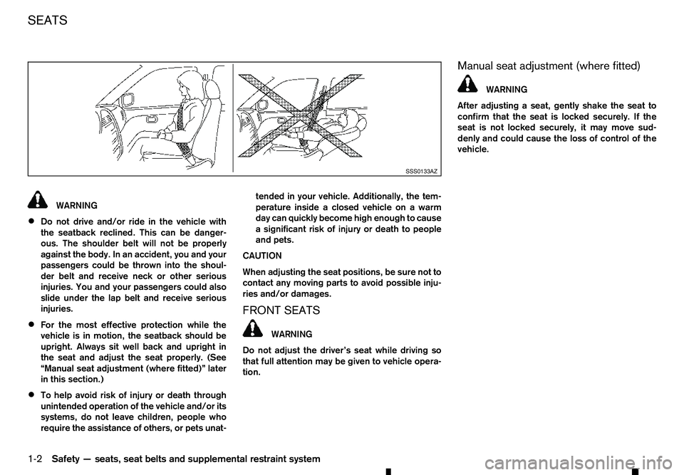
WARNING
• Do not drive and/or ride in the vehicle with
the seatback reclined. This can be danger-
ous. The shoulder belt will not be properly
against the body. In an accident, you and your
passengers could be thrown into the shoul-
der belt and receive neck or other serious
injuries. You and your passengers could also
slide under the lap belt and receive serious
injuries.
• For the most effective protection while the
vehicle is in motion, the seatback should be
upright. Always sit well back and upright in
the seat and adjust the seat properly. (See
“Manual seat adjustment (where fitted)” later
in this section.)
• To help avoid risk of injury or death through
unintended operation of the vehicle and/or its
systems, do not leave children, people who
require the assistance of others, or pets unat- tended in your vehicle. Additionally, the tem-
perature inside
aclosed vehicle on awarm
day can quickly become high enough to cause
as ignificant risk of injury or death to people
and pets.
CAUTION
When adjusting the seat positions, be sure not to
contact any moving parts to avoid possible inju-
ries and/or damages.
FRONT SEATS WARNING
Do not adjust the driver’s seat while driving so
that full attention may be given to vehicle opera-
tion. Manual seat adjustment (where fitted) WARNING
After adjusting
aseat, gently shake the seat to
confirm that the seat is locked securely. If the
seat is not locked securely, it may move sud-
denly and could cause the loss of control of the
vehicle. SSS0133AZ
SEATS
1-2
Safety —seats, seat belts and supplemental restraint system
Page 21 of 340

Forward and backward:
1. Pull up the adjusting lever ➀.
2. Slide the seat to the desired position.
3. Release the adjusting lever to lock the seat in position.
Reclining:
CAUTION
When moving the seats forward or backward, or
returning arear-reclined seatback to its upright
position, make sure you hold onto the seatback
while operating. If the seatback is not held, the
seat or seatback will move suddenly and could
cause injury.
1. Pull up the adjusting lever ➁.
2. Tilt the seatback to the desired position.
3. Release the adjusting lever to lock the seatback in position. The reclining feature allows the adjustment of the
seatback for occupants of different sizes to help
obtain the proper seat belt fit. (See “Fastening seat
belts” later in this section.)
The seatback may be reclined to allow occupants to
rest when the vehicle is parked.
Seat lifter (where fitted):
Pull up or push down the adjusting lever ➂to ad-
just the seat height until the desired position is
achieved.
Power seat adjustment (where fitted) WARNING
Never leave children or adults who would nor-
mally require the support of others alone in the
vehicle. Pets should not be left alone either. They
could unknowingly activate switches or controls,
or move the vehicle, and inadvertently become
involved in aserious accident and injure them-
selves. Operating tips:
• The power seat motor has an auto-reset over-
load protection circuit. If the motor stops during
the seat adjustment, wait 30 seconds, then reac-
tivate the switch.
• To avoid discharge of the battery, do not operate
the power seats for
along period of time when
the engine is not running. JVR0392XZ
Safety —seats, seat belts and supplemental restraint system
1-3
Page 24 of 340

WARNING
• Never allow anyone to ride on the rear seats
when they are in the fold-up position. Use of
this area by passengers without proper re-
straints could result in serious injury or death
in an accident or sudden stop.
• When folding or returning the rear seat, be
careful not to squeeze your finger between
the seat cushion and the body side.
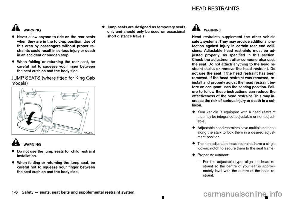
JUMP SEATS (where fitted for King Cab
models) WARNING
• Do not use the jump seats for child restraint
installation.
• When folding or returning the jump seat, be
careful not to squeeze your finger between
the seat cushion and the body side. •
Jump seats are designed as temporary seats
only and should only be used on occasional
short distance travels. WARNING
Head restraints supplement the other vehicle
safety systems. They may provide additional pro-
tection against injury in certain rear end colli-
sions. Adjustable head restraints must be ad-
justed properly, as specified in this section. Check the adjustment after someone else uses
the seat. Do not attach anything to the head re-
straint stalks or remove the head restraint. Do
not use the seat if the head restraint has been
removed. If the head restraint was removed, re-
install and properly adjust the head restraint be-
fore an occupant uses the seating position. Fail-
ure to follow these instructions can reduce the
effectiveness of the head restraint. This may in-
crease the risk of serious injury or death in acol-
lision.
• Your vehicle is equipped with
ahead restraint
that may be integrated, adjustable or non-adjust-
able.
• Adjustable head restraints have multiple notches
along the stalk to lock them in
adesired adjust-
ment position.
• The non-adjustable head restraints have
asingle
locking notch to secure them to the seat frame.
• Proper Adjustment:
–F
or the adjustable type, align the head re-
straint so the centre of your ear is approxi-
mately level with the centre of the head re-
straint. NIC2817 HEAD RESTRAINTS
1-6 Safety —seats, seat belts and supplemental restraint system
Page 25 of 340

–I
fyour ear position is still higher than the rec-
ommended alignment, place the head
restraint at the highest position.
• If the head restraint has been removed, ensure
that it is reinstalled and locked in place before
riding in that designated seating position.
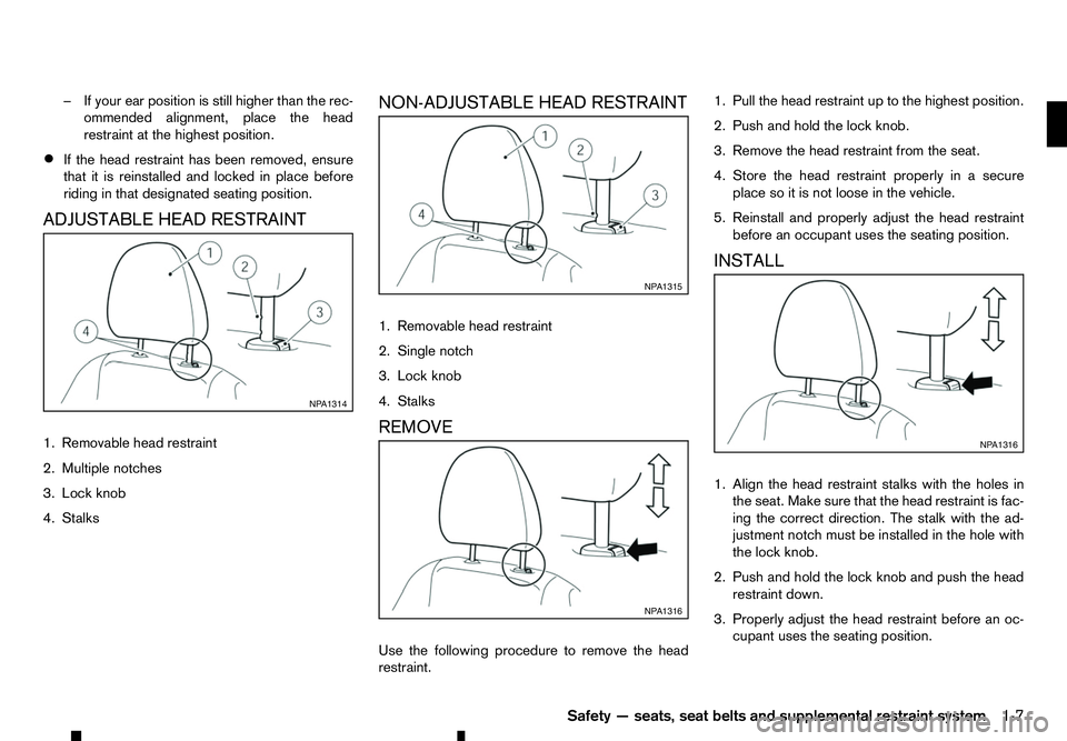
ADJUSTABLE HEAD RESTRAINT
1. Removable head restraint
2. Multiple notches
3. Lock knob
4. Stalks NON-ADJUSTABLE HEAD RESTRAINT
1. Removable head restraint
2. Single notch
3. Lock knob
4. Stalks
REMOVE
Use the following procedure to remove the head
restraint. 1. Pull the head restraint up to the highest position.
2. Push and hold the lock knob.
3. Remove the head restraint from the seat.
4. Store the head restraint properly in
asecure
place so it is not loose in the vehicle.
5. Reinstall and properly adjust the head restraint before an occupant uses the seating position.
INSTALL
1. Align the head restraint stalks with the holes in the seat. Make sure that the head restraint is fac-
ing the correct direction. The stalk with the ad-
justment notch must be installed in the hole with
the lock knob.
2. Push and hold the lock knob and push the head restraint down.
3. Properly adjust the head restraint before an oc- cupant uses the seating position. NP A1314 NP A1315
NP A1316 NP A1316
Safety —seats, seat belts and supplemental restraint system 1-7