2017 RENAULT ALASKAN ECU
[x] Cancel search: ECUPage 120 of 340

How to activate system (where fitted)
1. Close all windows.
The system can be armed even if the windows
are open.
2. Place the ignition switch in the OFF position.
3. Carry the integrated key fob or the Remote Con- trol Key with you and get out of the vehicle.
4. Close and lock all doors. The doors can be locked with the integrated key fob, the Remote
Control Key, door handle request switch (where
fitted), power door lock switch or mechanical
key.
5. Confirm that the security indicator light comes on. The security indicator light glows for about
30 seconds and then blinks. The system is now
activated. If, during this 30 second time period,
the door is unlocked or the ignition switch is
placed in the ACC or ON position, the system
will not activate.
Even when the driver and/or passengers are in
the vehicle, the system will activate with all doors
locked with the ignition switch in the LOCK posi-
tion. When pushing the ignition switch to the ACC
or ON position, the system will be released.
Theft warning system operation
The vehicle security system will give the following
alarm:
• The hazard indicator blinks and the horn sounds
intermittently. •
The alarm automatically turns off after approxi-
mately 30 seconds. However, the alarm reacti-
vates if the vehicle is tampered with again.
The alarm is activated by:
• Unlocking the door without using the integrated
key fob, the Remote Control Key, the door handle
request switch (where fitted) or the mechanical
key. (Even if the door is opened by releasing the
door inside lock knob, the alarm will activate.)
How to stop alarm
• The alarm will stop only by unlocking
adoor by
pushing the UNLOCK button on the Remote
Control Key.
• The alarm will not stop if the ignition switch is
placed in the ACC or ON position.
ANTI-THEFT SYSTEM (ATS)
The Anti-Theft System (ATS) will not allow the en-
gine to start without the use of the registered ATS
key.
If the engine does not start using the registered ATS
key, it may be due to interference caused by:
• Another ATS key.
• Automated toll road device.
• Automated payment device.
• Other devices that transmit similar signals. Start the engine using the following procedure:
1. Remove any items that may be causing the inter-
ference away from the ATS key.
2. Leave the ignition switch in the ON position for approximately 5seconds.
3. Place the ignition switch in the OFF or LOCK position, and wait approximately 10 seconds.
4. Repeat steps 2and 3again.
5. Start the engine.
6. Repeat the steps above until all possible interfer- ences are eliminated.
If this procedure allows the engine to start,
RENAULT recommends placing the registered ATS
key separate from other devices to avoid interfer-
ence.
If ATS is malfunctioning, this light will remain on
while the ignition switch is in the ON position.
If the light remains on and/or the engine does
not start, contact an approved dealer or qualified
workshop for ATS service as soon as possible.
Be sure to bring all Remote Control Keys that you
have when visiting an approved dealer for ser-
vice.
3-16 Pre-driving checks and adjustments
Page 121 of 340

WARNING
• The bonnet must be closed and latched se-
curely before driving. Failure to do so could
cause the bonnet to fly open and result in an
accident.
• Never open the bonnet if steam or smoke is
coming from the engine compartment to
avoid injury.
OPENING BONNET
1. Pull the bonnet lock release handle➀located
below the instrument panel until the bonnet
springs up.
2. Locate the lever ➁in between the bonnet and
grille and push the lever with your fingertips.
3. Raise the bonnet.
4. Remove the support rod and insert it into the slot ➂.
Hold the coated parts j
Aw hen removing or re-
setting the support rod. Avoid direct contact with
the metal parts, as they may be hot immediately
after the engine has been stopped. CLOSING BONNET
1. While supporting the bonnet, return the support
rod to its original position.
2. Slowly lower the bonnet to about 20 to 30 cm (8 to 12 in) above the bonnet lock, then let it drop.
3. Make sure it is securely latched. NIC3101
BONNET
Pre-driving checks and adjustments
3-17
Page 122 of 340

WARNING
• Fuel is extremely flammable and highly explo-
sive under certain conditions. You could be
burned or seriously injured if it is misused or
mishandled. Always stop the engine and do
not smoke or allow open flames or sparks
near the vehicle when refuelling.
• Fuel may be under pressure. Turn the cap a
half of
aturn, and wait for any “hissing” sound
to stop to prevent fuel from spraying out and
possibly causing personal injury. Then remove
the cap.
• Use only an original equipment type fuel filler
cap as
areplacement. It has abuilt-in safety
valve needed for proper operation of the fuel
system and emission control system. An in-
correct cap can result in aserious malfunc-
tion and possible injury. OPENING FUEL FILLER LID
Fuel filler lid opener switch
To open the fuel filler lid, push the fuel filler lid opener
switch located on the lower side of the instrument
panel.
To lock the fuel filler lid, close the lid until it securely
locks. FUEL FILLER CAP
Type A
The fuel filler cap is
aratcheting type. Turn the cap
anticlockwise ➀to remove. Tighten the cap clock-
wise ➁until ratchet clicks, more than twice, after
refuelling.
Put the fuel filler cap on the cap holder j
Aw hile
refuelling.
CAUTION
If fuel is spilled on the vehicle body, flush it away
with water to avoid paint damage. NIC2736 JVP021 1XZ
FUEL FILLER LID AND CAP
3-18
Pre-driving checks and adjustments
Page 123 of 340

Type B
To open the fuel filler cap, turn the key anticlockwise
➀ .
Turn the fuel filler cap anticlockwise ➁after the
cap is unlocked. The fuel filler cap is
ascrew-on ratcheting type.
After refuelling, tighten the cap clockwise until more
than 2ratcheting clicks are heard. The fuel filler cap
locks automatically when it is tightened.
The AdBlue® filler lid➀is located on the right
hand side of the vehicle.
OPENING AdBlue® FILLER LID
To open the AdBlue® filler lid, push the AdBlue®
filler lid slightly and release.
To close the AdBlue® filler lid, close the lid until it
securely locks in place. JVP0370XZ NDI1684
NDI1646
AdBlue® FILLER LID AND CAP
Pre-driving checks and adjustments 3-19
Page 124 of 340

LOCKING AdBlue® FILLER LID
The AdBlue® filler lid is locked and unlocked using
the Keyless Entry System, see “Remote Control Key
system (where fitted)” earlier in this section for addi-
tional details.
AdBlue® FILLER CAP
The AdBlue® filler cap is anon-ratcheting type. Turn
the cap anticlockwise ➀to remove. Tighten the
cap clockwise ➁until tight.
CAUTION
If AdBlue® is spilled on the vehicle body, flush it
away with water to avoid paint damage. WARNING
• While driving, never allow anyone to ride in
the cargo area. Abrupt braking or stopping
could lead to personal injury or death.
• Do not drive the vehicle with the tailgate down.
• Properly secure all cargo with ropes or straps
to help prevent it from sliding or shifting. In a
sudden stop or collision, unsecured cargo
could cause personal injury.
TAILGATE
Locking or unlocking tailgate
(where fitted)
To lock the tailgate, insert the key to the tailgate key
cylinder and turn the key clockwise ➀.
To unlock the tailgate, turn the key anticlockwise ➁ . For Remote Control Key equipped models, see
“Mechanical key” earlier in this section for removing
the mechanical key.
Opening the tailgate
To open the tailgate, pull the tailgate handle ➀and
lower the tailgate. The support wires will hold the
gate open.
• The weight of the cargo load must be evenly dis-
tributed over both the front and the rear axles.
• All cargo should be securely fastened with ropes
or straps to prevent it from shifting or sliding
within the vehicle. WARNING
• Do not drive the vehicle with the tailgate down.
• While driving, never allow anyone to ride in
the cargo area. Abrupt braking or stopping
could lead to personal injury or death. NDI1647
SP A2696Z NP A1529
CARGO BED (where fitted)
3-20 Pre-driving checks and adjustments
Page 125 of 340

Closing the tailgate
When closing the tailgate, make sure that the latches
or levers are securely locked.
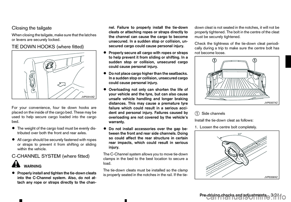
TIE DOWN HOOKS (where fitted)
For your convenience, four tie down hooks are
placed on the inside of the cargo bed. These may be
used to help secure cargo loaded into the cargo
bed.
• The weight of the cargo load must be evenly dis-
tributed over both the front and rear axles.
• All cargo should be securely fastened with ropes
or straps to prevent it from shifting or sliding
within the vehicle.
C-CHANNEL SYSTEM (where fitted) WARNING
• Properly install and tighten the tie-down cleats
into the C-Channel system. Also, do not at-
tach any rope or straps directly to the chan- nel. Failure to properly install the tie-down
cleats or attaching ropes or straps directly to
the channel can cause the cargo to become
unsecured. In
asudden stop or collision, un-
secured cargo could cause personal injury.
• Properly secure all cargo with ropes or straps
to help prevent it from sliding or shifting. In a
sudden stop or collision, unsecured cargo
could cause personal injury.
• Do not place cargo higher than the seatbacks.
In
as udden stop or collision, unsecured cargo
could cause personal injury.
• Overloading not only can shorten the life of
your vehicle and the tyre, but can also cause
unsafe vehicle handling and longer braking
distances. This may cause
apremature tyre
failure which could result in aserious acci-
dent and personal injury. Failures caused by
overloading are not covered by the vehicle’s
warranty.
• Do not install accessories over the gap be-
tween the front and rear side channels. Doing
so could affect the rear structure in certain
rear impacts, which could result in serious
injury.
The C-Channel system allows you to move tie-down
clamps in the bed to the best location to secure a
load.
The tie-down cleats must be installed so the clamp
is properly seated in the notches in the rail. If the tie- down cleat is not seated in the notches, it will not be
properly tightened. The bolt in the centre of the cleat
must be securely tightened.
Check the tightness of the tie-down cleat periodi-
cally during
atrip to make sure the centre bolt has
not become loose.
➀ Side channels
Install the tie-down cleat as follows:
1. Loosen the centre bolt completely. JVP0314XZ
JVP0357XZ
JVP0358XZ
Pre-driving checks and adjustments
3-21
Page 126 of 340

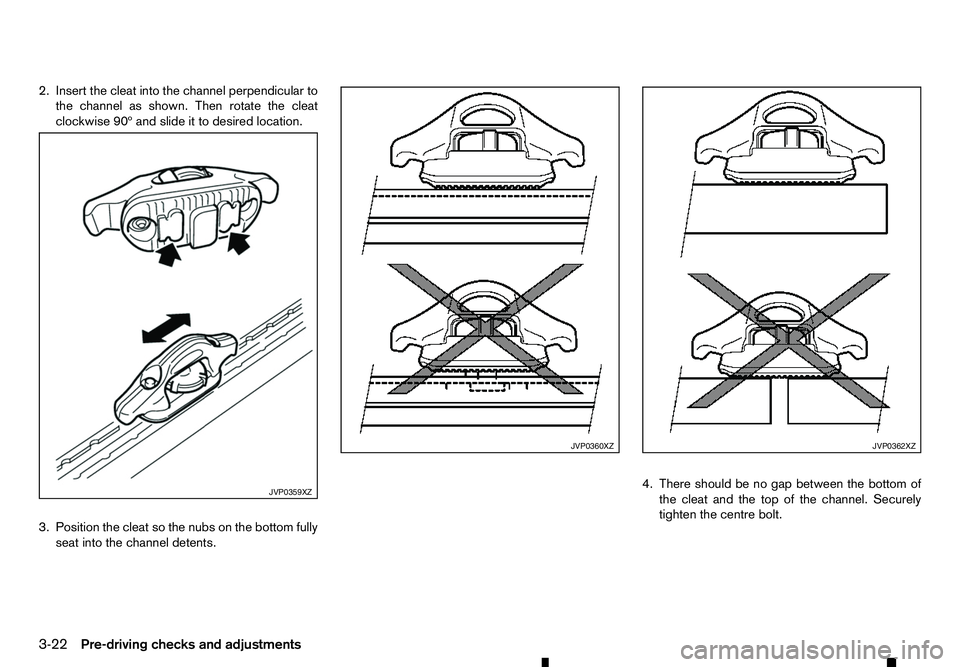
2. Insert the cleat into the channel perpendicular to
the channel as shown. Then rotate the cleat
clockwise 90º and slide it to desired location.
3. Position the cleat so the nubs on the bottom fully seat into the channel detents. 4. There should be no gap between the bottom of
the cleat and the top of the channel. Securely
tighten the centre bolt. JVP0359XZ JVP0360XZ JVP0362XZ
3-22 Pre-driving checks and adjustments
Page 139 of 340

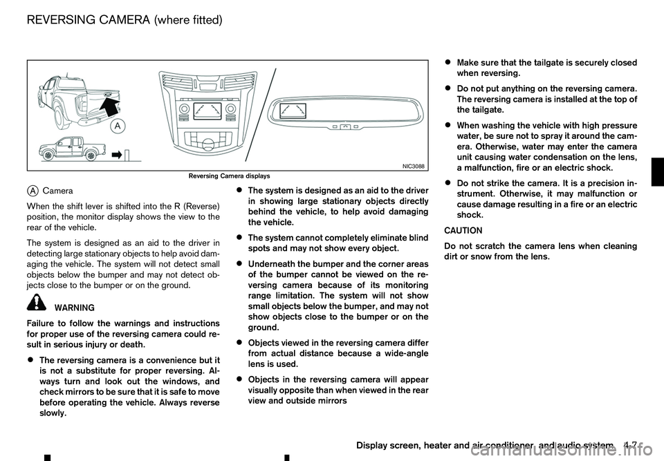
j
A Camera
When the shift lever is shifted into the
R(Reverse)
position, the monitor display shows the view to the
rear of the vehicle.
The system is designed as an aid to the driver in
detecting large stationary objects to help avoid dam-
aging the vehicle. The system will not detect small
objects below the bumper and may not detect ob-
jects close to the bumper or on the ground. WARNING
Failure to follow the warnings and instructions
for proper use of the reversing camera could re-
sult in serious injury or death.
• The reversing camera is
aconvenience but it
is not asubstitute for proper reversing. Al-
ways turn and look out the windows, and
check mirrors to be sure that it is safe to move
before operating the vehicle. Always reverse
slowly. •
The system is designed as an aid to the driver
in showing large stationary objects directly
behind the vehicle, to help avoid damaging
the vehicle.
• The system cannot completely eliminate blind
spots and may not show every object.
• Underneath the bumper and the corner areas
of the bumper cannot be viewed on the re-
versing camera because of its monitoring
range limitation. The system will not show
small objects below the bumper, and may not
show objects close to the bumper or on the
ground.
• Objects viewed in the reversing camera differ
from actual distance because
awide-angle
lens is used.
• Objects in the reversing camera will appear
visually opposite than when viewed in the rear
view and outside mirrors •
Make sure that the tailgate is securely closed
when reversing.
• Do not put anything on the reversing camera.
The reversing camera is installed at the top of
the tailgate.
• When washing the vehicle with high pressure
water, be sure not to spray it around the cam-
era. Otherwise, water may enter the camera
unit causing water condensation on the lens,
am
alfunction, fire or an electric shock.
• Do not strike the camera. It is
aprecision in-
strument. Otherwise, it may malfunction or
cause damage resulting in afire or an electric
shock.
CAUTION
Do not scratch the camera lens when cleaning
dirt or snow from the lens. NIC3088
Reversing Camera displays
REVERSING CAMERA (where fitted)
Display screen, heater and air conditioner, and audio system4-7