2017 PEUGEOT PARTNER TEPEE ELECTRIC tow
[x] Cancel search: towPage 136 of 252
98
ISOFIX mountings
Your vehicle has been approved in accordance with
the latest ISOFIX regulation.
The mountings comprise three rings for each seat:
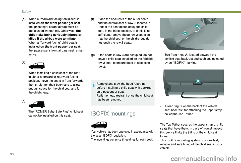
- Two front rings A, located between the
vehicle seat backrest and cushion, indicated
by an "ISOFIX" marking,
-
A r
ear ring B , on the back of the vehicle
seat backrest, for attaching the upper strap
called the Top Tether.
The Top Tether secures the upper strap of child
seats that have them. In case of frontal impact,
this device limits the tilting of the child seat
forward.
This ISOFIX mounting system provides fast,
reliable and safe fitting of the child seat in your
vehicle.
Remove and stow the head restraint
before installing a child seat with backrest
on a passenger seat.
Refit the head restraint once the child seat
has been removed.
(d)
When a "rear ward facing" child seat is
installed on the front passenger seat ,
the passenger's front airbag must be
deactivated without fail. Otherwise, the
child risks being seriously injured or
killed if the airbag were to inflate .
When a "for ward facing" child seat is
installed on the front passenger seat ,
the passenger's front airbag must remain
active.
(e)
When installing a child seat at the rear,
in either a for ward or rear ward facing
position, move the seats in front for wards,
then straighten their backrests to allow
enough space for the child seat and for
the child's legs.
(e)
The "RÖMER Baby-Safe Plus" child seat
cannot be installed on this seat. (f )
Place the backrests of the outer seats
and the central seat of row 2, located in
front of the seat occupied by the child
seat, in the table position, or if this is not
sufficient, remove these row 2 seats so
that the child seat or the child's legs do
not touch the row 2 seats.
(g) If the seats in row 3 are occupied, do not
leave a child seat installed on the foldable
row 2 seat, to ensure ease of access to
row 3.
Safety
Page 137 of 252
99
The ISOFIX child seats are fitted with two
latches which are secured on the two front
rings A.
Some also have an upper strap which is
attached to rear ring B .
To secure the child seat to the Top Tether:
-
r
emove and stow the head restraint before
installing a child seat on this seat (refit it
once the child seat has been removed),
-
r
un the strap of the child seat behind the top
of the seat backrest, centring it between the
holes for the head restraint rods,
-
f
ix the hook of the upper strap to rear ring B ,
-
t
ighten the upper strap.The incorrect installation of a child seat in
a vehicle compromises the protection of
the child in the event of an accident.
Strictly follow the fitting instructions
provided in the installation guide supplied
with the child seat.
For information on the possibilities for
installing ISOFIX child seats in your
vehicle, refer to the locations table.Recommended ISOFIX seat Locations of ISOFIX child seats
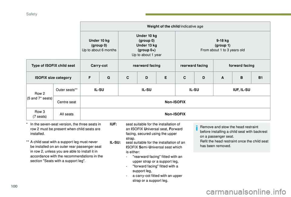
In line with European regulations, this table
indicates the options for installing ISOFIX child
seats on the vehicle seats fitted with ISOFIX
mountings.
In the case of the universal and semi-universal
ISOFIX child seats, the child seat's ISOFIX size
category, designated by a letter from A to G , is
indicated on the child seat next to the ISOFIX
logo.
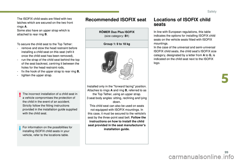
RÖMER Duo Plus ISOFIX
(size category: B1 )
Group 1: 9 to 18
kg
Installed only in the "forward facing" position. Attaches to rings A and ring B , referred to as
the Top Tether, using an upper strap.
3 seat body angles: sitting, reclining and lying down.
This child seat can also be used on seats not equipped with ISOFIX mountings. In
this case, it must be secured to the vehicle's
seat by the three-point seat belt. Follow the instructions on how to install the child
seat provided in the seat manufacturer's installation guide.
5
Safety
Page 138 of 252
100
Remove and stow the head restraint
before installing a child seat with backrest
on a passenger seat.
Refit the head restraint once the child seat
has been removed.
Weight of the child
/indicative age
Under 10
kg
(group 0)
Up to about 6
months
Under 10
kg
(group 0)
Under 13
kg
(group 0+)
Up to about 1 year 9 -18
kg
(g ro up 1)
From about 1 to 3 years old
Type of ISOFIX child seat Carr y- cotrearward facing rearward facing forward facing
ISOFIX size categor y F G C D E C D A B B1
Row 2
(5 and 7* seats) Outer seats**
IL- SU IL- SUIL- SUI U F, I L - S U
Centre seat Non-ISOFIX
Row 3
(7 seats) All seats
Non-ISOFIX
*
I
n the seven-seat version, the three seats in
row 2
must be present when child seats are
installed.
**
A c
hild seat with a support leg must never
be installed on an outer rear passenger seat
in row 2, unless you are able to install it in
accordance with the recommendations in the
section "Seats with a support leg". I UF:
seat suitable for the installation of
an ISOFIX U niversal seat, F or ward
facing, secured using the upper
strap.
IL- SU: seat suitable for the installation of an
ISOFIX S emi-Universal seat which
is either:
-
"
rear ward facing" fitted with an
upper strap or a support leg,
-
"
for ward facing" fitted with a
support leg,
-
a c
arry-cot fitted with an upper
strap or a support leg.
Safety
Page 141 of 252

103
Driving recommendations
Obser ve the Highway Code and remain vigilant
whatever the traffic conditions.
Pay close attention to the traffic and keep your
hands on the wheel so that you are ready to
react at any time to any eventuality.
As a safety measure, the driver should only
carry out any operations that require close
attention when the vehicle is stationary.
On a long journey, a break every two hours is
strongly recommended.
In bad weather, drive smoothly, anticipate the
need to brake and increase the safety distance.
Driving on flooded roads
We strongly advise against driving on flooded
roads, as this could cause serious damage
to the engine or gearbox, as well as to the
electrical systems of your vehicle.
Important!
Never drive with the parking brake applied
– risk of overheating and damage to the
braking system!
Do not park and do not run the engine
with the vehicle stationary, in areas where
substances and combustible materials
(dry grass, leaves, etc.) can come into
contact with the hot exhaust system – Risk
of fire!Never leave a vehicle unsuper vised with
the engine running. If you have to leave
your vehicle with the engine running, apply
the parking brake and put the gearbox into
neutral or position N or P
, depending on
the type of gearbox.
In case of towing
If you are obliged to drive through water:
- c heck that the depth of water does not
exceed 15
cm, taking account of waves that
might be generated by other users,
-
d
eactivate the Stop & Start function,
-
d
rive as slowly as possible without stalling.
Under no circumstances exceed 6
mph
(10
km/h),
-
d
o not stop and do not switch off the engine.
On leaving the flooded road, as soon as
circumstances allow, make several light brake
applications to dry the brake discs and pads.
If in doubt about the state of your vehicle,
contact a PEUGEOT dealer or a qualified
workshop. Driving with a trailer places greater
demands on the towing vehicle and
requires extra care from the driver.
Side wind
F Take into account the increased sensitivity
to wind.
Cooling
Towing a trailer on a slope increases the
temperature of the coolant.
As the fan is electrically controlled, its cooling
capacity is not dependent on the engine speed.
F
T
o lower the engine speed, reduce your
speed.
The maximum towable load on an incline
depends on the gradient and the exterior
temperature.
In all cases, keep a check on the coolant
temperature.
6
Driving
Page 142 of 252

104
In some cases of particularly demanding use
(when towing the maximum load on a steep
gradient in high temperatures), the engine
power is automatically limited. In such a case,
the air conditioning is automatically switched
off to increase the available engine power.F
I
f this warning lamp and the
STOP warning lamp come on,
stop the vehicle and switch off
the engine as soon as possible.
New vehicle
Do not pull a trailer before having driven at
least 620
miles (1,000 kilometres).
Braking
Towing a trailer increases the braking distance.
To avoid overheating of the brakes, the use of
engine braking is recommended.
Ty r e s
F Check the tyre pressures of the towing vehicle and of the trailer, observing the
recommended pressures.
Lighting
F Check the electrical lighting and signalling on the trailer and the headlamp beam height
of your vehicle. For more information on adjusting
the Headlamp beam
, refer to the
corresponding section.
The rear parking sensors will be
deactivated automatically to avoid the
audible signal if a genuine PEUGEOT
towbar is used.
Starting and stopping
Running and accessories position.
To unlock the steering, turn the steering wheel
gently while turning the key, without forcing. In
this position, certain accessories can be used. Starting position.
The starter is operated. the engine turns over,
release the key.
STOP position
: anti-theft.
The ignition is off. Turn the steering wheel until
the steering column locks. Remove the key.
If this warning lamp comes on, a door
or the bonnet is not closed correctly.
Please check!Diesel engines
If the temperature is high enough,
the warning lamp comes on for
less than a second, you can start
without waiting.
In cold weather, wait for this warning lamp to go
off then operate the starter (starting position)
until the engine starts.
When switching off the ignition, let the
engine run for a few seconds to allow the
turbocharger (Diesel engine) to return to
idle.
Do not press the accelerator when
switching off the ignition.
There is no need to engage a gear after
parking the vehicle.
Driving
Page 143 of 252

105
Electronic engine
immobiliser
All of the keys contain an electronic immobiliser
device.
This device locks the engine supply system.
It is activated automatically when the key is
removed from the ignition.
When the ignition switch is turned on, a
dialogue is set up between the key and the
electronic immobiliser.
The metal part of the key must be correctly
unfolded to ensure a good connection.
In case of lost keys
See a PEUGEOT dealer with the vehicle
registration certificate and your ID.
A PEUGEOT dealer can retrieve the key
code and the transponder code to order the
replacement key.
When you leave the vehicle, check that the
lamps are off and do not leave valuables
visible.
As a safety precaution (with children on
board), remove the key from the ignition when
leaving the vehicle, even for a short time.
Parking brake
Application
F Pull the parking brake lever up to immobilise your vehicle.
F
C
heck that the parking brake is applied
firmly before leaving the vehicle.
When parking on a slope, turn your
wheels towards the kerb and pull the
parking brake lever up.
There is no advantage in engaging a gear
after parking the vehicle, particularly if the
vehicle is loaded. Apply the parking brake only when the
vehicle is stationary
.
In the exceptional case of use of the
parking brake when the vehicle is moving,
apply the brake by pulling gently to avoid
locking the rear wheels (risk of skidding).
Release
F Pull the lever up slightly and press the button to release the parking brake lever.
When the vehicle is being driven, this
warning lamp coming on indicates
that the parking brake is still on or
has not been fully released.
Manual gearbox
To change gear easily, always press the clutch
pedal fully.
To prevent the mat from becoming caught
under the pedal:
-
e
nsure that the mat is positioned and
secured to the floor correctly,
-
n
ever fit one mat on top of another.
When driving, avoid leaving your hand on the
gear knob as the force exerted, even if slight,
may wear the internal components of the
gearbox over time.
6
Driving
Page 160 of 252
122
With monochrome screen C
F Press the MENU button for access to the
main menu.
F
Sel
ect "Personalisation-Configuration ".
F
Sel
ect "Define the vehicle parameters ".
F
Sel
ect "Driving assistance ".
F
Sel
ect "Automatic emergency braking :
OFF " or " Automatic emergency braking :
ON ".
F
P
ress the " 7" or " 8" button to tick or
untick the box and respectively activate or
deactivate the system.
F
P
ress the " 5" or " 6" button, then the OK
button to select the " OK" box and confirm or
the Back button to cancel.
With the touch screen
F Press the " MENU" button.
F Sel ect the " Driving" menu.
F
I
n the secondary page, select " Vehicle
parameters ".
F
Sel
ect the " Driving assistance " tab.
F
T
ick or untick the " Automatic emergency
braking " box to activate or deactivate the
system.
F
Confirm.
Operating faults
Sensor fault
The operation of the laser sensor may suffer
inter ference from accumulations of dirt or
misting of the windscreen. In this case you are
warned by the display of a message.
Use windscreen demisting and regularly clean
the area of the windscreen in front of the
sensor. Do not stick or other wise attach any object
on the windscreen in front of the sensor.
System fault
In the event of a malfunction of the system, you
are warned by an audible signal and the display
of the message " Automatic braking system
fault ".
Have the system checked by a PEUGEOT
dealer or a qualified workshop.
In the event of an impact to the
windscreen at the sensor, deactivate the
system and contact a PEUGEOT dealer
or a qualified workshop
to have your
windscreen replaced. Do not attempt to remove, adjust or test
the sensor.
Only a PEUGEOT dealer or a qualified
workshop is able to work on the system.
When towing a trailer or when the vehicle
is being towed, the system must be
deactivated.
Parking sensors
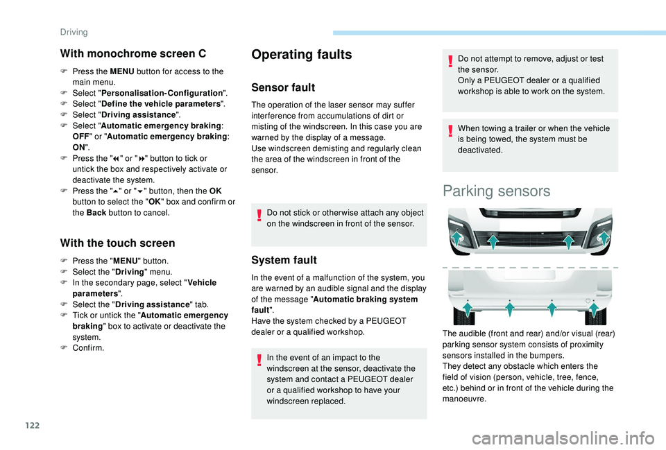
The audible (front and rear) and/or visual (rear)
parking sensor system consists of proximity
sensors installed in the bumpers.
They detect any obstacle which enters the
field of vision (person, vehicle, tree, fence,
etc.) behind or in front of the vehicle during the
manoeuvre.
Driving
Page 162 of 252
124
The system will be deactivated
automatically if a trailer is being towed or if
a bicycle carrier is fitted (vehicle fitted with
a towbar or bicycle carrier recommended
by PEUGEOT).
The parking sensor system cannot in
any circumstances replace the need for
vigilance on the part of the driver.
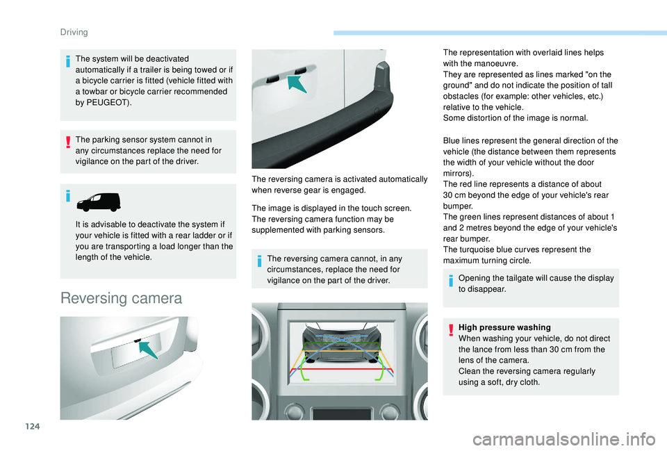
Reversing camera
The image is displayed in the touch screen.
The reversing camera function may be
supplemented with parking sensors.The reversing camera cannot, in any
circumstances, replace the need for
vigilance on the part of the driver. The representation with overlaid lines helps
with the manoeuvre.
They are represented as lines marked "on the
ground" and do not indicate the position of tall
obstacles (for example: other vehicles, etc.)
relative to the vehicle.
Some distortion of the image is normal.
Blue lines represent the general direction of the
vehicle (the distance between them represents
the width of your vehicle without the door
m i r r o r s).
The red line represents a distance of about
30
cm beyond the edge of your vehicle's rear
b u m p e r.
The green lines represent distances of about 1
and 2
metres beyond the edge of your vehicle's
rear bumper.
The turquoise blue cur ves represent the
maximum turning circle.
Opening the tailgate will cause the display
to disappear.
High pressure washing
When washing your vehicle, do not direct
the lance from less than 30
cm from the
lens of the camera.
Clean the reversing camera regularly
using a soft, dry cloth.
It is advisable to deactivate the system if
your vehicle is fitted with a rear ladder or if
you are transporting a load longer than the
length of the vehicle.
The reversing camera is activated automatically
when reverse gear is engaged.
Driving