2017 PEUGEOT PARTNER TEPEE ELECTRIC maintenance
[x] Cancel search: maintenancePage 3 of 252
1
.
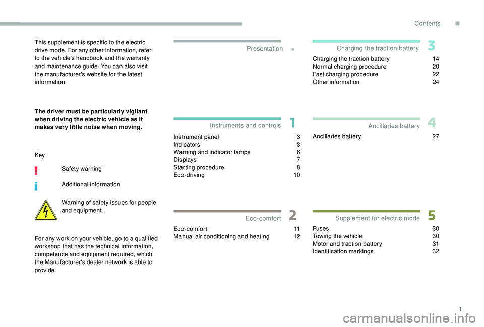
Instrument panel 3
I ndicators 3
Warning and indicator lamps
6
D
isplays
7
Starting procedure
8
E
co-driving
10
Eco-comfort
11
Manual air conditioning and heating
1
2Charging the traction battery
1
4
Normal charging procedure
2
0
Fast charging procedure
2
2
Other information
2
4
Ancillaries battery 2 7
Fuses
30
Towing the vehicle
3
0
Motor and traction battery
3
1
Identification markings
3
2
Presentation
Instruments and controls
Eco-comfort Charging the traction battery
Supplement for electric mode Ancillaries batteryThis supplement is specific to the electric
drive mode. For any other information, refer
to the vehicle's handbook and the warranty
and maintenance guide. You can also visit
the manufacturer's website for the latest
information.
The driver must be par ticularly vigilant
when driving the electric vehicle as it
makes ver y little noise when moving.
Key
Safety warning
Additional information
Warning of safety issues for people
and equipment.
For any work on your vehicle, go to a qualified
workshop that has the technical information,
competence and equipment required, which
the Manufacturer's dealer network is able to
provide.
Contents
.
Contents
Page 12 of 252
10
Eco-driving
Practical advice
Drive smoothly
The electrical consumption of your vehicle
depends very strongly on the route you take,
your style of driving and your speed.
In all cases, adopt a smooth driving style.
Recover energy
Driving with anticipation allows you to recover
energy and increase the range of the vehicle.
Limit the causes of excessive
energy consumption
As with any vehicle, limit the load being
carried and keep aerodynamic resistance to a
minimum (avoid windows open above 30 mph
(50 km/h), roof bars, roof box, etc.).
Excessive use of the air conditioning and
heating, particularly at low speeds, can reduce
the range of your vehicle considerably. For this
reason you should try to optimise their use.Obser ve the ser vicing and
maintenance recommendations
Check the tyre pressures regularly and
follow the schedule of ser vicing operations
recommended by the manufacturer.
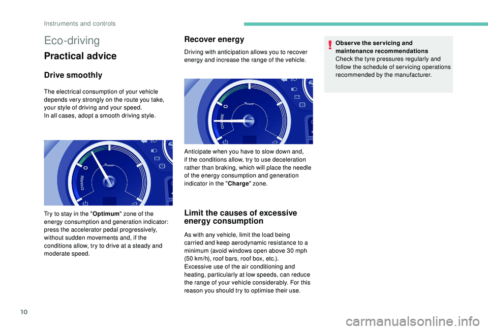
Try to stay in the " Optimum" zone of the
energy consumption and generation indicator:
press the accelerator pedal progressively,
without sudden movements and, if the
conditions allow, try to drive at a steady and
moderate speed. Anticipate when you have to slow down and,
if the conditions allow, try to use deceleration
rather than braking, which will place the needle
of the energy consumption and generation
indicator in the "
Charge" zone.
Instruments and controls
Page 39 of 252
Welcome
Thank you for choosing a Peugeot Partner.
This document presents the information and recommendations required
for you to be able to explore your vehicle in complete safety.
Your vehicle will be fitted with only some of the equipment described in
this document, depending on its trim level, version and the specification
for the country in which it was sold.
The descriptions and illustrations are given as indications only.
Automobiles PEUGEOT reser ves the right to modify the technical
specifications, equipment and accessories without having to update this
edition of the handbook.
If ownership of your vehicle is transferred, please ensure this Complete
Handbook is passed on to the new owner.
In this document you will find all of the instructions and
recommendations on use that will allow you to enjoy your vehicle to the
fullest. It is strongly recommended that you familiarise yourself with it
as well as the Warranty and Maintenance Record which will provide
you with information about the warranties, ser vicing and roadside
assistance associated with your vehicle. Key
Safety warning
Additional information
Contributes to the protection of the
environment
Left-hand drive vehicle
Right-hand drive vehicle
Key
This allows you to identify the special features of your vehicle: Partner Tepee passenger vehicle only
Partner commercial vehicle only
Page 44 of 252
6
Limit the causes of excess
consumption
Spread loads throughout the vehicle; place
the heaviest items in the bottom of the boot,
as close as possible to the rear seats.
Limit the loads carried in the vehicle and
reduce wind resistance (roof bars, roof rack,
bicycle carrier, trailer, etc.). Preferably, use a
roof box.
Remove roof bars and the roof rack after use.
At the end of winter, remove snow tyres and
refit your summer tyres.
Observe the recommendations
on maintenance
Check the tyre pressures regularly, when cold,
referring to the label in the door aperture,
driver's side.
Carry out this check in particular:
-
b
efore a long journey,
-
a
t each change of season,
-
a
fter a long period out of use.
Do not forget the spare wheel and the tyres on
any trailer or caravan. Have your vehicle ser viced regularly (engine
oil, oil filter, air filter, passenger compartment
filter, etc.) and obser ve the schedule of
operations in the manufacturer's service
schedule.
When filling the tank, do not continue after the
3
rd cut-off of the nozzle to avoid over flow.
At the wheel of your new vehicle, it is only
after the first 1,900
miles (3,000 kilometres)
that you will see the fuel consumption settle
down to a consistent average. With a BlueHDi Diesel engine, if the SCR
system is faulty, your vehicle becomes
polluting. Visit a PEUGEOT dealer or a
qualified workshop as soon as possible to
bring your vehicle’s nitrogen oxide emissions
back in line with the regulations.
Eco-driving
Page 55 of 252
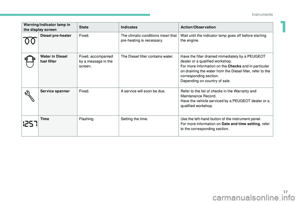
17
Diesel pre-heaterFixed. The climatic conditions mean that
pre-heating is necessary. Wait until the indicator lamp goes off before starting
the engine.
Water in Diesel
fuel filter Fixed, accompanied
by a message in the
screen. The Diesel filter contains water. Have the filter drained immediately by a PEUGEOT
dealer or a qualified workshop.
For more information on the Checks and in particular
on draining the water from the Diesel filter, refer to the
corresponding section.
Depending on country of sale.
Service spanner Fixed. A ser vice will soon be due. Refer to the list of checks in the Warranty and
Maintenance Record.
Have the vehicle ser viced by a PEUGEOT dealer or a
qualified workshop.
Time Flashing. Setting the time. Use the left-hand button of the instrument panel.
For more information on Date and time setting , refer
to the corresponding section.
Warning/indicator lamp in
the display screen
State
Indicates Action/Observation
1
Instruments
Page 107 of 252

69
Recommendations for ventilation and air conditioning
In order for these systems to be fully effective,
follow the operation and maintenance
guidelines below:
F
T
o ensure that the air is distributed evenly,
keep the external air intake grilles at the
base of the windscreen, the nozzles, the
vents, the air outlets and the air extractor
in the boot free from obstructions.
F
D
o not cover the sunshine sensor,
located on the dashboard; this is used for
regulation of the automatic air conditioning
system.
F
O
perate the air conditioning system for
at least 5 to 10
minutes once or twice a
month to keep it in per fect working order.
F
E
nsure that the passenger compartment
filter is in good condition and have the
filter elements replaced regularly. We
recommend the use of a combined
passenger compartment filter. Thanks to
its special active additive, it contributes
to the purification of the air breathed by
the occupants and the cleanliness of the
passenger compartment (reduction of
allergic symptoms, bad odours and greasy
deposits). If after an extended stop in sunshine, the
interior temperature is very high, first air
the passenger compartment for a few
moments.
Put the air flow control at a setting high
enough to quickly change the air in the
passenger compartment.
The condensation created by the air
conditioning results in a discharge of water
under the vehicle which is per fectly normal.
Depending on version and country
of sale, the air conditioning system
contains fluorinated greenhouse gas
R13 4A
.
Gas capacity: 0.450
kg (+/- 0.025 kg),
GWP index 1,430 t (equivalent CO
2:
0.6 4 4 t).
F
T
o ensure correct operation of the
air conditioning system, you are also
advised to have it checked regularly
as recommended in the Warranty and
Maintenance Record.
F
I
f the system does not produce cold air,
switch it off and contact a PEUGEOT
dealer or a qualified workshop.
When towing the maximum load on a steep
gradient in high temperatures, switching off
the air conditioning increases the available
engine power and so improves the towing
ability.
To avoid the windows misting up and
deterioration in the quality of the air:
-
d
o not drive for too long with the
ventilation switched off.
-
d
o not keep air recirculation set for an
extended period.
Stop & Star t
The heating and air conditioning systems
only work when the engine is running.
Temporarily deactivate the Stop &
Start system to maintain a comfortable
temperature in the passenger
compartment.
For more information on Stop & Star t,
refer to the corresponding section.
3
Ease of use and comfort
Page 171 of 252
133
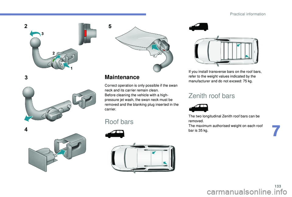
Maintenance
Correct operation is only possible if the swan
neck and its carrier remain clean.
Before cleaning the vehicle with a high-
pressure jet wash, the swan neck must be
removed and the blanking plug inserted in the
c a r r i e r.
Roof bars
If you install transverse bars on the roof bars,
refer to the weight values indicated by the
manufacturer and do not exceed: 75 kg.
Zenith roof bars
The two longitudinal Zenith roof bars can be
removed.
The maximum authorised weight on each roof
bar is 35
kg.
7
Practical information
Page 172 of 252
134
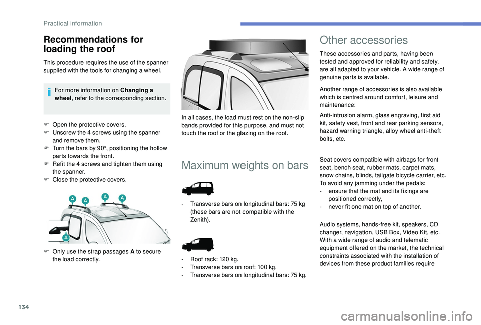
F Open the protective covers.
F U nscrew the 4 screws using the spanner
and remove them.
F
T
urn the bars by 90°, positioning the hollow
parts towards the front.
F
R
efit the 4 screws and tighten them using
the spanner.
F
C
lose the protective covers.
Maximum weights on bars
F Only use the strap passages A to secure the load correctly. In all cases, the load must rest on the non-slip
bands provided for this purpose, and must not
touch the roof or the glazing on the roof.
-
T
ransverse bars on longitudinal bars: 75 kg
(these bars are not compatible with the
Zenith).
-
R
oof rack: 120 kg.
-
T
ransverse bars on roof: 100 kg.
-
T
ransverse bars on longitudinal bars: 75
kg.
Other accessories
These accessories and parts, having been
tested and approved for reliability and safety,
are all adapted to your vehicle. A wide range of
genuine parts is available.
Another range of accessories is also available
which is centred around comfort, leisure and
maintenance:
Anti-intrusion alarm, glass engraving, first aid
kit, safety vest, front and rear parking sensors,
hazard warning triangle, alloy wheel anti-theft
bolts, etc.
Seat covers compatible with airbags for front
seat, bench seat, rubber mats, carpet mats,
snow chains, blinds, tailgate bicycle carrier, etc.
To avoid any jamming under the pedals:
-
e
nsure that the mat and its fixings are
positioned correctly,
-
n
ever fit one mat on top of another.
Recommendations for
loading the roof
This procedure requires the use of the spanner
supplied with the tools for changing a wheel.For more information on Changing a
wheel , refer to the corresponding section.
Audio systems, hands-free kit, speakers, CD
changer, navigation, USB Box, Video Kit, etc.
With a wide range of audio and telematic
equipment offered on the market, the technical
constraints associated with the installation of
devices from these product families require
Practical information