Page 252 of 404
250
Fitting the towball
F Below the rear bumper, remove the protective plug 2 from the towball carrier 1 .
F
I
nsert the end of towball 5 into carrier 1 and
push it upwards; the locking will take place
automatically. F
T
he locking wheel 6 turns a quarter of a
turn anti-clockwise; take care to keep your
hands clear!
F
C
heck that the mechanism has correctly
locked in to place (position A ).
F
C
lose the lock 7 using the key.F
A
lways remove the key. The key cannot be
removed when the lock is open.
F C lip the cap onto the lock.
F
R
emove the protective cover from the
towball.
F
A
ttach the trailer to the towball.
F
A
ttach the cable on the trailer to the safety
eye 4
on the carrier.
F
I
nsert the trailer plug and give it a quarter
turn to connect it to socket 3
of the carrier.
Practical information
Page 253 of 404
251
Removing the towball
F Give a quarter turn and pull the trailer plug to disconnect it from socket 3 of the carrier.
F
D
etach the cable on the trailer from the
safety eye 4
on the carrier.
F
D
etach the trailer from the towball.
F
R
efit the protective cover to the towball.
F
R
emove the cap from the lock and press it
onto the head of the key. F
I
nsert the key into the lock 7
.
F
O
pen the lock using the key.
F
H
old towball 5 firmly in one hand; using
the other hand, pull and turn locking wheel
6
fully in a clockwise direction; do not
release the locking wheel. F
E
xtract the towball from the bottom of its
carrier 1 .
F R elease the locking wheel; this
automatically stops in the unlocked position
(position B ).
F
R
efit protective plug 2 to carrier 1.
F
C
arefully stow the towball in its bag away
from knocks and dirt.
7
Practical information
Page 256 of 404
254
Snow chains
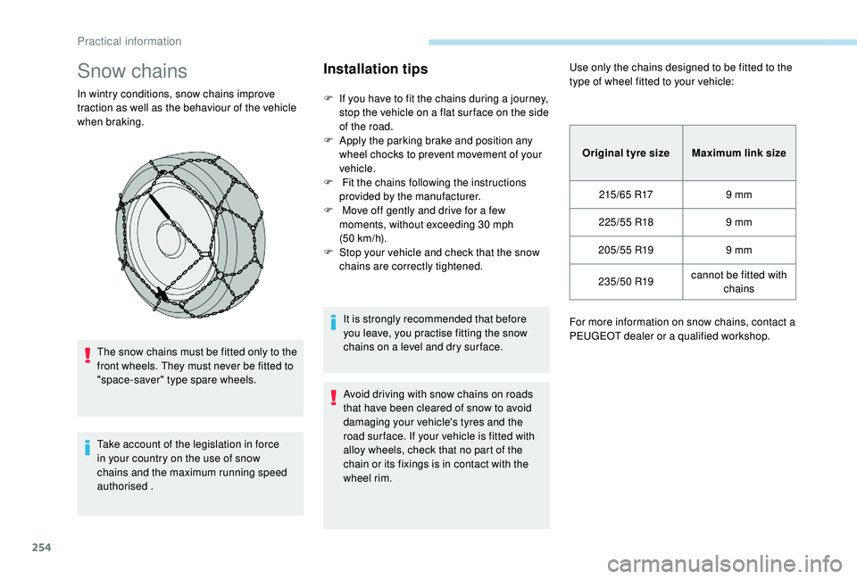
In wintry conditions, snow chains improve
traction as well as the behaviour of the vehicle
when braking.The snow chains must be fitted only to the
front wheels. They must never be fitted to
"space-saver" type spare wheels.
Take account of the legislation in force
in your country on the use of snow
chains and the maximum running speed
authorised .
Installation tips
F If you have to fit the chains during a journey, stop the vehicle on a flat sur face on the side
of the road.
F
A
pply the parking brake and position any
wheel chocks to prevent movement of your
vehicle.
F
F
it the chains following the instructions
provided by the manufacturer.
F
M
ove off gently and drive for a few
moments, without exceeding 30
mph
(50
km/h).
F
S
top your vehicle and check that the snow
chains are correctly tightened.
It is strongly recommended that before
you leave, you practise fitting the snow
chains on a level and dry sur face.
Avoid driving with snow chains on roads
that have been cleared of snow to avoid
damaging your vehicle's tyres and the
road sur face. If your vehicle is fitted with
alloy wheels, check that no part of the
chain or its fixings is in contact with the
wheel rim. Use only the chains designed to be fitted to the
type of wheel fitted to your vehicle:
Original tyre size Maximum link size
215/65
R179
mm
225/55
R189
mm
205/55
R199
mm
235/50
R19cannot be fitted with
chains
For more information on snow chains, contact a
PEUGEOT dealer or a qualified workshop.
Practical information
Page 269 of 404
267
Engine 2.0 HDi
F Fill the fuel tank with at least five litres of Diesel.
F
O
pen the bonnet.
F
I
f necessary, unclip the cover to access the
priming pump.
F
L
oosen the degassing bolt.
F
U
se the priming pump until fuel appears in
the transparent tube.
F
R
etighten the degassing bolt.
F
O
perate the starter until the engine starts (if
the engine does not start at the first attempt,
wait around 15
seconds before trying
again).
F
I
f the engine does not start after a few
attempts, operate the priming pump again
then start the engine.
F
P
ut it back in place, clip in the cover and
ensure it is clipped in.
F
C
lose the boot again.
Tool kit
This is a set of tools provided with the vehicle.
Its content depends on your vehicle's
equipment:
-
t
emporary puncture repair kit,
-
spar
e wheel.
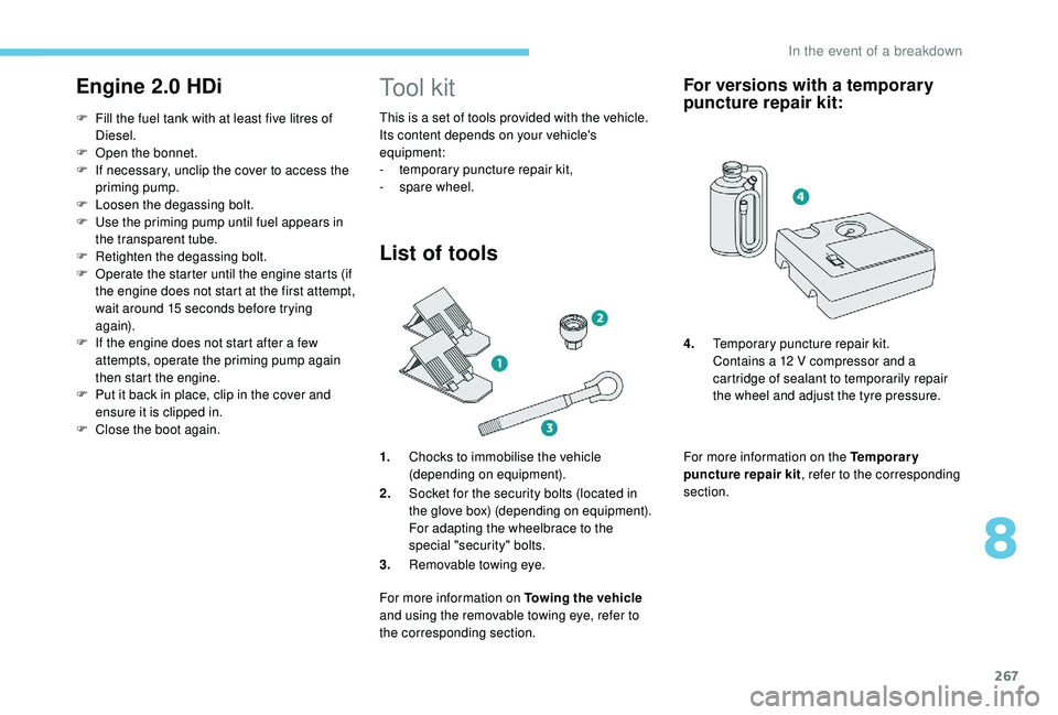
List of tools
1.Chocks to immobilise the vehicle
(depending on equipment).
2. Socket for the security bolts (located in
the glove box) (depending on equipment).
For adapting the wheelbrace to the
special "security" bolts.
3. Removable towing eye.
For more information on Towing the vehicle
and using the removable towing eye, refer to
the corresponding section.
For versions with a temporary
puncture repair kit:
For more information on the Temporary
puncture repair kit , refer to the corresponding
section. 4. Temporary puncture repair kit.
Contains a 12 V compressor and a
cartridge of sealant to temporarily repair
the wheel and adjust the tyre pressure.
8
In the event of a breakdown
Page 270 of 404
268
For more information on the Spare wheel, refer
to the corresponding section. All of these tools are specific to your
vehicle and may vary depending on
equipment.
Do not use them for any other purposes.
The jack must only be used to change
a wheel with a damaged or punctured tyre.
Do not use any jack other than the one
supplied with this vehicle.
If the vehicle does not have its original
jack, contact a PEUGEOT dealer or a
qualified workshop to obtain the correct
jack for it.
The jack meets European standards,
as defined in the Machinery Directive
2006/42/CE.
The jack does not require any
maintenance.
Access to the tools
Some of the tools are stored beneath the floor
against the boot sill.
The left box contains the wheelbrace and its
extension piece.
The right box contains the wheel chocks and
the towing eye.
To gain access to them:
F
o
pen the boot,
F
f
old the concertina floors back,
F
i
nstall the third row seats,
F
u
nclip the required tools from the boot sill
trim.
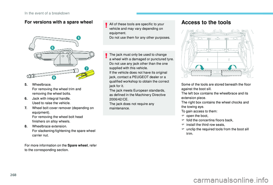
For versions with a spare wheel
5. Wheelbrace.
For removing the wheel trim and
removing the wheel bolts.
6. Jack with integral handle.
Used to raise the vehicle.
7. Wheel bolt cover remover (depending on
equipment).
For removing the wheel bolt head
finishers on alloy wheels.
8. Wheelbrace extension.
For slackening/tightening the spare wheel
carrier nut.
In the event of a breakdown
Page 271 of 404
269
For versions with a temporary
puncture repair kit
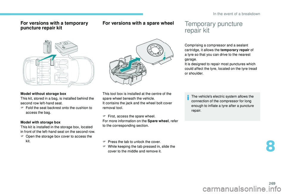
Model without storage box
This kit, stored in a bag, is installed behind the
second row left-hand seat.
F
F
old the seat backrest onto the cushion to
access the bag.
Model with storage box
This kit is installed in the storage box, located
in front of the left-hand seat on the second row.
F
O
pen the storage box cover to access the
kit.
For versions with a spare wheel
F First, access the spare wheel.
For more information on the Spare wheel , refer
to the corresponding section.
F
P
ress the tab to unlock the cover.
F
W
hile keeping the tab pressed in, slide the
cover to the middle and remove it.
This tool box is installed at the centre of the
spare wheel beneath the vehicle.
It contains the jack and the wheel bolt cover
removal tool.
Temporary puncture
repair kit
Comprising a compressor and a sealant
cartridge, it allows the temporary repair
of
a tyre so that you can drive to the nearest
garage.
It is designed to repair most punctures which
could affect the tyre, located on the tyre tread
or shoulder.
The vehicle's electric system allows the
connection of the compressor for long
enough to inflate a tyre after a puncture
repair.
8
In the event of a breakdown
Page 272 of 404
270
Composition of the kit
1.12 V compressor, with integral pressure
gauge.
2. Sealant cartridge, with integral hose.
3. Speed limit sticker.
The speed limit sticker must be secured
to the interior of the vehicle in the driver's
field of vision, to remind you that a wheel
is in temporary use.
Do not exceed a speed of 50
mph
(80
km/h) when driving with a tyre repaired
using this type of kit.
Repair procedure
F Switch off the ignition.
F S ecure the speed limit sticker inside the
vehicle.
F
U
ncoil the pipe stowed under the
compressor.
F
R
emove the valve cap from the tyre to be
repaired, and place it in a clean area.
F
C
onnect the pipe from the compressor to
the bottle of sealant.
Avoid removing any foreign bodies which
have penetrated into the tyre. F
T
urn the sealant bottle and secure it in the
cut-out provided on the compressor.
F
C
onnect the hose from the bottle of sealant
to the valve of the tyre to be repaired and
tighten firmly.
In the event of a breakdown
Page 275 of 404
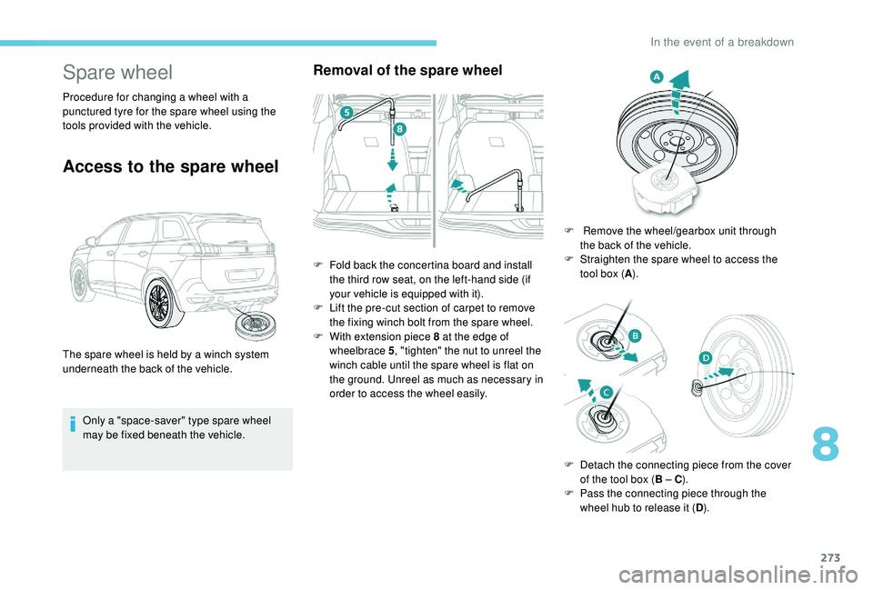
273
Spare wheel
Procedure for changing a wheel with a
punctured tyre for the spare wheel using the
tools provided with the vehicle.
Access to the spare wheel
Only a "space-saver" type spare wheel
may be fixed beneath the vehicle.
Removal of the spare wheel
The spare wheel is held by a winch system
underneath the back of the vehicle.F
F
old back the concertina board and install
the third row seat, on the left-hand side (if
your vehicle is equipped with it).
F
L
ift the pre-cut section of carpet to remove
the fixing winch bolt from the spare wheel.
F
W
ith extension piece 8 at the edge of
wheelbrace 5 , "tighten" the nut to unreel the
winch cable until the spare wheel is flat on
the ground. Unreel as much as necessary in
order to access the wheel easily. F
R
emove the wheel/gearbox unit through
the back of the vehicle.
F
S
traighten the spare wheel to access the
tool box ( A).
F
D
etach the connecting piece from the cover
of the tool box ( B – C).
F
P
ass the connecting piece through the
wheel hub to release it ( D).
8
In the event of a breakdown