Page 293 of 566
291
3008-2_en_Chap07_infos-pratiques_ed01-2016
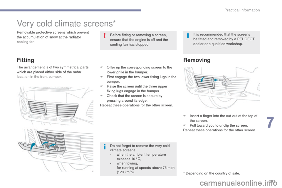
Very cold climate screens*
Removable protective screens which prevent
the accumulation of snow at the radiator
cooling fan.Before fitting or removing a screen,
ensure that the engine is off and the
cooling fan has stopped.
* Depending on the country of sale.It is recommended that the screens
be fitted and removed by a PEUGEOT
dealer or a qualified workshop.
Fitting
The arrangement is of two symmetrical parts
which are placed either side of the radar
location in the front bumper.
Removing
F Insert a finger into the cut-out at the top of
the screen.
F
P
ull toward you to unclip the screen.
Repeat these operations for the other screen.
Do not forget to remove the very cold
climate screens:
-
w
hen the ambient temperature
exceeds 10° C,
-
w
hen towing,
-
f
or running at speeds above 75 mph
(120 km/h).
F
O
ffer up the corresponding screen to the
lower grille in the bumper.
F
F
irst engage the two lower fixing lugs in the
b u m p e r.
F
R
aise the screen until the three upper
fixing lugs engage in the bumper.
F
C
heck that the screen is secure by
pressing around its edge.
Repeat these operations for the other screen.
7
Practical information
Page 296 of 566
294
3008-2_en_Chap07_infos-pratiques_ed01-2016
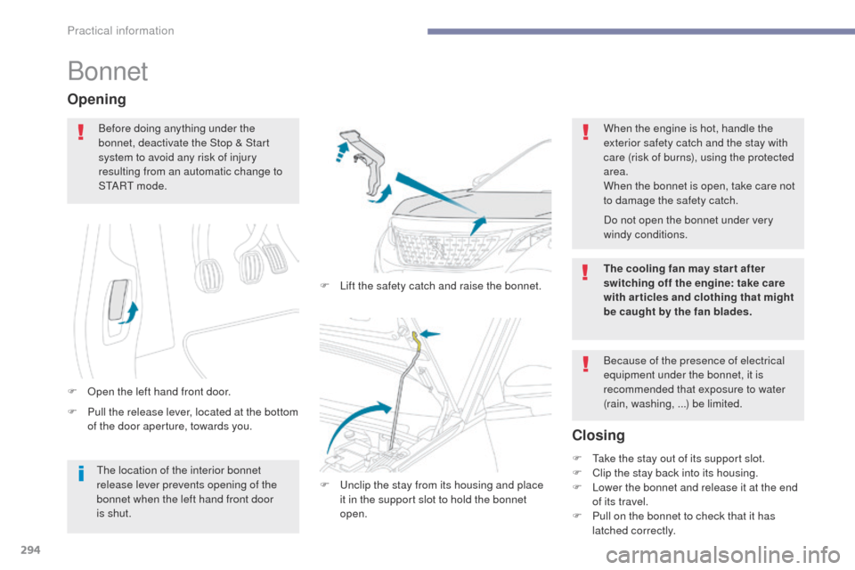
Bonnet
F Pull the release lever, located at the bottom of the door aperture, towards you.
Opening
F Open the left hand front door. F
L
ift the safety catch and raise the bonnet.
Closing
Before doing anything under the
bonnet, deactivate the Stop & Start
system to avoid any risk of injury
resulting from an automatic change to
S TA R T m o d e .
When the engine is hot, handle the
exterior safety catch and the stay with
care (risk of burns), using the protected
area.
When the bonnet is open, take care not
to damage the safety catch.
Because of the presence of electrical
equipment under the bonnet, it is
recommended that exposure to water
(rain, washing, ...) be limited.
F
U
nclip the stay from its housing and place
it in the support slot to hold the bonnet
open. F
T
ake the stay out of its support slot.
F
C
lip the stay back into its housing.
F
L
ower the bonnet and release it at the end
of its travel.
F
P
ull on the bonnet to check that it has
latched correctly.
The location of the interior bonnet
release lever prevents opening of the
bonnet when the left hand front door
is shut. Do not open the bonnet under very
windy conditions.
The cooling fan may star t after
switching off the engine: take care
with articles and clothing that might
be caught by the fan blades.
Practical information
Page 304 of 566
302
3008-2_en_Chap07_infos-pratiques_ed01-2016
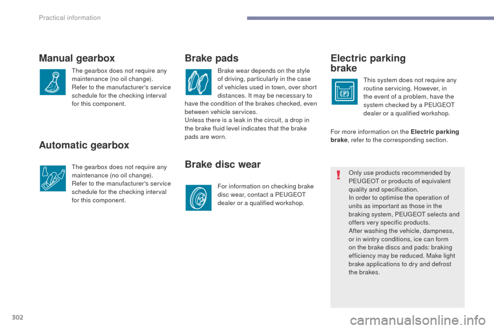
Automatic gearbox
The gearbox does not require any
maintenance (no oil change).
Refer to the manufacturer's service
schedule for the checking interval
for this component.
Electric parking
brake
This system does not require any
routine servicing. However, in
the event of a problem, have the
system checked by a PEUGEOT
dealer or a qualified workshop.
Brake pads
Brake wear depends on the style
of driving, particularly in the case
of vehicles used in town, over short
distances. It may be necessary to
Brake disc wear
For information on checking brake
disc wear, contact a PEUGEOT
dealer or a qualified workshop.For more information on the Electric parking
brake
, refer to the corresponding section.
Manual gearbox
The gearbox does not require any
maintenance (no oil change).
Refer to the manufacturer's service
schedule for the checking interval
for this component.
Only use products recommended by
PEUGEOT or products of equivalent
quality and specification.
In order to optimise the operation of
units as important as those in the
braking system, PEUGEOT selects and
offers very specific products.
After washing the vehicle, dampness,
or in wintry conditions, ice can form
on the brake discs and pads: braking
efficiency may be reduced. Make light
brake applications to dry and defrost
the brakes.
have the condition of the brakes checked, even
between vehicle services.
Unless there is a leak in the circuit, a drop in
the brake fluid level indicates that the brake
pads are worn.
Practical information
Page 309 of 566
307
3008-2_en_Chap08_en cas-de-panne_ed01-2016
Warning triangle
As a safety precaution, before leaving your vehicle to set up and install the triangle, switch on the hazard warning lamps and put on your high visibility
vest.
Storage compartment
A compartment for stowing a warning triangle is
provided in the tailgate interior trim.
F
O
pen the tailgate.
F
R
elease the cover by turning the fixing a
quarter turn anti-clockwise.
For other versions, refer to the
instructions provided with the triangle.
Assembling the triangle
For versions supplied with a triangle as original
equipment:
F
r
emove the triangle from its case,
F
u
nfold the legs,
F
o
pen out the two sides of the triangle,
F
c
lip together to complete the assembly.
Positioning the triangle
F Place the triangle behind the vehicle, as required by local legislation.
8
In the event of a breakdown
Page 311 of 566
309
3008-2_en_Chap08_en cas-de-panne_ed01-2016
Tool kit
This is a set of tools provided with the vehicle.
Its content depends on your vehicle's
equipment:
-
t
emporary puncture repair kit,
-
spar
e wheel.Access to the tools
The main tools are stowed in the boot under
t h e f l o o r.
For access to them:
F
o
pen the boot,
F
p
lace the adjustable boot floor in the high
position,
F
r
aise the floor past the two retractable
stops,
F
l
ay the floor on these two stops to hold it
up.For versions with a temporary
puncture repair kit:
F unclip the two fixings to open its cover.
8
In the event of a breakdown
Page 313 of 566
311
3008-2_en_Chap08_en cas-de-panne_ed01-2016
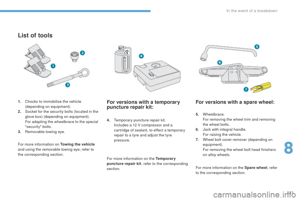
List of tools
4. Temporary puncture repair kit. Includes a 12 V compressor and a
cartridge of sealant, to effect a temporary
repair to a tyre and adjust the tyre
pressure.
For more information on Towing the vehicle
and using the removable towing eye, refer to
the corresponding section. 1.
C
hocks to immobilise the vehicle
(depending on equipment).
2.
S
ocket for the security bolts (located in the
glove box) (depending on equipment). F
or adapting the wheelbrace to the special
"security" bolts.
3.
R
emovable towing eye.
For versions with a temporary
puncture repair kit:
For more information on the Temporary
puncture repair kit , refer to the corresponding
section.
For versions with a spare wheel:
5. Wheelbrace. F
or removing the wheel trim and removing
the wheel bolts.
6.
J
ack with integral handle.
F
or raising the vehicle.
7.
W
heel bolt cover remover (depending on
equipment).
F
or removing the wheel bolt head finishers
on alloy wheels.
For more information on the Spare wheel , refer
to the corresponding section.
8
In the event of a breakdown
Page 315 of 566
313
3008-2_en_Chap08_en cas-de-panne_ed01-2016
Repair procedure
F Switch off the ignition.
F S ecure the speed limit sticker inside the
vehicle.
Avoid removing any foreign bodies
which have penetrated into the tyre.
F
U
ncoil the pipe stowed under the
compressor.
F
C
onnect the pipe from the compressor to
the sealant cartridge. F
R emove the valve cap from the tyre to be
repaired, and place it in a clean area.
F
C
onnect the hose from the sealant
cartridge to the valve of the tyre to be
repaired and tighten firmly.
F
T urn the sealant cartridge and secure it in
the cut-out provided on the compressor.
8
In the event of a breakdown
Page 316 of 566
314
3008-2_en_Chap08_en cas-de-panne_ed01-2016
If after around 5 to 7 minutes the
pressure is not attained, this indicates
that the tyre is not repairable; contact
a PEUGEOT dealer or a qualified
workshop for assistance.
Take care, the sealant product is
harmful if swallowed and causes
irritation to the eyes.
Keep this product out of the reach of
children.
The use-by date is marked on the
cartridge.
After use, do not discard the
cartridge by the roadside, take it to a
PEUGEOT dealer or an authorised
waste disposal site.
Don't forget to obtain a new sealant
cartridge, available from a PEUGEOT
dealer or a qualified workshop.
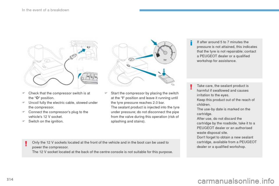
F
C
heck that the compressor switch is at
the
" O " position.
F
U
ncoil fully the electric cable, stowed under
the compressor.
F
C
onnect the compressor's plug to the
vehicle's 12 V socket.
F
S
witch on the ignition. F
S
tart the compressor by placing the switch
at the " I" position and leave it running until
the tyre pressure reaches 2.0 bar.
T
he sealant product is injected into the tyre
under pressure; do not disconnect the pipe
from the valve during this operation (risk of
splashing and stains).
Only the 12 V sockets located at the front of the vehicle and in the boot can be used to
power the compressor.
The 12 V socket located at the back of the centre console is not suitable for this purpose.
In the event of a breakdown