2017 MITSUBISHI L200 change time
[x] Cancel search: change timePage 293 of 426

NOTElIf the Bluetooth ®
2.0 interface cannot recog-
nise the Bluetooth ®
compatible cellular
phone or the connection takes too much time, the voice guide will say “Import con- tact has timed out” and then the system will
cancel the registration. In such case, start
over again from Step 1.
l Pressing the HANG-UP button or pressing
and holding the SPEECH button will cancelthe registration.
7. When the reception is complete, the
voice guide will say “
like to use for these numbers?”
Say the name you want to register for
this phone book entry.
NOTEl If the entered name is already used for other
phone book entry or similar to a name used
for other phone book entry, that name cannot
be registered.8. The voice guide will say “Adding
When the confirmation function is on, the system will ask if the name is cor-
rect. Answer “Yes”.
Answer “No”, and the voice guide will say “Name please”. Register a differentname.
9. The voice guide will say “Numbers
saved”.
10. The voice guide will say “Would you
like to import another contact?”
Answer “Yes” if you want to continue
with the registration. You can continueto register a new phone book entry from
Step 5.
Answer “No” to return to the main menu.To change the content registered in the ve-
hicle phone book
E00739800024
You can change or delete a name or tele- phone number registered in the vehicle phonebook.
You can also listen to the list of names regis-
tered in the vehicle phone book.
NOTEl The system must have at least one entry.Editing a telephone number
1. Press the SPEECH button.
2. Say “Phone book”.
3. The voice guide will say “Select one of
the following: new entry, edit number, edit name, list names, delete, erase all, or
import contact.” Say “Edit number”.
4. The voice guide will say “Please say the
name of the entry you would like to edit, or say list names.” Say the name of the
phone book entry you want to edit.NOTEl Say “List names,” and the names registered
in the phone book will be read out in order.
Refer to “Listening to the list of registered names” on page 7-92.
5. The voice guide will say “Home, work,
mobile or other?” Select and say the lo- cation where the telephone number youwant to change or add is registered.
When the confirmation function is on,
the system will check the target name
and location again. Answer “Yes” if you want to continue with the editing.
Answer “No” to return to Step 3.
6. The voice guide will say “Number
please”. Say the telephone number you
want to register.
Bluetooth ®
2.0 interface*
7-91OKTE17E1For pleasant driving7
Page 296 of 426

Up to 7 mobile phone books, each containing
up to 1,000 names, can be registered.
The Bluetooth ®
2.0 interface automatically
converts from text to voice the names regis- tered in the transferred phone book entries,
and creates names.NOTEl Only the mobile phone book transferred
from the connected cellular phone can be
used with that cellular phone.
l You cannot change the names and telephone
numbers in the phone book entries registered
in the mobile phone book. You cannot select and delete specific phone book entries, ei- ther.
To change or delete any of the above, change the applicable information in the
source phone book of the cellular phone and then transfer the phone book again.
To import a devices phone book
Follow the steps below to transfer to the mo- bile phone book the phone book stored in the
cellular phone.
NOTEl Transfer should be completed while the ve-
hicle is parked. Before transferring, makesure that the vehicle is parked in a safe loca-
tion.
l The already stored phone book in the mobile
phone book is overwritten by the storedphone book in the cellular phone.
l All or part of data may not be transferred,
even when the cellular phone supports Blue-
tooth ®
, depending on the compatibility of
the device.
l Only a home, a work, and a mobile number
can be imported.
l The maximum supported telephone number
length is 19 digits. Any telephone number of
20 digits or more will be truncated to the first 19 digits.
l If telephone numbers contain characters oth-
er than 0 to 9, *, # or +, these characters aredeleted before the transfer.
l For the connection settings on the cellular
phone side, refer to the instructions for the
cellular phone.
1. Press the SPEECH button.
2. Say “Phone book.”
3. The voice guide will say “Select one of
the following: new entry, edit number, edit name, list names, delete, erase all, or
import contact.” Say “Import contact.”
4. The voice guide will say “Would you
like to import a single entry or all con-
tacts?” Say “All contacts.”
5. The voice guide will say “Importing the
contact list from the mobile phone book. This may take several minutes to com-
plete. Would you like to continue?” An- swer “Yes,” transferring to the mobile
phone book the phone book stored in the cellular phone will start.
Answer “No,” to return to the main menu.NOTEl The transfer may take some time to com-
plete depending on the number of contacts.
l If the Bluetooth ®
2.0 interface could not be
connected to the Bluetooth ®
compatible cel-
lular phone, the voice guide will say “Un- able to transfer contact list from phone” and
then the system will return to the main menu.
l If you press the
HANG-UP button or press
and hold the SPEECH button during the data
transfer, the transfer will be cancelled and
the system will return to the main menu.
l If an error occurs during the data transfer, all
transfer will be cancelled and the voice
guide will say “Unable to complete the phone book import” and then the system willreturn to the main menu.
l If there are no contacts in the phone book,
the voice guide will say “There are no con- tacts on the connected phone.”
Bluetooth ®
2.0 interface*
7-94OKTE17E1For pleasant driving7
Page 304 of 426

CAUTIONlDo not touch the heating element or the cig-
arette lighter housing, hold the knob only to prevent burns.
l Do not allow children to operate or play with
the cigarette lighter as burns may occur.
l Something is wrong with the cigarette light-
er if it does not pop back out within approxi-
mately 30 seconds of being pushed in.
Pull it out and have the problem corrected at MITSUBISHI MOTORS Authorized Serv-
ice Point.
l Do not use any electric appliance that is not
approved by MITSUBISHI MOTORS . Do-
ing so could damage the socket. If you used
the cigarette lighter after damaging the sock- et, the cigarette lighter might pop out or fail
to come out after being pushed in.
l When the cigarette lighter socket is used as a
power source for an electric appliance, be sure that the electric appliance operates at
12 V and has an electric capacity of 120 W or less. In addition, long use of the electricappliance without running the engine may
run down the battery.Accessory socket
E00711602620
The accessory socket can be used while theignition switch or the operation mode is in
ON or ACC.
To use a plug-in type accessory, open the lid,
and insert the plug in the accessory socket.CAUTIONl Be sure to use a “plug-in” type accessory op-
erating at 12 V and at 120 W or less.
When using more than one socket at the same time, make sure that the electrical ac-
cessories are 12 V accessories and that the total power consumption does not exceed
120 W.
l Long use of the electric appliance without
running the engine may run down the bat- tery.
l When the accessory socket is not in use, be
sure to close the lid, because the socketmight become clogged by foreign materialand be short-circuited.Digital clock*
E00711801540
The digital clock indicates the time with the
ignition switch or the operation mode is in
ON or ACC.
To set the time
Set the time by pressing the various buttons
as described below.
1- To adjust the hour
2- To adjust the minutes
3- To reset the minutes to zero
10:30 - 11:29...... Changes to 11:00
11:30 - 12:29...... Changes to 12:00
Accessory socket
7-102OKTE17E1For pleasant driving7
Page 318 of 426

SituationIndication lampCauseSolutionRed lampGreen lampExtinguishesIlluminatesA conversation with an operator
of the emergency call centre is
available.Mutually confirm the details of
the emergency call with the oper-
ator of the emergency call centre.
If the green lamp does not extin-
guish even after the emergency
call ends, have the system inspec-
ted at a MITSUBISHI MOTORS
Authorized Service Point.When the emergency call
failedIlluminates (for ap-
proximately 60 sec-
onds)ExtinguishesThe emergency call failed.Make an emergency call again, or
directly arrange an emergency ve-
hicle or road service with the
nearest public telephone, etc.Test Mode
You can check if the system is in the normal
standby state by the following process.
Before operation, stop the vehicle in a safe place, with good visibility, where radio
waves can be transmitted and received.
Change to Test Mode
1. When the ignition switch or the opera-
tion mode is set to “OFF”, set the igni- tion switch or the operation mode to
“ON” while pressing the SOS switch.
2. After setting the ignition switch or the
operation mode to “ON”, perform Steps
3 and 4 within 10 seconds.
3. Release your finger from the SOS
switch.
4. Press the SOS switch 3 or more times.
5. After approximately 10 seconds from
Step 2, the red lamp and the green lampextinguish. After that, the buzzer sounds
3 times.NOTEl If the buzzer does not sound, repeat the
process from Step 1.
6. Approximately 60 seconds later, the
green lamp blinks. If you press the SOS switch within 20 seconds, the mode
changes to the test mode.
NOTEl When the red lamp blinks instead of the
green lamp, move the vehicle in a safe place, with good visibility, where radio waves can
be transmitted and received, then repeat the process from Step 1.
7. Within approximately 20 seconds after
the mode has changed to the test mode,
press the SOS switch for one of the fol- lowing periods to select the desired test
type.
l 10 seconds or more: Report test to the
emergency call centre
ERA-GLONASS*
8-06OKTE17E1For emergencies8
Page 330 of 426
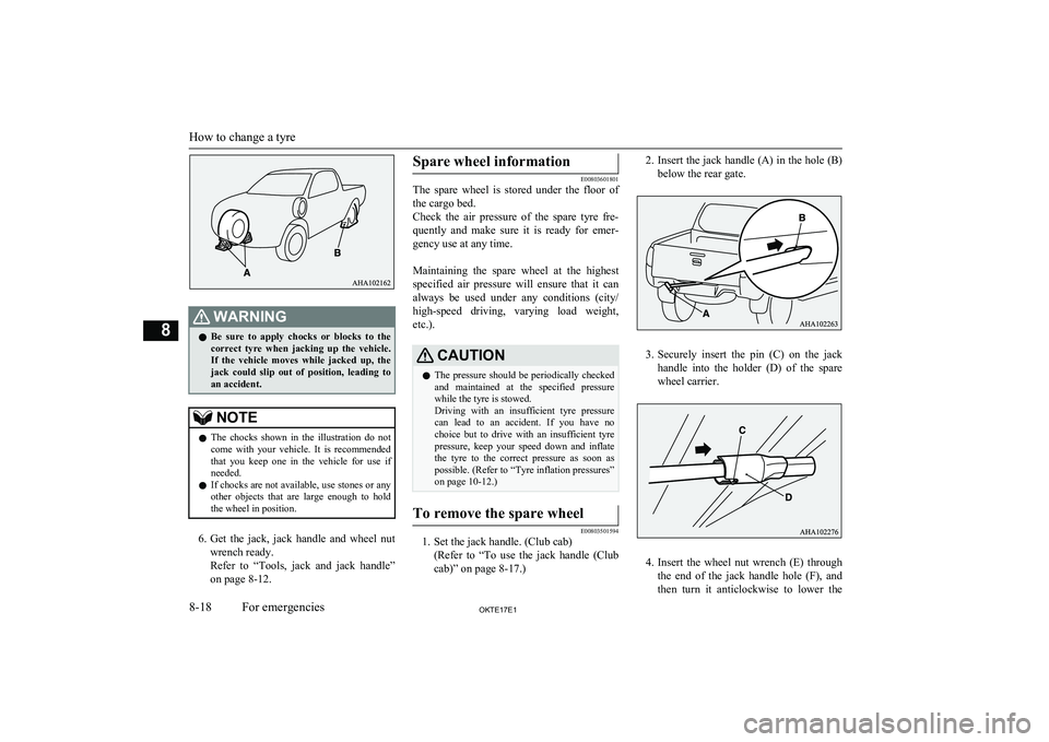
WARNINGlBe sure to apply chocks or blocks to the
correct tyre when jacking up the vehicle.If the vehicle moves while jacked up, the
jack could slip out of position, leading to
an accident.NOTEl The chocks shown in the illustration do not
come with your vehicle. It is recommended
that you keep one in the vehicle for use if needed.
l If chocks are not available, use stones or any
other objects that are large enough to hold the wheel in position.
6. Get the jack, jack handle and wheel nut
wrench ready.
Refer to “Tools, jack and jack handle” on page 8-12.
Spare wheel information
E00803601801
The spare wheel is stored under the floor of
the cargo bed.
Check the air pressure of the spare tyre fre-
quently and make sure it is ready for emer- gency use at any time.
Maintaining the spare wheel at the highest
specified air pressure will ensure that it can always be used under any conditions (city/ high-speed driving, varying load weight,
etc.).
CAUTIONl The pressure should be periodically checked
and maintained at the specified pressure while the tyre is stowed.
Driving with an insufficient tyre pressure
can lead to an accident. If you have no choice but to drive with an insufficient tyre
pressure, keep your speed down and inflate the tyre to the correct pressure as soon as
possible. (Refer to “Tyre inflation pressures”
on page 10-12.)To remove the spare wheel
E00803501594
1. Set the jack handle. (Club cab)
(Refer to “To use the jack handle (Clubcab)” on page 8-17.)
2. Insert the jack handle (A) in the hole (B)
below the rear gate.
3. Securely insert the pin (C) on the jack
handle into the holder (D) of the spare
wheel carrier.
4. Insert the wheel nut wrench (E) through
the end of the jack handle hole (F), and
then turn it anticlockwise to lower the
How to change a tyre
8-18OKTE17E1For emergencies8
Page 333 of 426

WARNINGlStop jacking up the vehicle as soon as the
tyre is raised off the ground. It is danger-
ous to raise the vehicle any higher.
l Do not get under your vehicle while using
the jack.
l Do not bump the raised vehicle or leave it
sitting on the jack for a long time. Both are very dangerous.
l Do not use a jack except the one that
came with your vehicle.
l The jack should not be used for any pur-
pose other than to change a tyre.
l No one should be in your vehicle when us-
ing the jack.
l Do not start or run the engine while your
vehicle is on the jack.
l Do not turn the raised wheel. The tyres
still on the ground could turn and make your vehicle fall off the jack.
6. Remove the wheel nuts with the wheel
nut wrench, then take the wheel off.
CAUTIONl Handle the wheel carefully when changing
the tyre, to avoid scratching the wheel sur- face.
7. Clean out any mud, etc. on the hub sur-
face (G), hub bolts (H) or in the installa- tion holes (I) in the wheel, and then
mount the spare wheel.
WARNINGl Mount the spare wheel with the valve
stem (J) facing outboard. If you cannot see the valve stem (J), you have installed the wheel backwards.
Operating the vehicle with the spare
wheel installed backwards can cause vehi-
cle damage and result in an accident.8. Turn the wheel nuts clockwise by hand
to initially tighten them.
[Type 1: On vehicles with steel wheels]
Temporarily tighten the wheel nuts by hand until the tapered parts of the wheel nuts make light contact with the seats of the wheel holes and the wheel is not
loose.
[Type 2: On vehicles with aluminium wheels]
Temporarily tighten the wheel nuts by
hand until the flange parts of the wheel nuts make light contact with the wheel
and the wheel is not loose.
How to change a tyre
8-21OKTE17E1For emergencies8 Type 1
Page 402 of 426

Bulb location and capacity.............................. 10-22C
Capacities........................................................ 11-18
Card holder...................................................... 7-100
Cargo loads........................................................6-83
Catalytic converter.......................................... 10-03
Cautions on handling of 4-wheel drive vehicles................................................... 6-52
CD player.................................................. 7-18,7-39
Central door locks............................................. 3-17
Centre console under tray................................7-106
Charge warning lamp........................................ 5-16 Check engine warning lamp.............................. 5-15
Child restraint.................................................... 4-11 Caution for installing the child re-straint on vehicles with a front
passenger airbag.................................. 4-11,4-26
Child restraint system with ISOFIX mountings.................................................... 4-21
i-Size child restraint system.......................... 4-15
Installing a child restraint system to the lower anchorage (ISOFIX
child restraint mountings) and
tether anchorage...........................................4-21
Suitability for various ISOFIX positions...... 4-14
Suitability for various seating positions........ 4-16
Child-protection rear doors............................... 3-20
Cigarette lighter............................................... 7-101
Cleaning Chrome parts................................................. 9-05
Exterior of your vehicle................................ 9-03
Genuine leather............................................. 9-03
Interior of your vehicle................................. 9-02
Plastic parts................................................... 9-04
Plastic, fabric and flocked parts.................... 9-02
Polishing....................................................... 9-04 Washing........................................................ 9-03
Waxing.......................................................... 9-04
Clock............................................................... 7-102
Clutch Fluid.................................................. 10-09,11-18
Coat hook........................................................ 7-109
Combination headlamps and dipper switch...... 5-17
Convenient hook............................................. 7-108
Coolant (engine)....................................10-06,11-18
Cruise control.................................................... 6-63 Indication lamp............................................. 6-64
Switch........................................................... 6-64
Cup holder....................................................... 7-107
D
Daytime running lamps..................................... 5-19Bulb capacity.............................................. 10-22
Replacement................................................ 10-27
Demister (rear window).................................... 5-27
Diesel particulate filter (DPF)........................... 6-21 Warning lamp................................................6-21
Diesel preheat indication lamp.......................... 5-14
Differential oil................................................. 11-18
Digital clock.................................................... 7-102 Time Setting......................................... 7-37,7-70
Dimensions...................................................... 11-04
Dipper (High/Low beam change)......................5-19
Display Indicator............................................... 7-35
Disposal information for used batteries............ 2-06
Doors Central door locks......................................... 3-17
Child-protection rear doors........................... 3-20
Dead Lock System........................................ 3-18
Door ajar warning lamp................................ 5-16
Locking and unlocking................................. 3-15
To open or close the rear door (Club cab).... 3-16
Driving, alcohol and drugs................................ 6-02
E
Easy select 4WD............................................... 6-352WD/4WD operation indication lamp.. 6-36,6-38
Low-range indication lamp........................... 6-38
Economical driving........................................... 6-02
Electric window control.................................... 3-21 Safety mechanism......................................... 3-23
Switch........................................................... 3-21
Timer function.............................................. 3-23
Electrical system............................................. 11-16
Electronic immobilizer (Anti-theft starting system)................................................ 3-03
Emergency key.................................................. 3-11
Emergency starting............................................8-08
Emergency stop signal system.......................... 6-56
Engine specifications.......................................11-15
Engine switch.................................................... 6-14
Engine Check engine warning lamp..........................5-15
Coolant..............................................10-06,11-18 Diesel preheat indication lamp......................5-14Engine coolant temperature display.............. 5-06
Model.......................................................... 11-03
Number....................................................... 11-03
Oil..................................................... 10-05,11-18
Alphabetical index
12- 2 OKTE17E1Alphabetical index
Page 403 of 426

Oil pressure warning lamp............................ 5-16
Overheating................................................... 8-09
Safety and disposal information for used engine oil............................................. 2-06
Specifications.............................................. 11-15
Entering or leaving the vehicle..........................2-04
ERA-GLONASS............................................... 8-02
Exterior and interior lamp operation............... 10-16
F
First-aid kit and warning triangleband for securing........................................... 7-109
Floor console box............................................ 7-106
Fluid Automatic transmission fluid...................... 11-18
Brake fluid........................................ 10-08,11-18
Clutch fluid....................................... 10-09,11-18
Engine coolant.................................. 10-06,11-18
Power steering fluid.......................... 10-09,11-18
Washer fluid..................................... 10-08,11-18
Front fog lamps
Bulb capacity.............................................. 10-22
Indication lamp............................................. 5-13
Replacement................................................ 10-27
Switch........................................................... 5-22
Front room lamp.............................................. 7-103
Bulb capacity.............................................. 10-23
Replacement................................................ 10-29
Front seats......................................................... 4-02
Front turn-signal lamps Bulb capacity.............................................. 10-22
Indication lamp............................................. 5-13
Replacement................................................ 10-25
Switch........................................................... 5-21
Frozen road warning..........................................5-06
Fuel consumption............................................ 11-17
Fuel remaining warning display........................ 5-07
Fuel Bleeding the fuel system............................... 8-11Filling the fuel tank....................................... 2-02Fuel filter indication lamp............................. 5-14
Fuel remaining display.................................. 5-07
Fuel remaining warning display....................5-07
Fuel selection................................................ 2-02
Modification/alterations to the electrical or fuel systems............................. 2-06
Removal of water from the fuel filter........... 8-11
Tank capacity................................................ 2-03
Fuses................................................................ 10-17
Fusible links.................................................... 10-17
G
General maintenance....................................... 10-16
General vehicle data........................................ 11-04
Genuine parts.....................................................2-06
Glove box........................................................ 7-105
Glove box lamp Bulb capacity.............................................. 10-23
Replacement................................................ 10-31
H
Hazard warning flasher switch.......................... 5-21
Hazard warning indication lamps......................5-13
HDMI terminal.................................................. 7-99
Head restraints................................................... 4-05
Headlamp levelling switch................................ 5-19
Headlamp washer switch...................................5-26
Headlamps Auto-cutout function..................................... 5-18Bulb capacity.............................................. 10-22
Daytime running lamps................................. 5-19 Dipper (High/Low beam change)................. 5-19
Headlamp flasher.......................................... 5-19
High-beam indication lamp...........................5-13
Lamp monitor buzzer.................................... 5-18
Replacement................................................ 10-24
Switch........................................................... 5-17
Heated mirror.................................................... 6-12
Switch........................................................... 5-27
Heated seats....................................................... 4-03
Heater........................................................ 7-04,7-09
High-mounted stop lamp Bulb capacity.............................................. 10-22
Hill start assist................................................... 6-55
Warning indicator......................................... 6-55
Hinges and latches lubrication........................ 10-16
Hooks Coat hook.................................................... 7-109Convenient hook......................................... 7-109
Horn switch....................................................... 5-28
I
If the vehicle breaks down................................ 8-07
Ignition switch................................................... 6-13
Indication and warning lamps........................... 5-12
Indication lamps........................................ 5-12,5-13
Inside rear-view mirror......................................6-08
Inspection and maintenance following rough road operation........................................ 6-52
Installation of accessories..................................2-04
Alphabetical index
12- 3
OKTE17E1Alphabetical index