2017 MERCEDES-BENZ GLE43AMG SUV ECU
[x] Cancel search: ECUPage 278 of 366
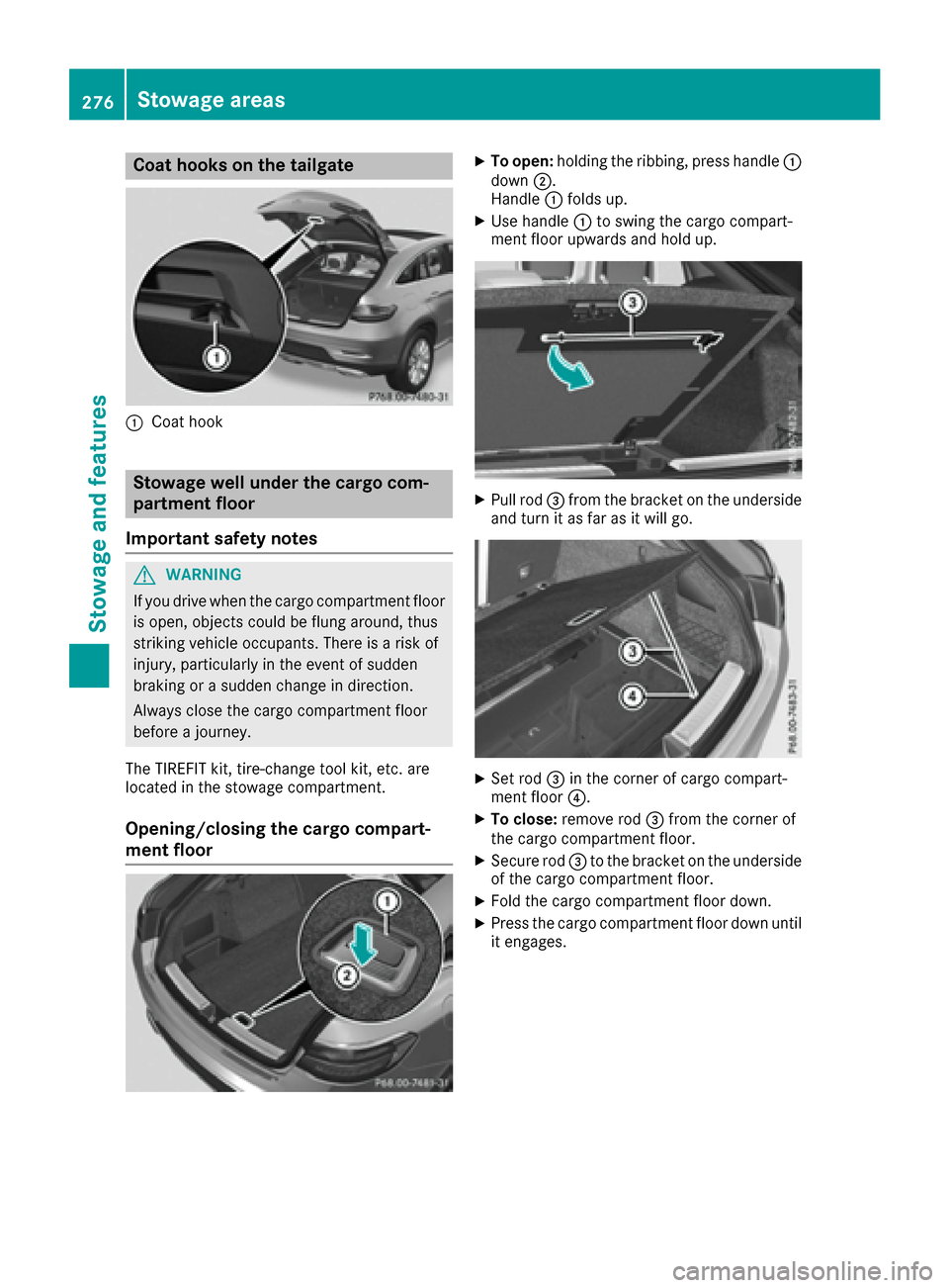
Coat hooks on the tailgate
:Coat hook
Stowage well under the cargo com-
partment floor
Important safety notes
GWARNING
If you drive when the cargo compartment floor is open, objects could be flung around, thus
striking vehicle occupants. There is a risk of
injury, particularly in the event of sudden
braking or a sudden change in direction.
Always close the cargo compartment floor
before a journey.
The TIREFIT kit, tire-change tool kit, etc. are
located in the stowage compartment.
Opening/closing the cargo compart-
ment floor
XTo open: holding the ribbing, press handle :
down ;.
Handle :folds up.
XUse handle :to swing the cargo compart-
ment floor upwards and hold up.
XPull rod =from the bracket on the underside
and turn it as far as it will go.
XSet rod =in the corner of cargo compart-
ment floor ?.
XTo close:remove rod =from the corner of
the cargo compartment floor.
XSecure rod =to the bracket on the underside
of the cargo compartment floor.
XFold the cargo compartment floor down.
XPress the cargo compartment floor down until
it engages.
276Stowage areas
Stowage and features
Page 279 of 366
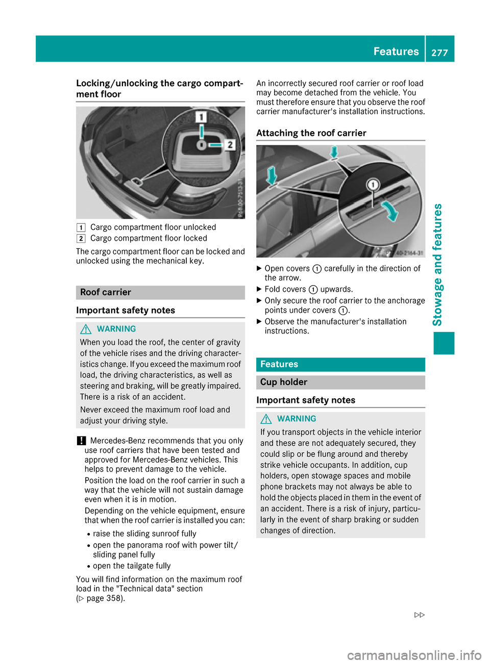
Locking/unlocking the cargo compart-
ment floor
1Cargo compartment floor unlocked
2Cargo compartment floor locked
The cargo compartment floor can be locked and
unlocked using the mechanical key.
Roof carrier
Important safety notes
GWARNING
When you load the roof, the center of gravity
of the vehicle rises and the driving character-
istics change. If you exceed the maximum roof
load, the driving characteristics, as well as
steering and braking, will be greatly impaired.
There is a risk of an accident.
Never exceed the maximum roof load and
adjust your driving style.
!Mercedes-Benz recommends that you only
use roof carriers that have been tested and
approved for Mercedes-Benz vehicles. This
helps to prevent damage to the vehicle.
Position the load on the roof carrier in such a
way that the vehicle will not sustain damage
even when it is in motion.
Depending on the vehicle equipment, ensure
that when the roof carrier is installed you can:
Rraise the sliding sunroof fully
Ropen the panorama roof with power tilt/
sliding panel fully
Ropen the tailgate fully
You will find information on the maximum roof
load in the "Technical data" section
(
Ypage 358). An incorrectly secured roof carrier or roof load
may become detached from the vehicle. You
must therefore ensure that you observe the roof
carrier manufacturer's installation instructions.
Attaching the roof carrier
XOpen covers
:carefully in the direction of
the arrow.
XFold covers :upwards.
XOnly secure the roof carrier to the anchorage
points under covers :.
XObserve the manufacturer's installation
instructions.
Features
Cup holder
Important safety notes
GWARNING
If you transport objects in the vehicle interior
and these are not adequately secured, they
could slip or be flung around and thereby
strike vehicle occupants. In addition, cup
holders, open stowage spaces and mobile
phone brackets may not always be able to
hold the objects placed in them in the event of
an accident. There is a risk of injury, particu-
larly in the event of sharp braking or sudden
changes of direction.
Features277
Stowage and features
Z
Page 280 of 366

RAlways stow objects in such a way that they
cannot be tossed about in these or similar
situations.
RAlways make sure that objects do not pro-
trude out of the stowage spaces, luggage
nets or stowage nets.
REnsure that closable stowage spaces are
shut before beginning your journey.
RAlways stow and secure heavy, hard, poin-
ted, sharp-edged, fragile or large objects in
the cargo compartment.
Observe the loading guidelines (
Ypage 270).
!Only use the cup holders for containers of
the right size and which have lids. The drinks
could otherwise spill.
!Do not expose drinks bottles in the cup
holder in the center console to continuous,
strong and direct sunlight. The passenger
compartment in the area of the center con-
sole can otherwise be damaged by the con-
centrated and reflected sunlight.
Do not keep the KEYLESS-GO key in the tem-
perature-controlled cup holder (
Ypage 278).
Otherwise, the KEYLESS-GO key will not be rec-
ognized.
The stowage compartments in the doors provide
space for bottles with a capacity of up to
34 fl. oz. (1.0 l).
The bottles are not secured or prevented from
tipping over. Therefore, do not place any open
drink containers in the stowage compartments.
Cup holder in the front-compartment
center console
:Cover
;Cup holder
XTo open: slide cover :to its foremost posi-
tion.
XTo close: pull cover :back as far as it will go.
You can remove the cup holder's rubber mat for
cleaning. Clean with clear, lukewarm water only.
Temperature-controlled cup holder in
the front-compartment center console
:Cup holder
;Residual heat indicator lamp
=Switch
The temperature-controlled cup holder can be
used to keep cold drinks cool and warm drinks
warm.
XTurn the SmartKey to position 2in the ignition
lock.
XTo switch on the cooling function: press
and hold button =until the blue indicator
lamp on the button lights up.
XTo switch on the heating function: press
and hold button =until the red indicator
lamp on the button lights up.
XTo switch off the function: press and hold
button =until the indicator lamp on the but-
ton goes out.
When the heating function is used, the metal
insert of the cup holder is heated. Once a certain
temperature is reached, residual heat indicator
lamp ;lights up. This means that the metal
insert of the cup holder is hot. For this reason,
you must not reach into the cup holder metal
insert.
Do not use hard or sharp objects to clean the
cup holder. Use only a soft cloth to clean it.
278Features
Stowage and features
Page 286 of 366
There is a risk of an accident and injury.
Leave the vehicle immediately in this or simi-lar situations as soon as it is safe to do so.
Move to a safe location along with other vehi-
cle occupants. In such situations, secure the
vehicle in accordance with national regula-
tions, e. g. with a warning triangle.
General notes
Observe the notes on system activation
(Ypage 283).
An emergency call is dialed automatically if an
air bag or Emergency Tensioning Device is trig-
gered. You cannot end an automatically trig-
gered emergency call yourself.
An emergency call can also be initiated man-
ually.
As soon as the emergency call has been initi-
ated, the indicator lamp in the SOS button
flashes. The Connecting Call
message
appears in the multifunction display.
The audio output is muted.
Once the connection has been made, the Call
Connectedmessage appears in the multifunc-
tion display.
All important information relating to the emer-
gency is transferred, for example:
Rcurrent location of the vehicle (as determined by the GPS system)
Rvehicle identification number
Rinformation on the severity of the accident
Shortly after the emergency call has been initi-
ated, a voice connection is automatically estab-
lished between the Customer Assistance Center
and the vehicle occupants.
RIf the vehicle occupants respond, the
Mercedes-Benz Customer Assistance Center
attempts to get more information on the
emergency.
RIf there is no response from the vehicle occu-
pants, an ambulance is immediately sent to
the vehicle.
If no voice connection can be established to the
Mercedes-Benz Customer Assistance Center,
the system has been unable to initiate an emer-
gency call.
This can occur, for example, if the relevant
mobile phone network is not available. The indi-
cator lamp in the SOS button flashes continu-
ously. The
Call Failed
message appears in the mul-
tifunction display and must be confirmed.
In this case, summon assistance by other
means.
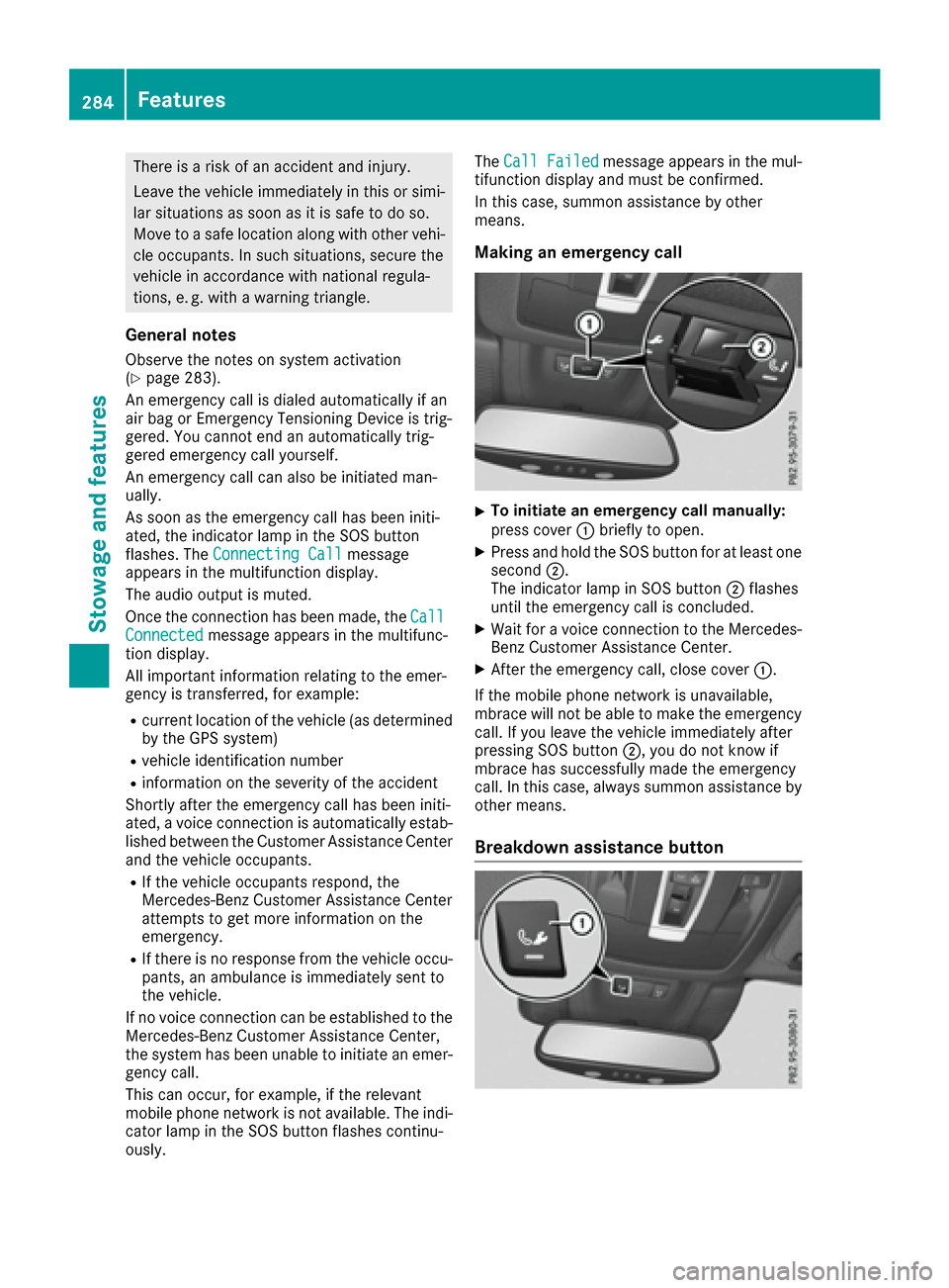
Making an emergency call
XTo initiate an emergency call manually:
press cover :briefly to open.
XPress and hold the SOS button for at least one
second ;.
The indicator lamp in SOS button ;flashes
until the emergency call is concluded.
XWait for a voice connection to the Mercedes-
Benz Customer Assistance Center.
XAfter the emergency call, close cover :.
If the mobile phone network is unavailable,
mbrace will not be able to make the emergency
call. If you leave the vehicle immediately after
pressing SOS button ;, you do not know if
mbrace has successfully made the emergency
call. In this case, always summon assistance by
other means.
Breakdown assistance button
284Features
Stowage and features
Page 294 of 366
operate in the frequency range of 280 to
433 MHz.
RReplace the batteries in garage door remote
controlA. This increases the likelihood that
garage door remote control Awill transmit a
strong and precise signal to the integrated
garage door opener.
RWhen programming, hold remote control A
at varying distances and angles and from but-
tons ;to? which you are programming. Try
various angles at a distance between 2and
8 inches (5to 20 cm) or at the same angle but
at varying distances.
RIf another remote control Ais available for
the same garage door drive, repeat the same
programming steps with this remote control
A. Before performing these steps, make sure
that new batteries have been installed in
garage door drive remote control A.
RNote that some remote controls only transmit
for a limited amount of time (the indicator
lamp on the remote control goes out). Press
buttonBon remote control Aagain before
transmission ends.
RAlign the antenna cable of the garage door
opener unit. This can improve signal recep-
tion/transmission.
Opening/closing the garage door
After it has been programmed, the integrated
garage door opener performs the function of the
garage door system remote control. Please also
read the operating instructions for the garage
door system.
XTurn the SmartKey to position 2in the ignition
lock (Ypage 125).
XPress buttons ;,=or? which you have
programmed to operate the garage door.
Garage door system with a fixed code: indi-
cator lamp :lights up green.
Garage door system with a rolling code: indi-
cator lamp :flashes green.
The transmitter will transmit a signal as long
as the button is pressed. The transmission is
halted after a maximum of ten seconds and
indicator lamp :lights up yellow.
XPress button ;,=or? again if necessary.
Clearing the memory
Make sure that you clear the memory of the
integrated garage door opener before selling the
vehicle.
XTurn the SmartKey to position 2in the ignition
lock (Ypage 125).
XPress and hold buttons ;and ?.
The indicator lamp initially lights up yellow
and then green.
XRelease buttons ;and ?.
The memory of the integrated garage door
opener in the rear-view mirror is cleared.
Floormats
GWARNING
Objects in the driver's footwell can restrict the pedal travel or obstruct a depressed pedal.
The operating and road safety of the vehicle is
jeopardized. There is a risk of an accident.
Make sure that all objects in the vehicle are
stowed correctly, and that they cannot enter
the driver's footwell. Install the floormats
securely and as specified in order to ensure
sufficient clearance for the pedals. Do not use
loose floormats and do not place floormats on
top of one another.
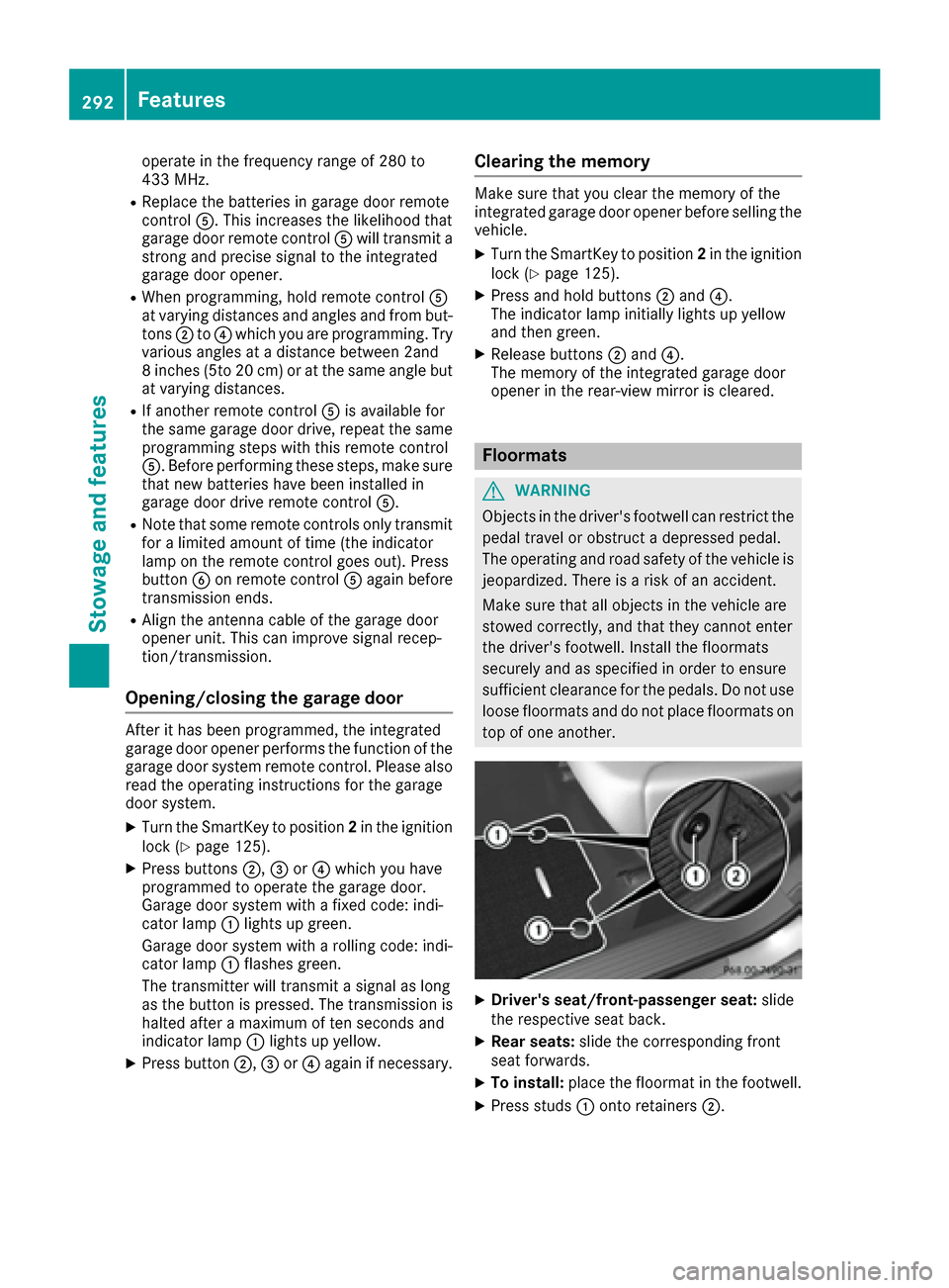
XDriver's seat/front-passenger seat: slide
the respective seat back.
XRear seats: slide the corresponding front
seat forwards.
XTo install: place the floormat in the footwell.
XPress studs :onto retainers ;.
292Features
Stowage and features
Page 298 of 366
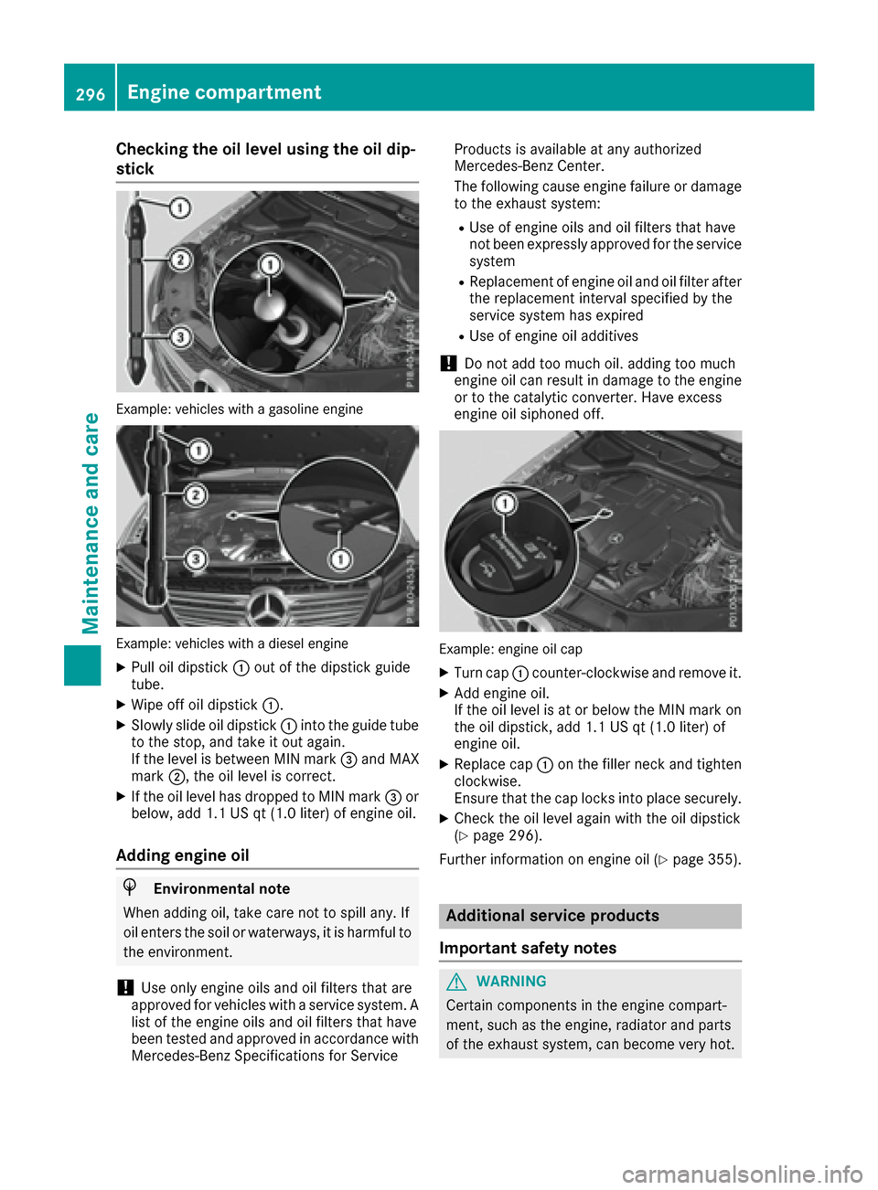
Checking the oil level using the oil dip-
stick
Example:vehicle swit h a gasolin eengin e
Example :vehicle swit h a diesel engin e
XPull oil dipstick :out of the dipstick guide
tube.
XWipe off oil dipstick :.
XSlowly slide oil dipstick :into the guide tube
to the stop, and take it out again.
If the level is between MIN mark =and MAX
mark ;, the oil level is correct.
XIf the oil level has dropped to MIN mark =or
below, add 1.1 US qt (1.0 liter) of engine oil.
Adding engine oil
HEnvironmental note
When adding oil, take care not to spill any. If
oil enters the soil or waterways, it is harmful to
the environment.
!Use only engine oils and oil filters that are
approved for vehicles with a service system. A list of the engine oils and oil filters that have
been tested and approved in accordance with
Mercedes-Benz Specifications for Service Products is available at any authorized
Mercedes-Benz Center.
The following cause engine failure or damage
to the exhaust system:
RUse of engine oils and oil filters that have
not been expressly approved for the service
system
RReplacement of engine oil and oil filter after
the replacement interval specified by the
service system has expired
RUse of engine oil additives
!Do not add too much oil. adding too much
engine oil can result in damage to the engine
or to the catalytic converter. Have excess
engine oil siphoned off.
Example :engine oil cap
XTurn cap :counter-clockwise and remove it.
XAdd engine oil.
If the oil level is at or below the MIN mark on
the oil dipstick, add 1.1 US qt (1.0 liter) of
engine oil.
XReplace cap :on the filler neck and tighten
clockwise.
Ensure that the cap locks into place securely.
XCheck the oil level again with the oil dipstick
(Ypage 296).
Further information on engine oil (
Ypage 355).
Additional service products
Important safety notes
GWARNING
Certain components in the engine compart-
ment, such as the engine, radiator and parts
of the exhaust system, can become very hot.
296Engine compartment
Maintenance and care
Page 304 of 366
!Do not park your vehicle for a long period of
time directly after cleaning, particularly after
cleaning the wheel rim with wheel cleaner.
Wheel cleaner can lead to the increased cor-
rosion of the brake discs and pads. Therefore,
drive for a few minutes after cleaning. By
heating up the brakes, the brake discs and
pads dry. The vehicle can then be parked for a
long period of time.
Cleaning the windows
GWARNING
You could become trapped by the windshield wipers if they start moving while cleaning the
windshield or wiper blades. There is a risk of
injury.
Always switch off the windshield wipers and
the ignition before cleaning the windshield or
wiper blades.
!Do not use dry cloths, abrasive products,
solvents or cleaning agents containing sol-
vents to clean the inside of the windows. Do
not touch the insides of the windows with
hard objects, e.g. an ice scraper or ring. There
is otherwise a risk of damaging the windows.
!Clean the water drainage channels of the
windshield and the rear window at regular
intervals. Deposits such as leaves, petals and pollen may under certain circumstances pre-
vent water from draining away. This can lead
to corrosion damage and damage to elec-
tronic components.
XClean the inside and outside of the windows
with a damp cloth and a cleaning product that
is recommended and approved by Mercedes-
Benz.
Cleaning wiper blades
GWARNING
You could become trapped by the windshield wipers if they start moving while cleaning the
windshield or wiper blades. There is a risk of
injury.
Always switch off the windshield wipers and
the ignition before cleaning the windshield or
wiper blades.
!Do not pull the wiper blade. Otherwise, the
wiper blade could be damaged.
!Do not clean wiper blades too often and do
not rub them too hard. Otherwise, the graph-
ite coating could be damaged. This could
cause wiper noise.
!Hold the wiper arm securely when folding
back. The windshield could be damaged if the
wiper arm smacks against it suddenly.
XFold the windshield wiper arms away from the
windshield (Ypage 110).
XCarefully clean the wiper blades with a damp
cloth.
XFold the windshield wiper arms back again
before switching on the ignition.
Cleaning the exterior lighting
!Only use cleaning agents or cleaning cloths
which are suitable for plastic light lenses.
Unsuitable cleaning agents or cleaning cloths
could scratch or damage the plastic light len- ses.
XClean the plastic lenses of the exterior light-
ing using a wet sponge and a mild cleaning
agent, e. g. Mercedes-Benz car shampoo or
cleaning cloths.
Cleaning the mirror turn signals
!Only use cleaning agents or cleaning cloths
that are suitable for plastic lenses. Unsuitable
cleaning agents or cleaning cloths could
scratch or damage the plastic lenses of the
mirror turn signals.
XClean the plastic lenses of the mirror turn sig-
nals in the exterior mirror housing using a wet
sponge and mild cleaning agent, e.g.
Mercedes-Benz car shampoo or cleaning
cloths.
Cleaning the side running board
!Do not clean the aluminum inserts of the
side running board with alkaline or acidic
cleaners, such as wheel cleaner. Do not use
acidic wheel cleaners to remove brake dust.
The aluminum inserts could otherwise be
damaged.
302Care
Maintenance and care
Page 308 of 366

Where will I find...?
Vehicle tool kit
General notes
The vehicle tool kit can be found in the stowage
well under the cargo compartment floor.
Apart from certain country-specific variations,
the vehicles are not equipped with a tire-change
tool kit. Some tools for changing a wheel are
specific to the vehicle. For more information on
which tools are required to perform a wheel
change on your vehicle, consult a qualified spe-
cialist workshop.
Necessary tire-changing tools can include, for
example:
RJack
RWheel chock
RLug wrench
RRatchet wrench
RAlignment bolt
Vehicles with a TIREFIT kit
:Jack
;Folding wheel chock
=Towing eye
?Alignment bolt
ATire inflation compressor
BLug wrench
CRatchet wrench
DTire sealant filler bottle
XOpen the tailgate.
XLift the cargo compartment floor upwards
(Ypage 276).
XUse the TIREFIT kit (Ypage 308).
Vehicles with a "Minispare" emergency
spare wheel
:Folding wheel chock
;Lug wrench
=Alignment bolt
?Towing eye
AJack
BRatchet wrench
XOpen the tailgate.
XLift the cargo compartment floor upwards
(Ypage 276).
XRemove the "Minispare" emergency spare
wheel (Ypage 347).
Flat tire
Preparing the vehicle
Your vehicle may be equipped with:
RMOExtended tires (tires with run-flat proper-
ties)
Vehicle preparation is not necessary on vehi-
cles with MOExtended tires
Ra TIREFIT kit (Ypage 306)
Ran emergency spare wheel (only for certain
countries)
Information on changing and mounting wheels
(
Ypage 341).
XStop the vehicle on solid, non-slippery and
level ground, as far away as possible from
traffic.
XSwitch on the hazard warning lamps.
XSecure the vehicle against rolling away
(Ypage 145).
XIf possible, bring the front wheels into the
straight-ahead position.
306Flat tire
Breakdown assistance